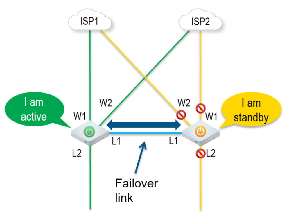
This section describes HA Option 1: Standard HA.
Topology Overview for HA Option 1
The following figure shows a conceptual overview of HA Option 1.

The Edges, one Active and one Standby, are connected by L1 ports to establish a failover link. The Standby VeloCloud Edge blocks all ports except the L1 port for the failover link.
Prerequisites for HA option 1
- The LAN side switches in the following configuration descriptions must be STP capable and configured with STP.
- In addition, VeloCloud Edge LAN and WAN ports must be connected to different L2 switches. If it is necessary to connect the ports to the same switch, then the LAN and WAN ports must be isolated.
- The two VCEs must have mirrored physical WAN and LAN connections.
Deployment Types for HA option 1
- Deployment Type One uses L2 switches
- Deployment Type 2 uses a combination of L2 and L3 switches
Deployment Type One: High Availability (HA) using L2 Switches
The following figure shows the network connections using only L2 switches.

W1 and W2 are WAN connections used to connect to the L2 switch to provide WAN connectivity to both ISPs. The L1 link connects the two VCEs and is used for ‘keep-alive’ and communication between the VCEs for HA support. The VCE’s LAN connections are used to connect to the access layer L2 switches.
Considerations for Deployment Type One
- The same ISP link must be connected to the same port on both Edges.
- Use the L2 switch to make the same ISP link available to both Edges.
- The Standby VCE does not interfere with any traffic by blocking all its ports except the failover link (L1 port).
- Session information is synchronized between the Active and Standby VeloCloud Edges through the failover link.
- If the Active Edge detects a loss of a LAN link, it will also failover to the Standby if it has an Active LAN link.
Deployment Type Two: HA Availability (HA) using L2/L3 Switches
The following figure shows the network connections using L2 and L3 switches.

The VeloCloud Edge WAN connections (W1 and W2) are used to connect to L2 switches to provide a WAN connection to ISP1 and ISP2 respectively. The L1 connections on the VeloCloud Edges are connected to provide a failover link for HA support. The VeloCloud Edge LAN connections are used to connect L2 Switches, which have several end-user devices connected.
Considerations for Deployment Type Two
- HSRP/VRRP is required on the L3 switch pair.
- The VeloCloud Edge's static route points to the L3 switches’ HSRP VIP as the next hop to reach the end stations behind L2 switches.
- The same ISP link must be connected to the same port on both VeloCloud Edges. The L2 switch must make the same ISP link available to both Edges.
- The Standby VeloCloud Edge does not interfere with any traffic by blocking all of its ports except the failover link (L1 port).
- The session information is synchronized between the Active and Standby VeloCloud Edges through the failover link.
- The HA pair also does a failover from Active to Standby on detecting the L1 loss of LAN / WAN links.
- If Active and Standby have the same number of LAN links which are up, but Standby has more WAN links up, then a switchover to Standby will occur.
- If the Standby Edge has more LAN links up and has at least one WAN link up, then a failover to the Standby will occur. In this situation, it is assumed that the Standby Edge has more users on the LAN side than the Active Edge, and that the Standby will allow more LAN side users to connect to the WAN, given that there is some WAN connectivity available.