


The VMware SD-WAN by VeloCloud solution supports the following third-party firewalls, Palo Alto Networks VM-series, Fortinet FortiGate VNF, and Check Point CloudGuard Edge VNF. See the sections below to successfully deploy and forward traffic through VNF on the VMware SD-WAN Edge.
Before you begin:
- You must have an activated SD-WAN Edge 520V or 840.
- You must have a SD-WAN Orchestrator version 3.3.2 or later.
- You must be running an SD-WAN Edge software version 3.3.2 or later.
- You must have VNF Manager add on license.
About this task:
The procedures in this section provide steps on how to configure a VNF instance via the SD-WAN orchestrator. This task requires additional steps from outside of the orchestrator from the third-party firewall you’ve chosen. Please refer to the appropriate deployment guides for these additional steps
Procedure to Configure a VNF Instance:
Step 1: Enable Edge NFV and Edge VNF
- If you have the necessary Operator access, go to Configure > Customer in the navigation panel of the VCO.
The Customer Configuration screen appears.
- In the Edge NFV area, check the Enable Edge NFV checkbox (image below).
- In the Security VNFs area, enable the applicable security VNFs: Enable Check Point Networks Firewall, Enable Fortinet Networks Firewall, or Enable Palo Alto Networks Firewall.
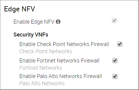
After you enable Edge NFV and choose a Security VNF, the Enable Edge NFV checkbox becomes disabled because there is now a network service associated with it.
- Click the Save Changes button.
Step 2: Define a VNF Instance
- From the VeloCloud Orchestrator, go to Configure > Network Services.
The Services screen appears.
- In the VNFs area, click the New button.
The VNF Service Management Configuration dialog box appears.
- In the VNF Service Management Configuration dialog box complete the following:
- Type in a name in the appropriate text box for the VNF service instance.
- From the VNF Type drop-down menu, choose one of the following for the VNF Type: Check Point Firewall, Fortinet Firewall, or Palo Alto Networks Firewall.
Note: The VNF Service Management Configuration dialog box will require different information depending upon which VNF type you choose. If you chose Palo Alto Networks Firewall, see Step 3c. If you chose Check Point Firewall, see step 3d. If you chose Fortinet Firewall, see step 3e. Follow the appropriate steps below to determine what types of information is required in the VNF Management Configuration dialog box.
- If you’ve chosen Palo Alto Networks Firewall as the VNF type, enter in the following in the VNF Management Configuration dialog box as described in the steps below:

- Type in a Primary Panorama IP Address and a Secondary Panorama IP Address, if necessary.
- Type in the Panorama Auth Key in the appropriate text box. The customer must configure the Auth Key password on Panorama. VNF uses the Auth Key to login and communicate with Panorama.
- Click Save Changes.
The VNFs area updates, displaying the newly created VNF configuration.
- Define VNF Licenses for Palo Alto Networks. (These licenses will be applied to one or more VNF configured Edges).
- In the VNF Licenses area, click the New button (from theConfigure > Network Services screen).
- In the VNF License Configuration dialog box complete the folllowing steps below:
- Type in a name in the appropriate textbox.
- In the VNF Type drop-down menu, choose the only available option, Palo Alto Networks Firewall.
- Type in the License Server API Key in the appropriate textbox. The customer gets this key from their Palo Alto Networks account. The VCO uses this key to communicate with Palo Alto Networks license server.
- Type in the Authorization Code in the Auth Code textbox. The customer must purchase the Auth Code from Palo Alto Networks). See image below.
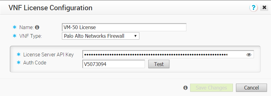
- Click the Test button to validate the configuration.
- If your configuration is valid, a confirmation indicator will display next to the Test button.
- If the configuration is not valid, an invalid message icon will display next to the Test button.
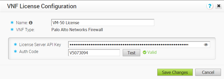
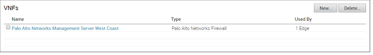
- Click Save Changes. The customer can now apply one or more of these licenses to VNF configured Edges.
The VNF Licenses area updates as shown in the image below.

- Proceed to Step 3: Configure Edge-specfic Settings on the VNF.
- If you’ve chosen Check Point Firewall as the VNF type, enter the following in the VNF Service Management Configuration dialog box as described below. (See image below).
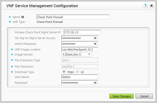
- Type in a name in the appropriate text box for your VNF service instance.
- From the VNF Type drop-down menu, choose Check Point Firewall.
- Type in the Primary Check Point Mgmt Server IP in the appropriate text box. This is the Check Point Smart Console IP address that the Check Point CloudGuard Edge will connect to.
- Type in the SIC Key for Mgmt Server Access in the appropriate text box. This is the password used to register the VNF to the Check Point Smart Console.
- Type in the VNF Image Location in the appropriate text box. This is the image location where the SD-WAN Orchestrator will download the VNF image.
- From the Image Version drop-down menu, select a version of the Check Point VNF image.
- File Checksum Type autopopulated field – Specifies the method used to validate the VNF image. This field is automatically populated after you choose an image version from the above step.
- File Checksum autopopulated field – Specifies the checksum used to validate the VNF image. This field is automatically populated after you choose an image version from the previous step.
- Download Type radio buttons – Specify where the image is available by choosing one of the following options, s3 or https. NOTE: When you select https, enter the username and password in the appropriate text field. When you select s3, enter the AccessKeyid and SecretAccessKey in the appropriate text field.
- Click the Save Changes button.
The VNFs area updates displaying the newly created VNF configuration (see image below)
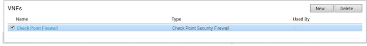
- Proceed to Step 3: Configure Edge-specific Settings on the VNF.
- If you’ve chosen Fortinet Firewall as the VNF type, follow the steps below in the VNF Service Management Configuration dialog box (see image below).

- Type in a name in the appropriate text box for your VNF service instance.
- Choose the VNF type Fortinet Firewall from the drop-down menu.
- Type in the Fortinet Mgmt Server IP in the appropriate text box. This is the IP address of the FortiManager for the FortiGate to connect to.
- Type in the Registration Password. This is the password used to register the VNF to the FortiManager.
- Type in the VNF Image Location. This is the image location for the SD- WAN Orchestrator to download the VNF image.
- From the Image Version drop-down menu, select a version of the Fortinet VNF image.
- File Checksum Type text box– Specifies the method used to validate the VNF image. This field is automatically populated after you choose an image version from the previous step.
- File Checksum text box – Specifies the checksum used to validate the VNF image. This field is automatically populated after you choose an image version from the previous step.
- Download Type radio buttons – Specify where the image is available by choosing one of the following options, s3 or https. NOTE: When you select https, enter the username and password in the appropriate text field. When you select s3, enter the AccessKeyid and SecretAccessKey in the appropriate text field.
- Click the Save Changes button.
The VNFs area updates displaying the newly created VNF configuration (see image below).
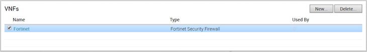
- Proceed to Step 3: Configure Edge-specific Settings on the VNF.
Step 3: Configure Edge-specific Settings on the VNF
- From the VCO navigation panel, go to Configure > Edges > Devices tab.
- Choose an Edge on the Edges screen.
- Click the Device tab.
- In the Device tab screen, scroll down to the Security VNF area, click the Edit button.
The Edge VNF Configuration dialog box displays.
- In the Edge VNF Configuration dialog, check the Deploy checkbox (image below).
- In the Edge VNF Configuration dialog box, check the Deploy checkbox.

- In the VM Configuration area of the Edge VNF Configuration dialog box complete the following:
- Choose a VLAN from the drop-down menu. (This VLAN will be used for the VNF management).
- Type in the Management IP. Note that when the VNF is created, it will automatically specify the IP address of the VLAN interface as a default Gateway.
- Type in the Hostname in the appropriate text box.
- Choose a Deployment State. The type of deployment state will be determined based on what type of predefined “Security VNF” network service as described below.
- If you choose Fortinet or Checkpoint as a security VNF, choose from one of the following two Deployment States: Image Downloaded and Powered On or Image Downloaded and Powered Off. (See the table below for a description of these states).
- If you choose PaloAlto Networks as a security VNF, choose from one of the following two Deployment States: Powered On or Powered Off. (See the table below for more information about these states).
State Definition Powered On After builing the firewall VNF on the Edge, power it up. Powered Off After building the firewall VNF on the Edge, keep it powered down. Note: Traffic only transits the VNF when it is in the “Powered On” state, which requires that at least one VLAN or routed interface be configured for VNF insertion. Do not select ‘Powered Off’ if you intend to send traffic through the VNF.
- In the Security VNF drop-down menu, choose one of the following: a predefined VNF network service or a new network service (if you choose the later option, the Network Service VNF Configuration dialog box opens so you can create a new VNF service).
- If you choose Palo Alto as your Security VNF:
- Choose a license from the License drop-down menu.
- Type in the Device Group Name and the Config Template Name in the appropriate textboxes. (The Device Group Name and the Config Template Name are pre-configured on the Panorama server).
- Click the Update button.
The Security VNF panel updates.

- If you choose Fortinet as your Security VNF:
- Choose an Inspection mode. (Proxy mode is selected by default).
- Drag the license file into the License box located at the bottom of the screen.
Click the Update button.
The Security VNF panel updates.
- If you choose Check Point as your Security VNF:
- Choose Check Point from the Security VNF drop-down menu.
- Click the Update button.
The Security VNF panel updates.
- If you choose Palo Alto as your Security VNF:
Step 4: Insert VNF into the Dataplane
The VNF can be inserted to both the VLAN as well as routed interface. If you choose to use routed interface, make sure the trusted source is checked and disabled WAN overlay on that interface.
- If you are not in the Device tab screen for a VeloCloud Edge, go to Configure > Edges in the navigation panel of the VCO.
The VeloCloud Edges screen appears.
- Select an Edge and click the Device icon associated with the selected Edge located the Device column.
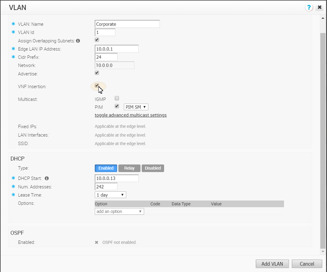
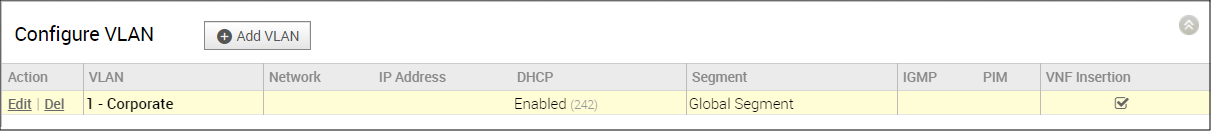
- Scroll down to the Configure VLAN area.
- Click the applicable VLAN Edit link.
- In the VLAN dialog box, click the VPN Insertion checkbox to insert the VNF into VLAN. This step redirects traffic from a specific VLAN into the VNF.
- Insert the VNF into Layer 3 interfaces or sub-interfaces. This step redirects traffic from specific Layer 3 interfaces or subinterfaces into the VNF.
(Optional) Step 5: Define Mapping between Segments and Service VLANs
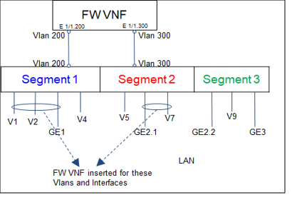
This step is applicable if multiple traffic segments must be redirected to the VNF.
As shown in the following figure, the segment in which the VNF is inserted is assigned a unique VLAN ID. The FW policy on the VNF is defined using these VLAN IDs. Traffic from VLANs and interfaces within these segments is tagged with the VLAN ID allocated for that particular segment.
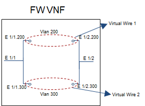
The following figure zooms into the FW VNF area of the preceding figure.
Note the following about Firewall VNF (The image below pertains to Palo Alto Networks only):
- One Virtual Wire per Vlan ID
- Sub-interface pairs should be created on Panorama per Virtual Wire
- FW policies are associated with the Virtual Wire
- Overlapping addresses can be used in separate Virtual Wires
To define mapping between segments and service VLANs (Step 3), complete the following substeps:
- Go to Configure > Segments.
- For available segments, type in Service VLANs for each segment.
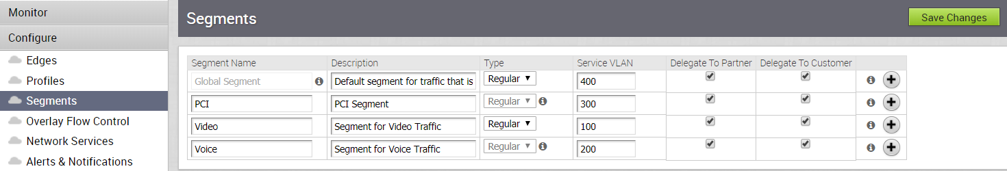
- Click Save Changes.
