


LAN-Side NAT Rules allow you to NAT IP addresses in an unadvertised subnet to IP addresses in an advertised subnet. For both the Profile and Edge levels, within the Device Settings configuration, LAN-side NAT Rules has been introduced for the 3.3.2 release and as an extension, LAN side NAT based on source and destination, same packet source and destination NAT support have been introduced for the 3.4 release.
From the 3.3.2 release, VMware introduced a new LAN-side NAT module to NAT VPN routes on the Edge. The primary use cases are as follows:
- Branch overlapping IP due to M&A
- Hiding the private IP of a branch or data center for security reasons
- Source or Destination NAT for all matched subnets, both 1:1 and Many:1 are supported (3.3.2 release)
- Source NAT based on Destination subnet or Destination NAT based on Source subnet, both 1:1 and Many:1 are supported (3.4 release)
- Source NAT and Destination 1:1 NAT on the same packet (3.4 release)
- LAN-side NAT supports traffic over VCMP tunnel. It does not support underlay traffic.
- Support for "Many:1" and "1:1" (e.g. /24 to /24) Source and Destination NAT.
- If multiple rules are configured, only the first matched rule is executed.
- LAN-side NAT is done before route or flow lookup. To match traffic in the business profile, users must use the NATed IP.
- By default, NATed IP are not advertised from the Edge. Therefore, make sure to add the Static Route for the NATed IP and advertise to the Overlay.
- Configurations in 3.3.2 will be carried over, no need to reconfigure upon 3.4 upgrade.
LAN-side NAT (3.3.2 Release)
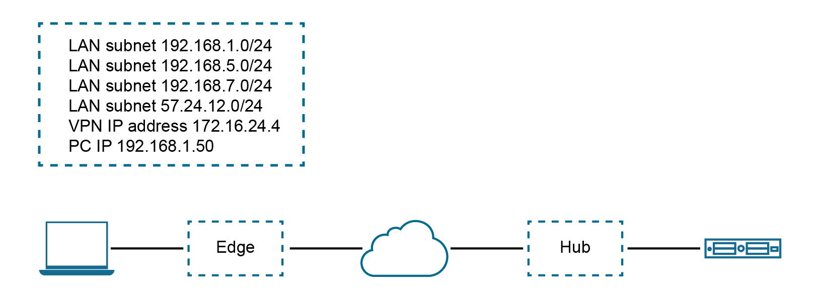
Use Case Number One: "Many:1 Source NAT"
In this scenario, a third-party has assigned multiple non-overlapping subnets to a customer's site. The server in the customer's data center recognizes traffic from this third-party by a single IP address at any given site.
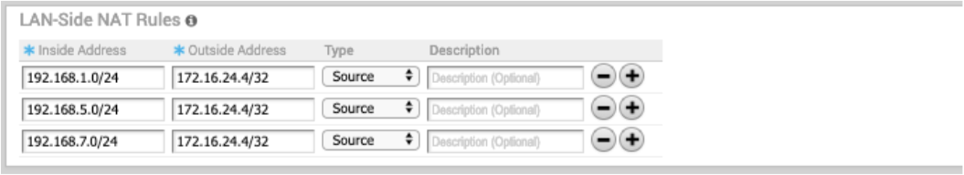
The configuration required for Use Case Number One for Version 3.3.2: New rule: LAN-side NAT 192.168.1.0/24 -> 172.16.24.4/32
As shown in the image below, because the NAT rule is a single IP, TCP and UDP traffic will be NAT'ed. Therefore, in this example, 192.168.1.50 becomes 172.16.24.4 with an ephemeral source port for TCP/UDP traffic, ICMP traffic becomes 172.16.24.4 with a custom ICMP ID for reverse lookup, and all other traffic will be dropped.
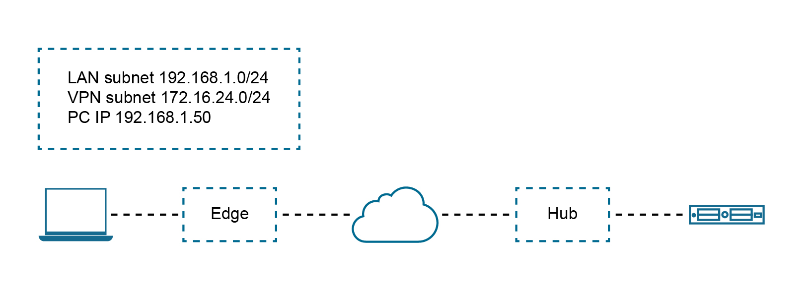
Use Case Number Two: "1:1 Source NAT"
In this scenario, the LAN subnet is 192.168.1.0/24. However, this is an overlapping subnet with other sites. A unique subnet of equal size, 172.16.24.0/24 has been assigned to use for VPN communication at this site. Traffic from the PC must be NAT'ed on the Edge prior to the route lookup, otherwise the source route will match 192.168.1.0/24 which is not advertised from this Edge and traffic will drop.
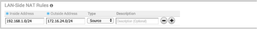
The configuration required for Use Case Number Two: New rule: LAN-side NAT 192.168.1.0/24 -> 172.16.24.0/24
Because the subnets match in size, all bits matching the subnet mask will be NAT'ed. Therefore, in the image below example, 192.168.1.50 becomes 172.16.24.50.
LAN-side NAT Based on Source or Destination (3.4 Release)
The 3.4 release introduces LAN-side NAT based on Source/Destination support as part of a single rule, in which you can enable NAT only for a subset of traffic based on Source or Destination subnets. See the following use cases for this enhancement below.
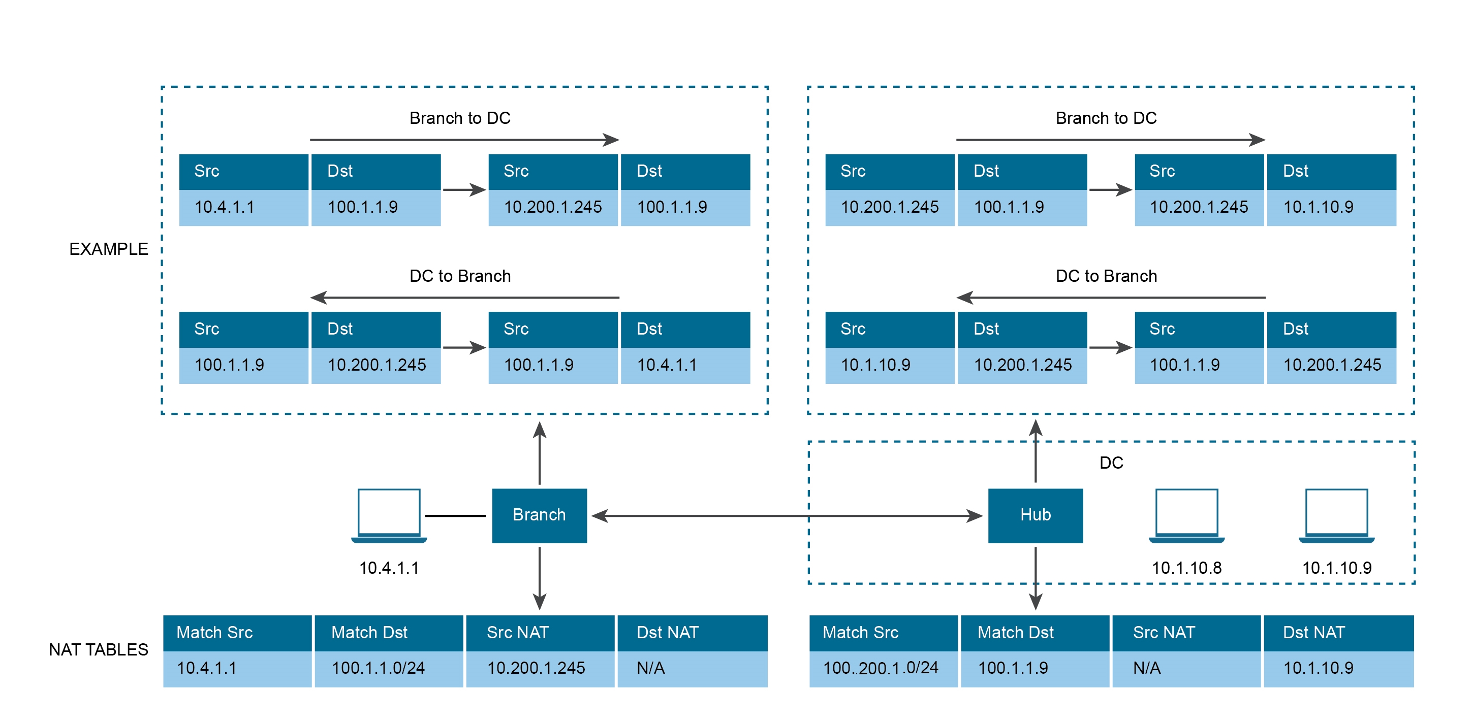
Use Case Number One: "Perform SNAT or DNAT with Source or Destination as Match Criteria"
In the illustration example below, the branch should NAT the source IP 10.4.1.1 to 10.200.1.245 only for the traffic destined to 100.1.1.0/24. Similarly, at the DC, the destination IP 100.1.1.9 should be NATed to 10.1.10.9 only if the traffic is received from source 10.200.1.0/24.
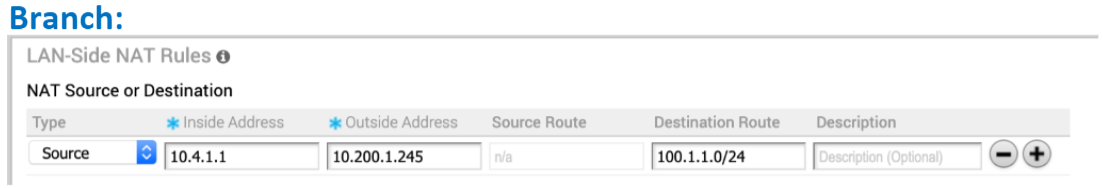
See the image below (LAN-side NAT Rules area for the Branch).
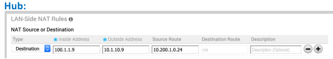
See the image below (LAN-side NAT Rules area for the Hub).
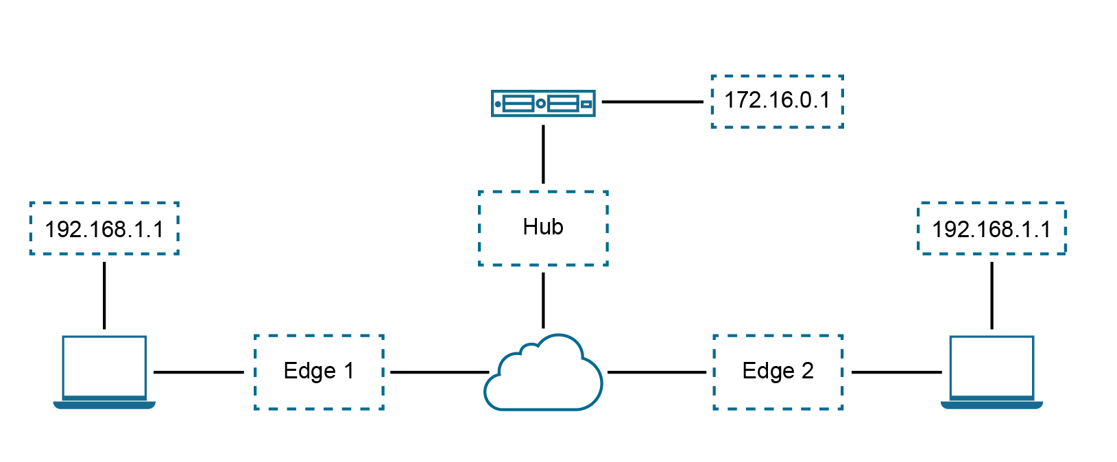
Use Case Number Two: To NAT Both Source and Destination IP on the Packet
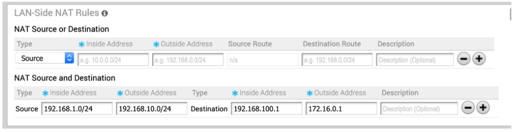
Consider the below scenario. In this example, each site in the network is assigned the same subnet so that the Branch LAN is identical at every site. "PC1" and "PC2" have the same IP address and both need to communicate with a server behind the Hub. We need to source NAT the traffic in order to use overlapping IP addresses, e.g. in Edge 1, PCs (192.168.1.0/24) should be NAT'ed to 192.168.10.0/24, in Edge2, PCs (192.168.1.0/24) should be NAT'ed to 192.168.20.0/24.
Also, for security reason, the server behind the Hub with real IP “172.16.0.1” should be presented to PCs as “192.168.100.1,” and this IP should not be distributed to SD-WAN between the Hub and Edge, source + destination combination rules on the same Edge are required.
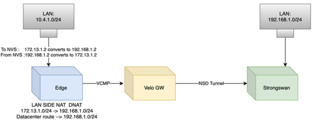
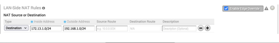
Use Case Number Three: Many-to-Many Destination NAT for a NSD Subnet
Configure Procedure
Note: If the users want to configure the default rule, “any” they must specify the IP address must be all zeros and the prefix must be zero as well: 0.0.0.0/0.
- From the navigational panel, go to Configure > Edges.
- In the Device Settings tab screen, scroll down to the LAN-Side NAT Rules area.
- In the LAN-Side NAT Rules area, complete the following for the NAT Source or Destination section: (See the table below for a description of the fields in the steps below).
- Enter an address for the Inside Address text box.
- Enter an address for the Outside Address text box.
- Enter the Source Route in the appropriate text box.
- Enter the Destination Route in the appropriate text box.
- Type a description for the rule in the Description textbox (optional).
- In the LAN-side NAT Rules area, complete the following for NAT Source and Destination: (See the table below for a description of the fields in the steps below).
- For the Source type, enter the Inside Address and the Outside Address in the appropriate text boxes.
- For the Destination type, enter the Inside Address and the Outside Address in the appropriate text boxes.
- Type a description for the rule in the Description textbox (optional).
| LAN-side NAT Rule | Type | Description |
|---|---|---|
| Type drop-down menu | Select either Source or Destination | Determine whether this NAT rule should be applied on the source or destination IP address of user traffic. |
| Inside Address text box | IPv4 address/prefix, Prefix must be 1-32 | The "inside" or "before NAT" IP address (if prefix is 32) or subnet (if prefix is less than 32). |
| Outside Address text box | IPv4 address/prefix, Prefix must be 1-32 | The "outside" or "after NAT" IP address (if prefix is 32) or subnet (if prefix is less than 32). |
| Source Route text box | - Optional - IPv4 address/prefix - Prefix must be 1-32 - Default: any |
For destination NAT, specify source IP/subnet as match criteria. Only valid if the type is “Destination.” |
| Destination Route text box | - Optional - IPv4 address/prefix - Prefix must be 1-32 - Default: any |
For source NAT, specify destination IP/subnet as match criteria. Only valid if the type is “Source.” |
| Description text box | Text | Custom text box to describe the NAT rule. |
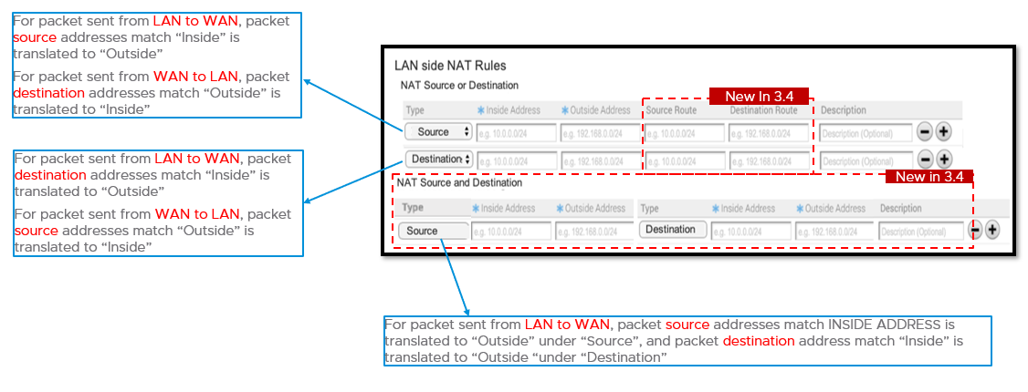
LAN-side NAT "Cheat Sheet"
- Traffic direction: LAN->WAN
- What needs to be translated: packet source address
- Config mapping:
- NAT Type = “Source”
- Orig IP = “Inside Address”
- NAT IP = “Outside Address”
| NAT Type | Inside | Outside | Type | LAN->WAN Behavior |
|---|---|---|---|---|
| Source | A.0/24 | B.0/24 | 1:1 | A.1 translates to B.1, A.2 to B.2, etc. |
| Source | A.0/24 | B.1/32 | Many:1 | A.1 and A.2 translate to B.1 |
| Source | A.1/32 | B.0/24 | 1:1 | A.1 translates to B.1, other B.X are unused |
- Traffic direction: WAN -> LAN
- What needs to be translated: packet destination address
- Config mapping:
- NAT Type = “Source”
- Orig IP = “Outside Address”
- NAT IP = “Inside Address”
| NAT Type | Inside | Outside | Type | WAN->LAN Behavior |
|---|---|---|---|---|
| Source | A.0/24 | B.0/24 | 1:1 | B.1 translates to A.1, B.2 to A.2, etc. |
| Source | A.0/24 | B.1/32 | Many:1 | B.1 translates to A.1 |
| Source | A.1/32 | B.0/24 | 1:Many | B.1 and B.2 translate to A.1 |
- Traffic direction: LAN->WAN
- What needs to be translated: packet destination address
- Config mapping:
- NAT Type = “Destination”
- Orig IP = “Inside Address”
- NAT IP = “Outside Address”
| NAT Type | Inside | Outside | Type | LAN->WAN Behavior |
|---|---|---|---|---|
| Destination | A.0/24 | B.0/24 | 1:1 | A.1 translates to B.1, A.1 to B.2, etc. |
| Destination | A.0/24 | B.1/32 | Many:1 | A.1 and A.2 translate to B.1 |
| Destination | A.1/32 | B.0/24 | 1:Many | A.1 translates to B.1 |
- Traffic direction: WAN->LAN
- What needs to be translated: packet source address
- Config mapping:
- NAT Type = “Destination”
- Orig IP = “Outside Address”
- NAT IP = “Inside Address”
NAT Type Inside Outside Type WAN->LAN Behavior Destination A.0/24 B.0/24 1:1 B.1 translates to A.1, B.2 to A.2, etc. Destination A.0/24 B.1/32 Many:1 B.1 translates to A.1 Destination A.1/32 B.0/24 1:Many B.1 and B.2 translate to A.1
