AWS has announced Tunnel-less Connect on Cloud WAN. This document describes AWS components and how to configure for AWS and VMware SD-WAN.
The new AWS CloudWAN CNE Connect using Tunnel-less BGP capability provides a simpler way to build a global SD-WAN network using AWS backbone as a middle-mile transport network. With this capability, VMware SD-WAN appliances can natively peer with AWS Cloud WAN using BGP (Border Gateway Protocol) without requiring tunneling protocols like IPSec or GRE. This simplifies the integration of customer’s SD-WAN into AWS cloud and allows them to leverage the high bandwidth AWS backbone for branch-to-branch connectivity across different geographic regions. This feature also supports in-built network segmentation, enabling customers to build a secure SD-WAN at a global scale.
VMware SD-WAN Virtual Edges (vEdges) are typically deployed in what AWS calls a “Transport” VPC. This Transport VPC may then peered with other VPCs, TGWs, or in this case, a CNE (Cloud Network Edge) in the Cloud WAN backbone to achieve connectivity with resources the customer has homed into AWS.
For Cloud WAN CNE Connect, the vEdges provisioned in the Transport VPC will use the LAN-facing (routed, non-WAN) interface to establish a native L3 (i.e. unencapsulated) BGP peering with the CNE.
AWS Components
- Cloud WAN Core Network
- Policy definition
- Core Network Edge (CNE)
- Transport VPC
- VPC Attachment
- Connect Attachment
This assumes that the customer already has other resources in other AWS VPCs that use VPC peering to CNEs in Core Network. If not, the Core Network and CNEs must be defined, and attachments must be created to the customer’s existing workload VPCs.
AWS Configuration
- Using the following VMware online documentation to create vEdges in an AWS VPC:
- Virtual Edge Deployment Guide
- VMware SD-WAN AWS CloudFormation Template - Green Field
- VMware SD-WAN AWS CloudFormation Template - Brown Field
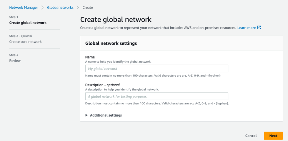
- On the AWS console, AWS Network Manager must be used to create a Global Network, if one does not already exist in the customer’s AWS deployment.
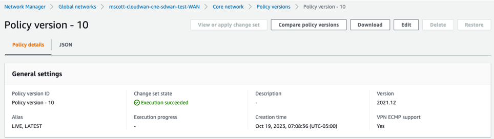
- Create a Policy version.
- A Policy version is where key details of the solution are defined and configured, as shown in the image below.
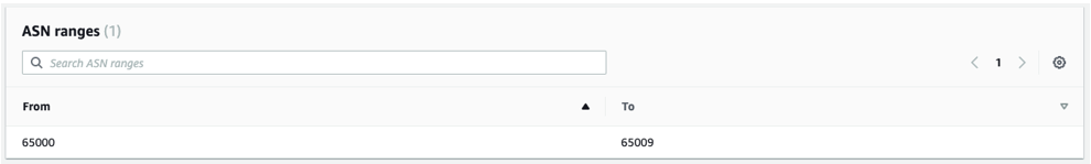
- Enter the BGP ASN ranges used by the CNEs.
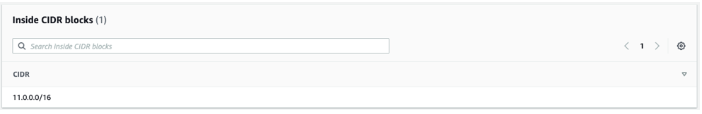
- In the global "Inside CIDR blocks," the CNEs will get their respective Inside CIDR blocks defined. Enter the CIDR in the appropriate text box, as shown in the image below.
- Search for Edge locations in the appropriate text box, as shown in the image below. The CNE locations define the specific AWS AZ where a CNE will be instantiated.
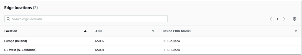 Note: The ASN and Inside CIDR Blocks for each Edge location are defined within the range defined above for the Global Network.
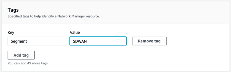
 - Search for Segments in the appropriate text box, as shown in the image below. Logical segments are defined using Tags. VPCs and Subnets may be tagged to define which segments they are a member of. In this example, the format is Key = “Segment”, Value = “SDWAN”, although the value is arbitrary.
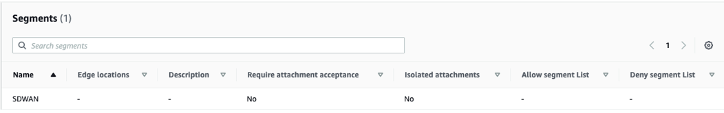 Note: Whatever value is used must match the value defined in the policy.
 - Attachment policies specify which Segments the VCP and Connect Attachments are a part of and what criteria are used. Search for the Attachment Policies in the appropriate text box, as shown in the image below. In the example below, a “tag-value” condition defines membership in the “SDWAN” segment defined above. The “Condition Values” are the key-value pair also defined above. This key-value pair must be present in VPCs and/or subnets for them to become Segment members.
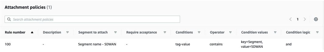 Note: This is arguably the least intuitive and most error-prone part of the entire configuration. If you aren’t seeing routes from your remote workload VPCs, check this. Other configurations and conditions are possible, but this is what worked in lab testing.
- A Policy version is where key details of the solution are defined and configured, as shown in the image below.
- CNE Attachments: There are two types of attachments used, VPC Attachment and Connect Attachment.
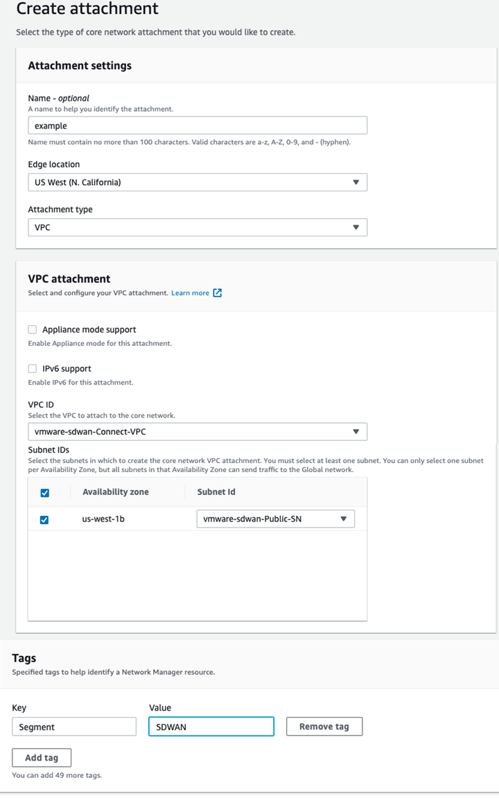
- VPC Attachments: Each SD-WAN Transport VPC will have a VPC attachment to its respective CNE. At least one subnet within the VPC must be specified when the VPC Attachment is created. In this example, The CNE in the us-west-1 AZ peers with the SD-WAN Transport VPC’s private LAN subnet. A key-value pair defining Segment membership is also necessary.
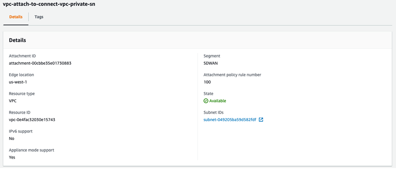
If the Policy has been configured correctly, the Attachment should show that it has been made part of the “SDWAN” Segment. The Attachment policy rule number being used will display, as shown in the image below.
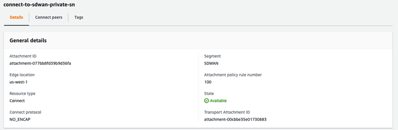
- Connect Attachments are where “Tunnel-less (No Encapsulation)” is configured. The Connect Attachment configuration must specify an existing VPC Attachment as the Transport Attachment ID, so the VPC Attachment must be configured first. As with the VPC Attachment, tags for Segment membership must be configured.
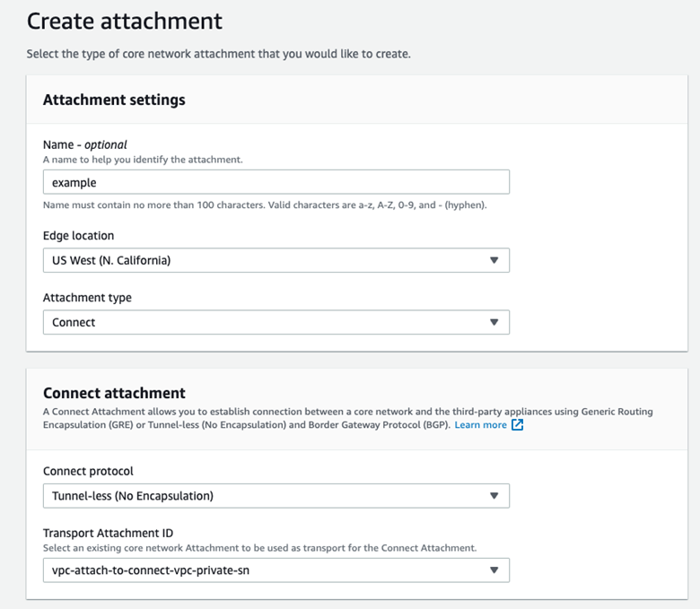
If the Policy has been configured correctly, the Attachment should show that it has been made part of the “SDWAN” Segment. Note that the Attachment policy rule number being used is shown, as is “NO_ENCAP” for the Connect protocol. See image below.
- VPC Attachments: Each SD-WAN Transport VPC will have a VPC attachment to its respective CNE. At least one subnet within the VPC must be specified when the VPC Attachment is created. In this example, The CNE in the us-west-1 AZ peers with the SD-WAN Transport VPC’s private LAN subnet. A key-value pair defining Segment membership is also necessary.
- Connect peers: Connect peers are created under the Connect Attachment. This is where the SD-WAN vEdge BGP peerings are defined in terms of the ASN and peer IP address. See image below.
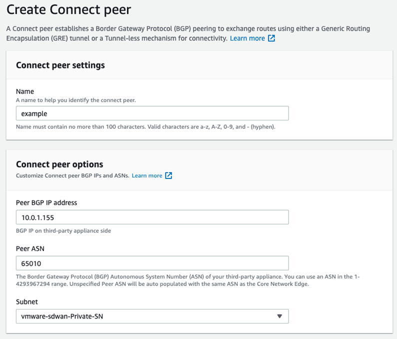
Once created, the AWS Console will provide two Core Network BGP peer IP addresses to use on the SD-WAN side of the BGP neighborship. These IPs will be selected randomly from the “Inside CIDR range” defined in the “Edge Locations” portion of the Policy above. See image below.
VMware SD-WAN Configuration
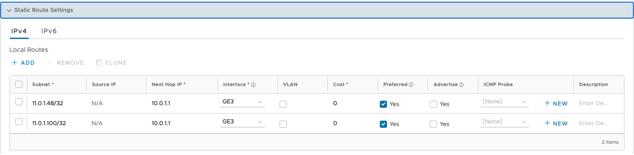
- Configure Static Route Settings, as shown in the image below.
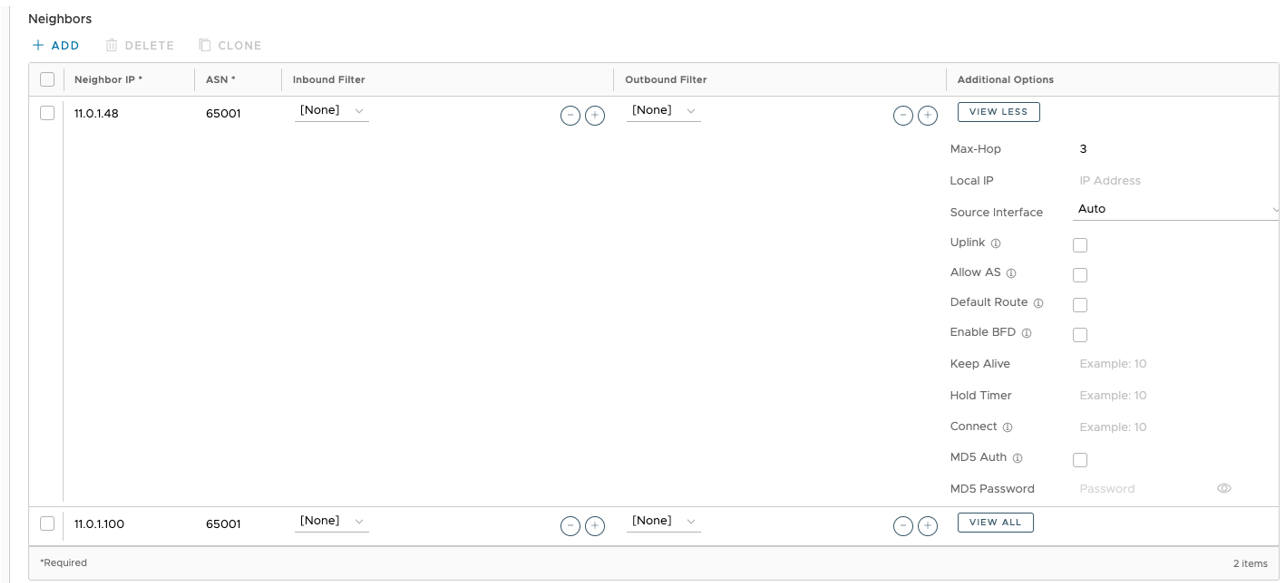
- When creating the BGP neighbors, set “Max-Hop” to 2 or more under Additional Options. See image below.
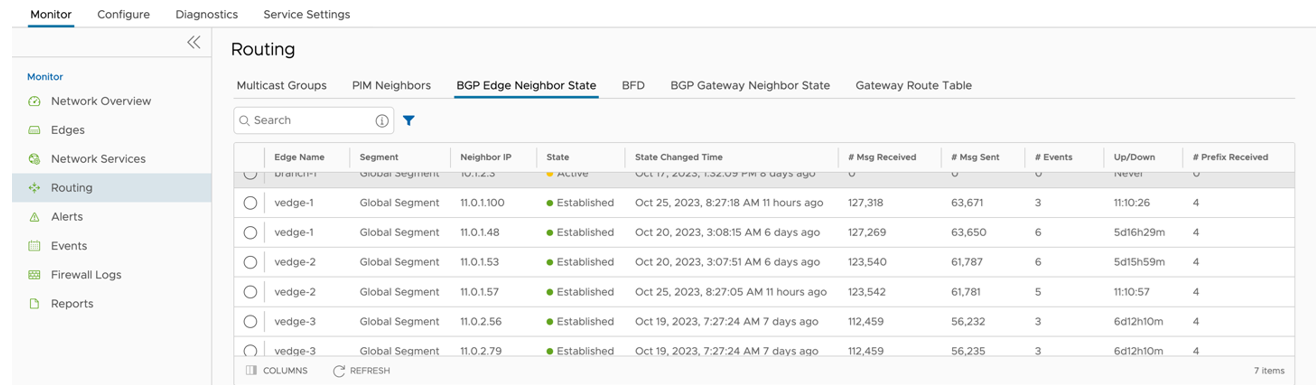
- Use Monitor > Routing > BGP Edge Neighbor State to verify that the BGP peer relationship has been Established with the Neighbor IPs configured. See image below for a visual of the Routing screen.