


This section explains how to deploy and operate an on-premises VMware VeloCloud SD-WAN solution, including the Orchestrator.
Overview
This section explains how to deploy and operate an on-premises VMware VeloCloud SD-WAN solution, which includes the VeloCloud Orchestrator, the VeloCloud Controller, and a co-located Edge Hub Cluster. It includes a reference architecture and the requirements and caveats for an on-premises SD-WAN deployment. It also covers the optional use of an External Certificate Authority and FIPS mode.
Reference Architecture
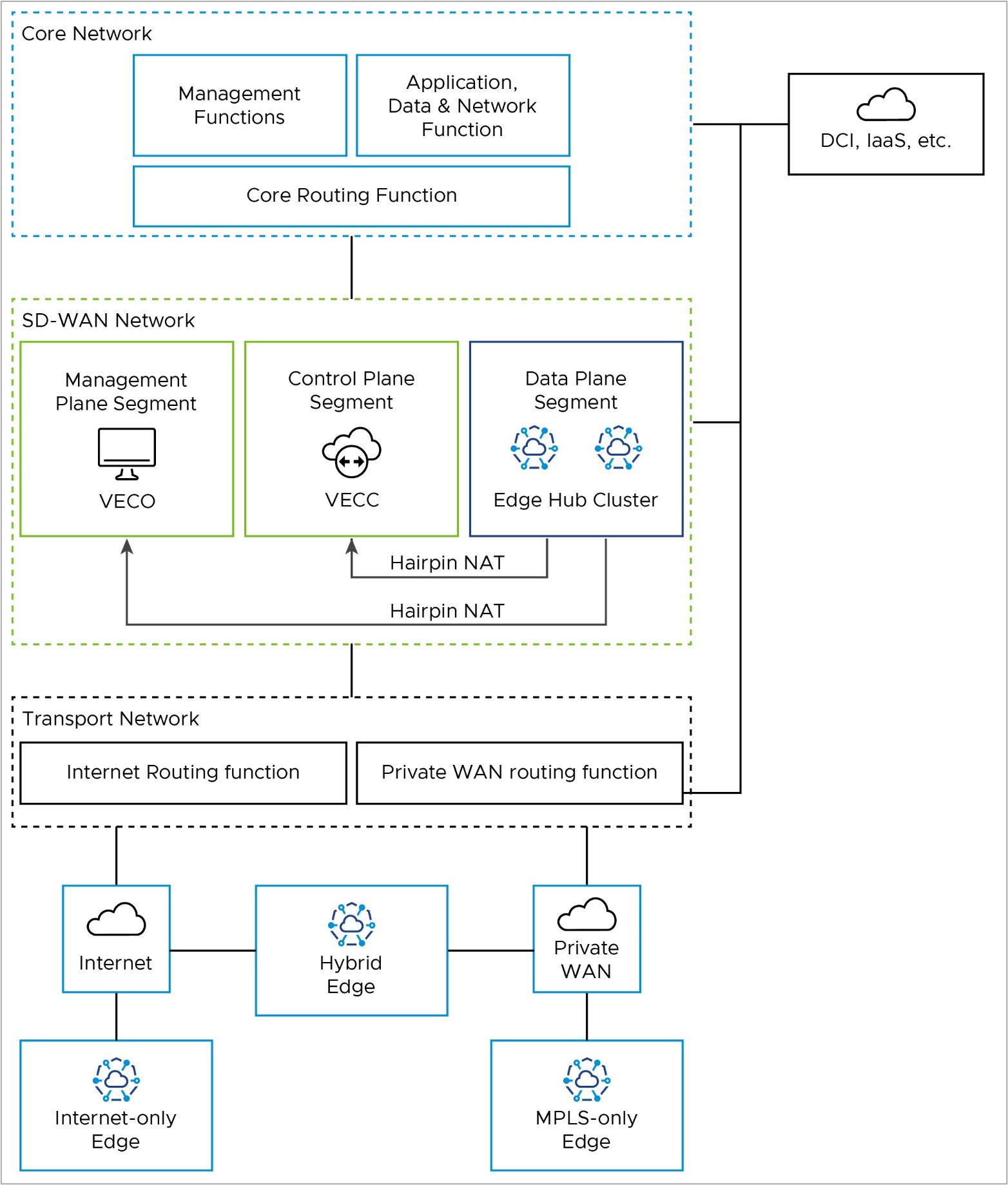
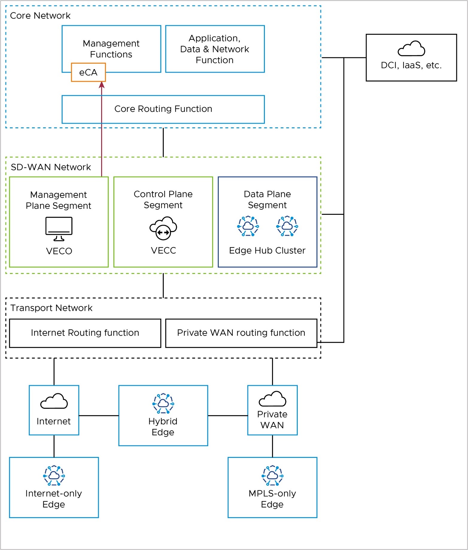
The reference architecture shows the logical grouping of the different VeloCloud SD-WAN and network functions. It also shows how the different nodes connect and communicate with each other. We expect that most real-world deployments would adapt the reference architecture in some way to accomodate their existing customer network.
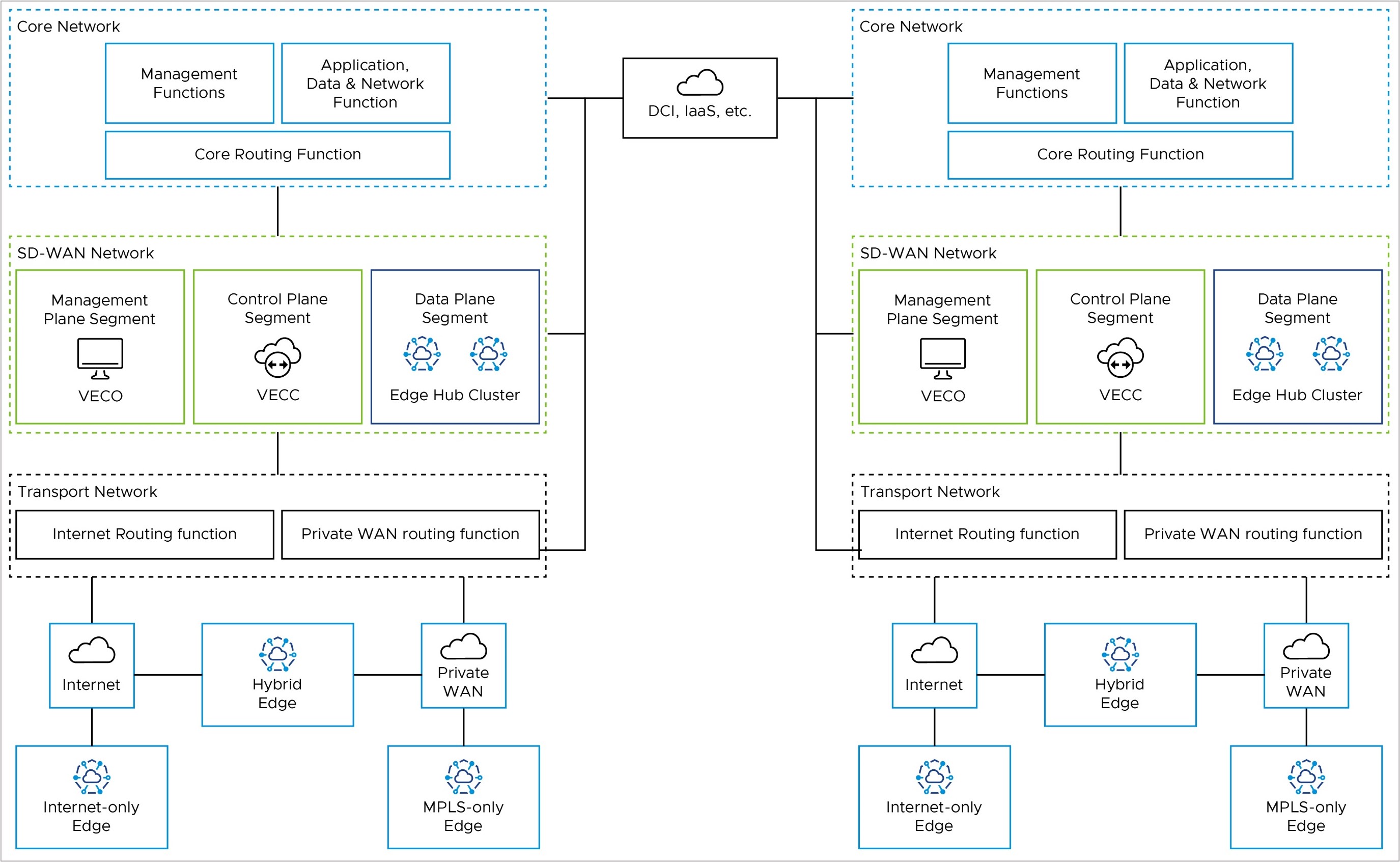
Core Network
The Core Network has applications and resources that users need to access to achieve their business goals. It may also have management functions, such as network monitoring and operations. If you use an External Certificate Authority (ECA), it may reside here. Data Center Interconnect (DCI, if you have it) also ends here from a routing perspective. You may separate these functions into different logical network segments.
SD-WAN Network
The SD-WAN Network is between the Transport Network and the Core Network. It has the Orchestrator (management plane), the Controller (control & routing plane), and the on-premises Hub Cluster (data plane), if you have one. These are all in the SD-WAN Network, but you may separate the Hub Cluster from the Orchestrator and Controller logically. This way, you can keep the SD-WAN management and control-plane traffic away from the branch data-plane traffic that uses the Hub Cluster to reach the core network resources.
Transport Network
The Transport Network has the WAN transport functions in the network, such as Public WAN (internet) and Private WAN (MPLS).
The Transport Network also has the Wide Area Network routing functions. This is where you would find Public WAN (internet) routers and Private WAN (MPLS CE) routers in an on-prem customer network. You may do NAT between public and private IP addresses here, or on an Edge firewall, depending on your network setup. You can also use wireless WAN (5G, for example) in the Public WAN case.
Firewalls
While not explicitly shown in the reference architecture, firewalls may be present. They may be deployed between the different functional blocks to provide security and traffic inspection or may be used to create different segments or zones within a functional block.
Packet Flows
This section illustrates the packet flow path in the reference architecture for various operations.
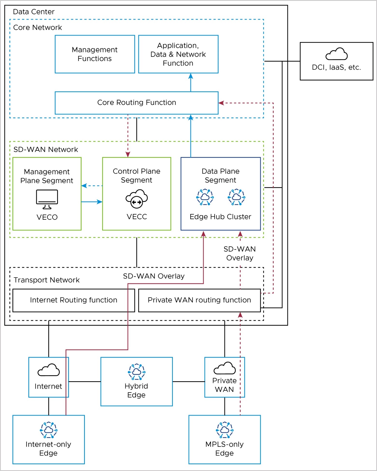
Edge Activation
An internet-only branch location activates via a public WAN through the Internet Routing Function in the Transport Network to the public IP address of the Orchestrator (solid red line).
An MPLS-only branch location activates to the Orchestrator through the Private WAN Routing Function in the Transport Network, then through the Core Routing function in the Core Network, to the Orchestrator’s private IP address (dashed red line).
A hybrid Edge location may use either.
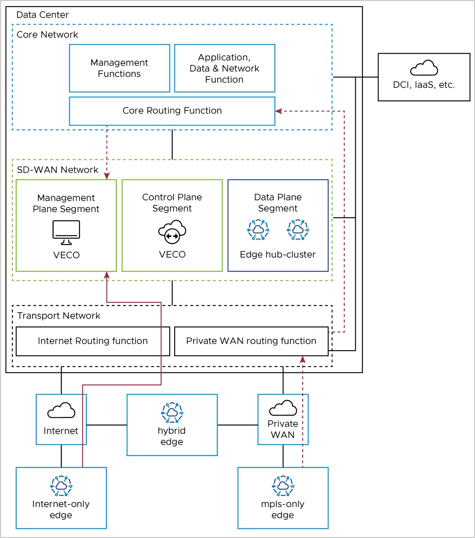
Management Plane: Edge to Orchestrator (VECO)
After activation, Edges use their Loopback IP addresses to connect to the Orchestrator. The Edge puts this connection inside the tunnel to the Controller, using any transport tunnel available. This connection then goes out of the Controller through its eth1 connection to the core network and reaches the Orchestrator. The Controller keeps the Loopback IP address as the source (no SNAT as with 1-arm Controller). The Orchestrator then replies to the Edge with its loopback address, which is dynamically routable via the Controller eth1 interface for symmetric routing.
Activated Edges may also communicate directly with the Orchestrator via the underlay, in which case they would use the same packet flow paths as in the Activation section.
If Edges use the SD-WAN overlay via the Controller (also called the VECC), the path depends on the Edge type. Internet-only Edges use the SD-WAN overlay via Public WAN to the public IP of the Controller (solid red line in the diagram), where they leave the tunnel, and go from the Controller's public IP address to the public IP address of the Orchestrator (solid blue line in the diagram).
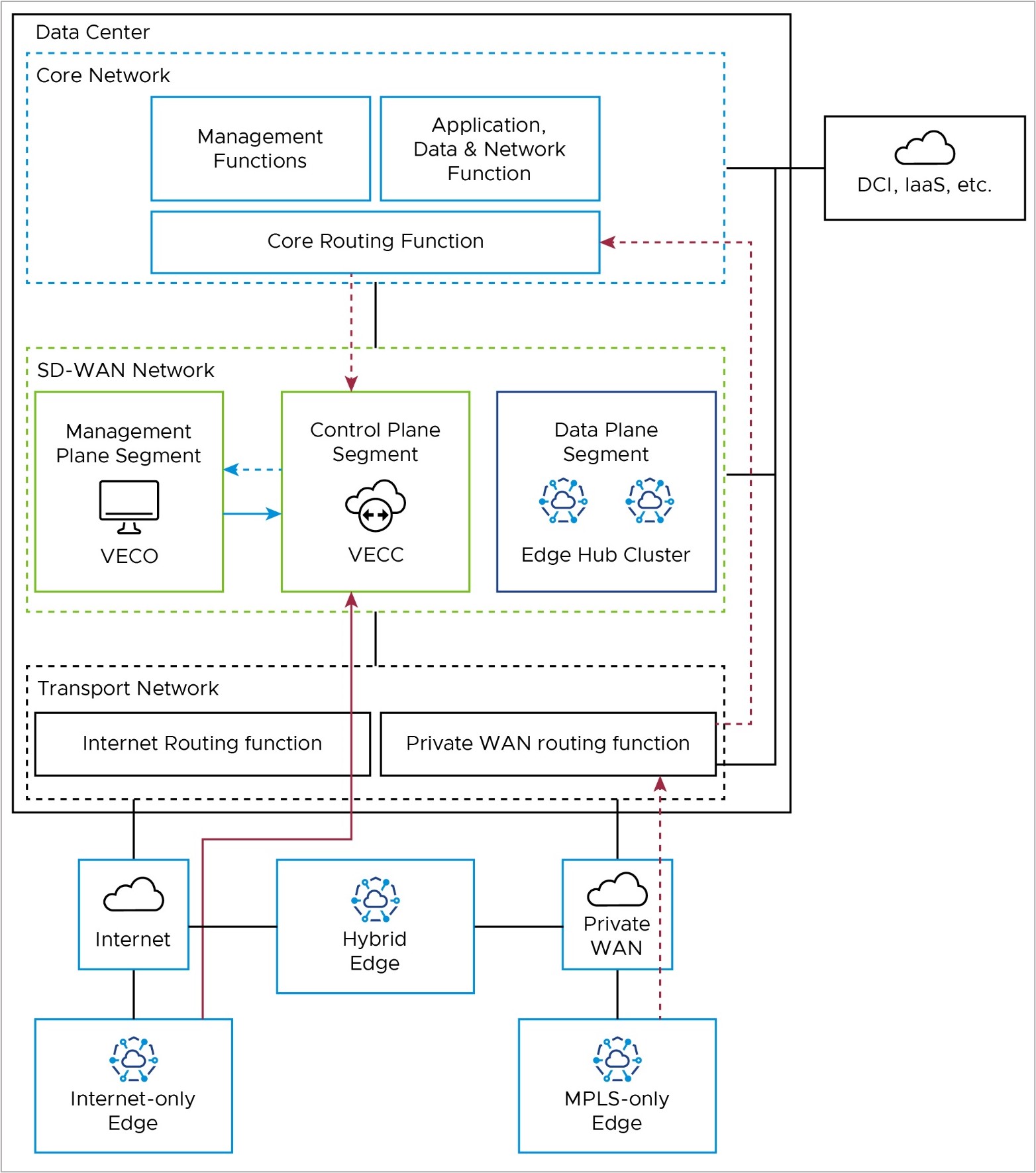
Control Plane: Edge to Controller (VECC)
All Edges connect to the Controller (also referred to as the VeloCloud Edge Cloud Controller, or VECC) with SD-WAN overlay tunnels. Usually, Edges have a Primary and Secondary Controller for backup. But for simplicity, we only show one Controller in the diagram.
Internet-only Edges connect to the Controller's public IP address with an SD-WAN overlay tunnel over the public internet. They use the Internet routing function in the Transport Network (solid red line in the diagram). MPLS-only Edges also connect to the Controller with an SD-WAN overlay tunnel, but they use the Controller's private IP address. They use the Private WAN routing function in the Transport Network and the Core Routing function in the Core Network (solid red line in the diagram).
Hub Cluster to Controller (VECC)/Orchestrator (VECO): Special Case
The on-premises Hub Cluster provides a data path from Edge locations to the Core network, where the applications and resources are hosted. Usually, the Hub connects to a data center and accesses the Orchestrator and Controller remotely. So, the Hub Cluster needs to use public IP addresses to communicate with the Orchestrator/Controller; it cannot use the LAN-side / private IP network. To make the Hub Cluster look like it is at a remote location and access the Orchestrator/Controller over the public internet, you may need to put the Hub Cluster in a separate network segment (for example, VRF). You may also need hairpin NAT functionality on a network device on the WAN side of the Hub Cluster, Controller, and Orchestrator.
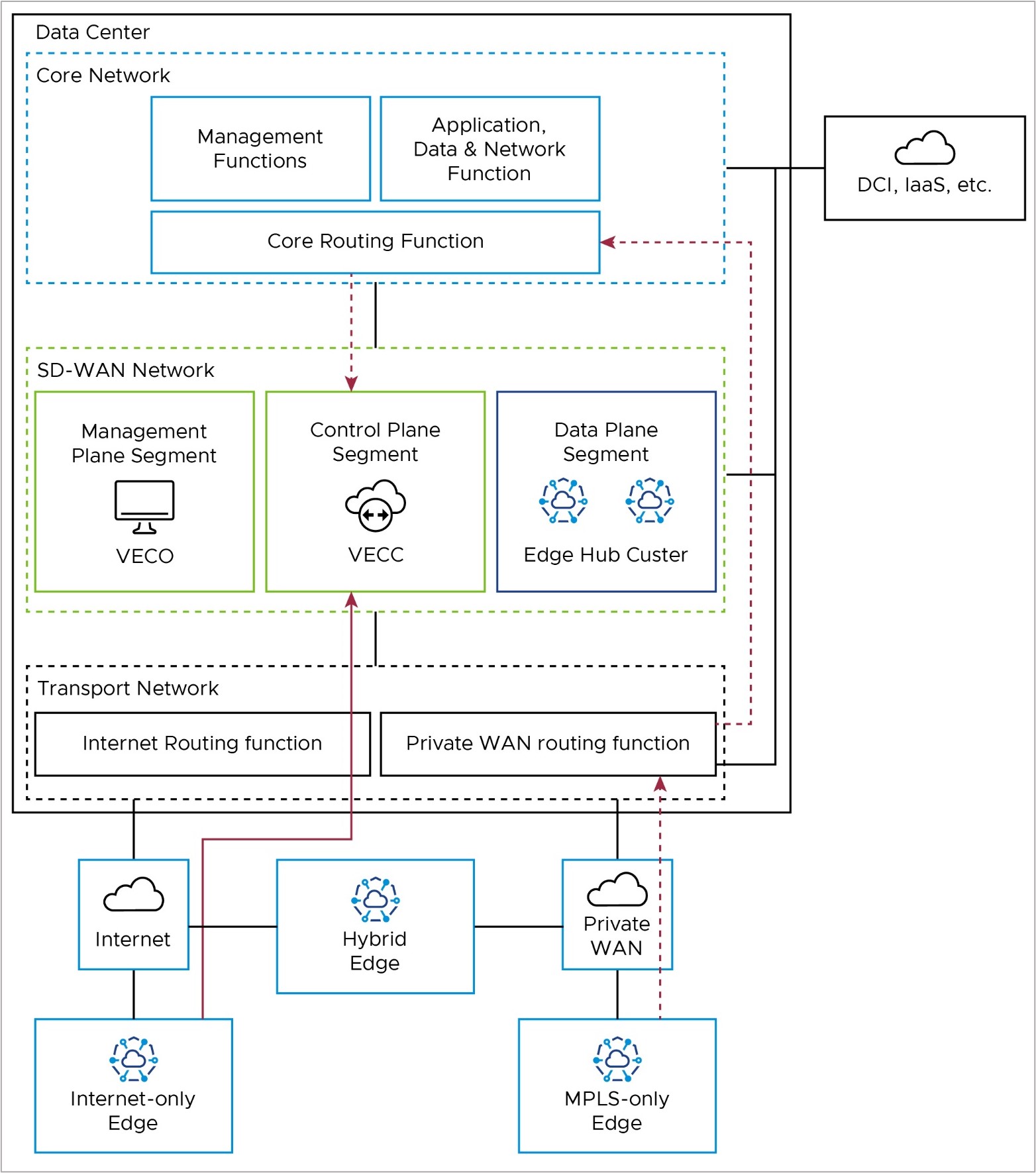
Edge to Core Network Functions – Data Path
Branch Edges access applications and resources in the datacenter via the on-premises Edge Hub Cluster. Internet-only Edges establish an SD-WAN overlay tunnel to the public WAN IP address of the Hub Cluster via the Internet routing function in the Transport Network (solid red line). Similarly, MPLS-only Edges establish an SD-WAN overlay tunnel to the private WAN IP address of the Hub Cluster via the private routing function in the Transport Network (dashed red line).
Once the data path reaches the Hub Cluster, it is removed from the SD-WAN tunnel and natively routed to applications in the core network via the Core Routing Function (solid blue lines).
This path is shared by all Edge types. Hybrid locations may use a combination of public and private SD-WAN overlays to the Edge Hub Cluster.
Orchestrator Disaster Recovery and Synchronization
When two VMware Edge Cloud Orchestrators (VECOs, or Orchestrators) are deployed as an Active-Standby Disaster Recovery (DR) pair in geographically diverse data center locations, there is both a real-time synchronization function (for configurations, alarms, metrics, etc.) between the active and standby, as well as a keep-alive function (to detect the failure of the active Orchestrator). This data path uses the private IP address of the Orchestrator, and uses a Data Center Interconnect to reach the remote DC via Core Routing function (red line).
More details on Orchestrator Disaster Recovery may be found in the Configure Orchestrator Disaster Recovery section.
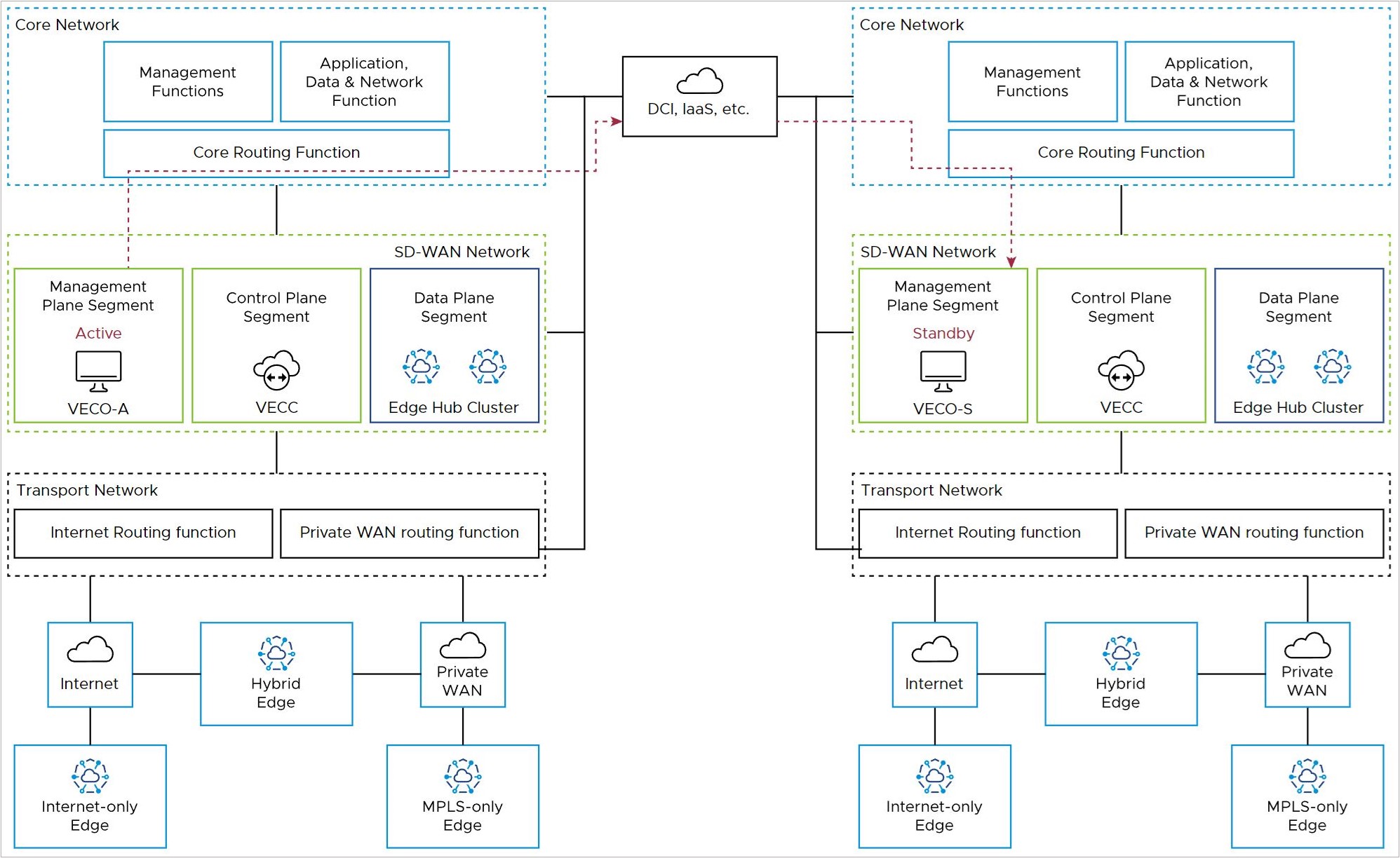
Controller to Orchestrator
The Orchestrator (management plane node) must communicate with the Controller (control plane node). In an on-premises deployment, this is done using the private IP addresses associated with the core network facing interfaces.
Depending upon the DR configuration and the location of the active Orchestrator (in the local or remote DC), this connectivity may take different paths.
For a co-located Orchestrator and Controller, the nodes may communicate directly within the SD-WAN Network block, or pass to the Core Routing Function (solid blue lines).
For a remote Orchestrator and Controller, the Controller must use the Core Routing function and DCI to reach the DR-active Orchestrator (dashed red lines).
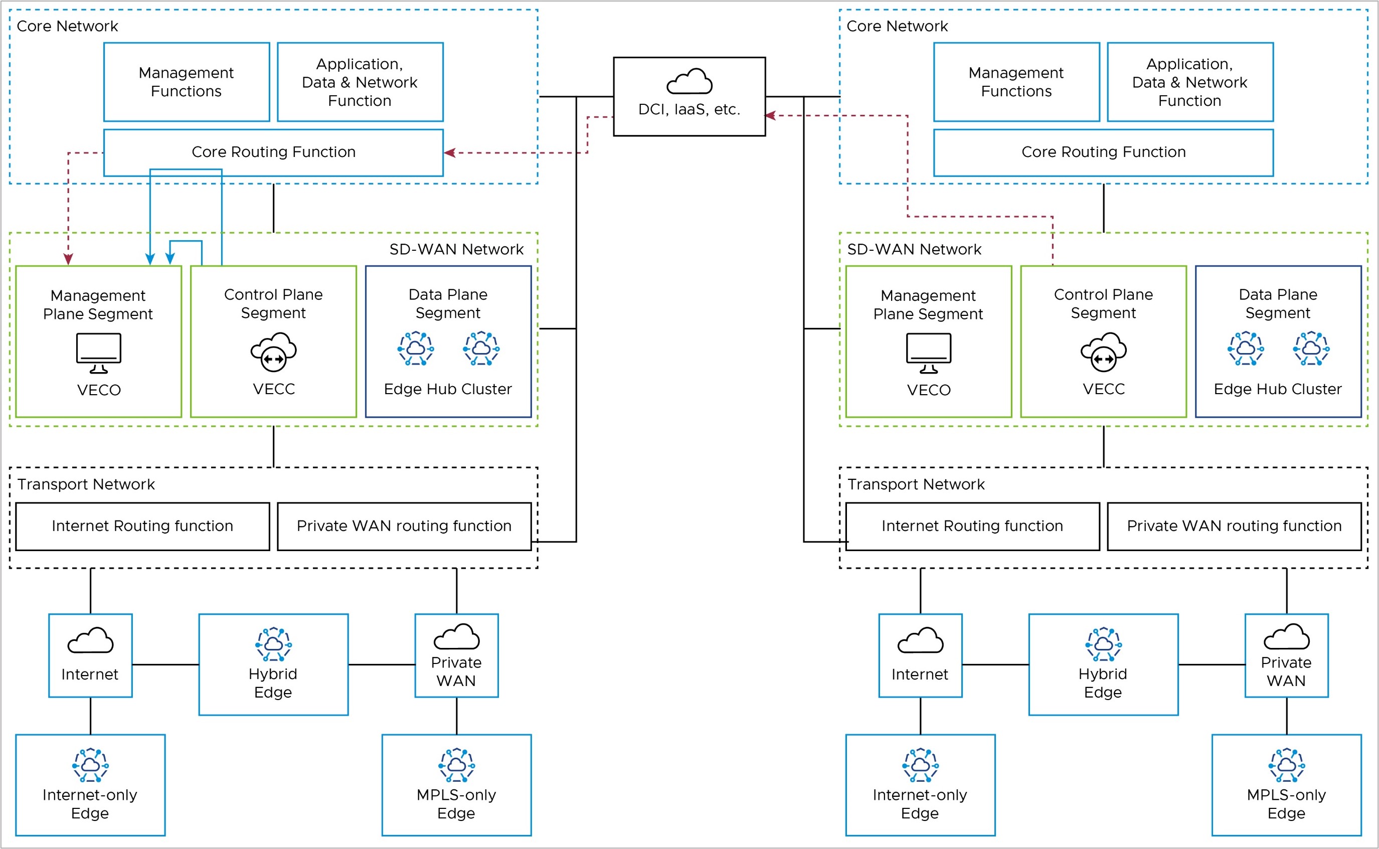
Controller to External Certificate Authority – Optional
IF an External CA (eCA) is used in the deployment, it would most likely reside in the Management Functions of the Core Network. The Orchestrator would use the private IP address of the core network facing interface to reach the eCA via the Core Routing Function.
If the Orchestrator is deployed as an active-standby DR pair, the Orchestrator fail-over may require the Orchestrator to reach the eCA via DCI.
More details on External CA may be found here:
Design Requirements & Assumptions for a Federal Deployment
This section includes requirements, caveats, unique aspects, and best practices specific to an on-premises Federal deployment.
- The solution spans two or more Data Centers.
- For redundancy, the VMware Edge Cloud Orchestrator (VECO, or just Orchestrator) is deployed in Disaster Recovery mode. This means that two Orchestrators are deployed in an active-standby pair, one in each Data Center.
- The paired Orchestrators must have L3 connectivity to one another (for example, via DCI) to maintain data synchronization in the event of a failure of the active Orchestrator.
- Controllers are also present in both data centers. Since either one of the VECOs in the DR pair may be active, there must be L3 reachability between the Controllers and VECOs at both data centers.
- Internet (public) transport only Sites: Branch Edge locations that have access to only Public WAN (internet) transport networks.
- Private transport only Sites: Branch Edge locations that have access to only Private WAN (MPLS) transport networks.
- Hybrid (public/private) transport mix Sites: Branch Edge locations that have access to both Public and Private WAN transport networks.
- In some networks, no reachability to public prefixes from private transport is allowed. For example, the Orchestrator and Controller are 1.1.1.1 and 2.2.2.2, there is no reachability to those addresses from the private transport. The private transports do not have a route to these addresses, nor can they be advertised, also there is no default route.
Derived Requirements
- The VMware Edge Cloud Orchestrator (VECO, or just Orchestrator) must be directly reachable on the public internet.
- This is achieved through the use of network address translation (NAT).
- The Controller(s) must be directly reachable on the public internet.
- The Controller(s) are deployed in 2-Arm Mode (Partner Controller) to accommodate private transport reachability.
- The Controller(s) attract Orchestrator communication from the SD-WAN Edge by advertising both the public (NAT) and private IP address of the Orchestrator to the overlay.
- A Hub Edge uses BGP filters to block these Orchestrator advertisements from being advertised back to the Data Center.
- Edges use loopback interfaces and IP addresses for Orchestrator communication, and place the Orchestrator connection within the Partner Controller tunnel post-activation.
- A Controller in Partner Controller mode establishes BGP peering with the data center to advertise Edge loopback IP addresses being used for Edge-to-Orchestrator traffic to ensure Orchestrator return traffic remains symmetrical within the Partner Controller tunnel to the Edge.
- BGP filters are used to ensure only the Edge loopback IP addresses are advertised through this peering – block site user prefixes.
- The Orchestrator has 2 interfaces:
- Eth0 for Edge connections via Controller – routed via the Controller in Partner Controller mode.
- Eth1 for HTTPS access – routed via the Hub Edge.
- Two Operator Profiles are used:
- A Public Operator Profile assigns Public IP addresses of the Orchestrator to the Edge.
- Used for public transport-only Edges.
- A Private Operator Profile assigns Private IP address of Orchestrator to the Edge
- Used for private transport-only Edges, and Hybrid Edges
- A Public Operator Profile assigns Public IP addresses of the Orchestrator to the Edge.
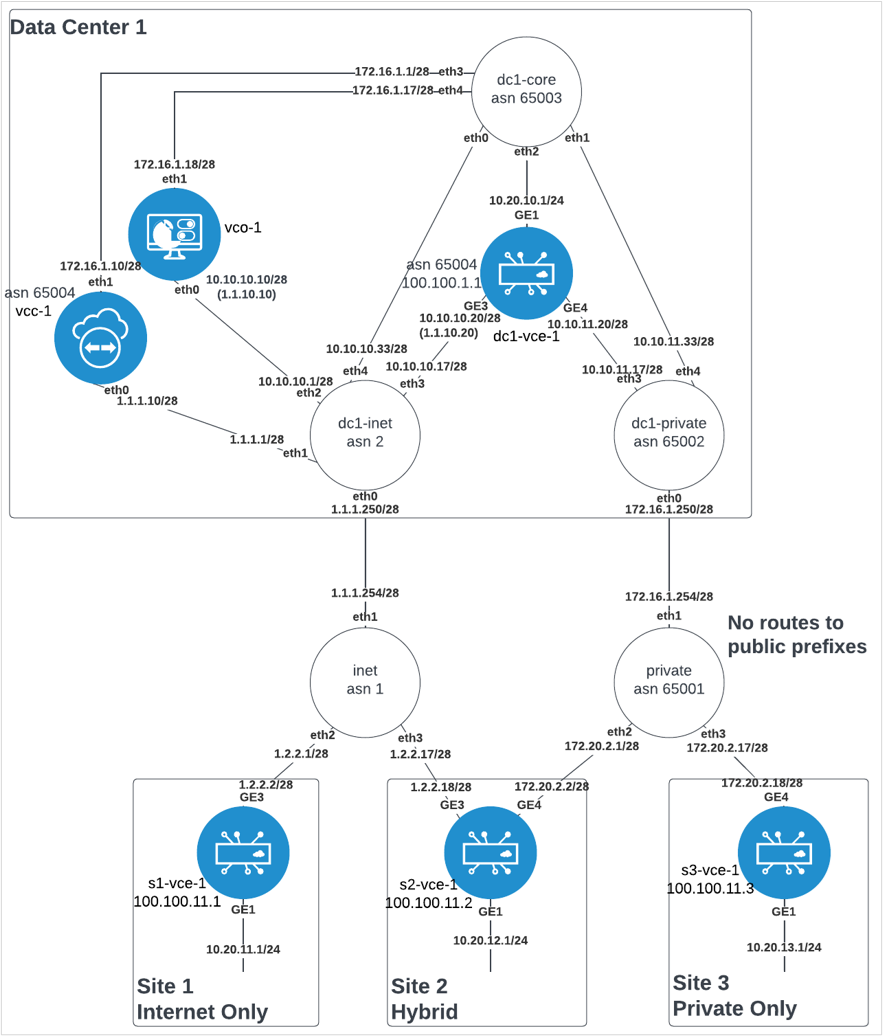
A Sample Minimal Topology
Network Address Translation (NAT)
Network Address Translation (NAT) is used at the Hub Edge. It can be avoided if all components (Orchestrator, Controller, and Edges) are provided public IP addresses directly on their interface, but this is uncommon due to security requirements and limited IPv4 addresses in some networks.
In the minimal topology, the Orchestrator and the Edge(s) are placed behind a NAT boundary. The Controller is placed in front of the NAT boundary. In the example, the dc1-inet underlay router eth0 (internet connection) and eth1 (Controller) interfaces are in front of the NAT boundary, eth2 (Orchestrator), eth3 (Edge) and eth4 (data center) are behind the NAT boundary. This placement of components requires the minimal amount of NAT configuration required. The NATs needed are:
- Orchestrator 1:1 NAT: public IP to private IP translation on all eth0 inbound traffic. The VCOs publicly reachable IP address is 1.1.10.10, but its real IP address behind the NAT boundary is 10.10.10.10. All traffic initiating from and ingressing from the internet with destination IP address of 1.1.10.10 needs to have the destination address translated to 10.10.10.10. This translation must be bidirectional, in that the return traffic with a source IP address of 10.10.10.10 needs to be translated to a source IP address of 1.1.10.10.
The same requirement is necessary for inbound traffic on eth4, as public (internet only) Edges attempting to communicate to Orchestrator using VCOs public IP address (1.1.10.10) will egress the vcc on eth1 and route through the data center core to the internet edge, inbound on eth4.
- Edge 1:1 NAT: public IP to private IP translation on all eth0 inbound traffic. The Edges publicly reachable IP address is 1.1.10.20, but its real IP address behind the NAT boundary is 10.10.10.20. All traffic initiating from and ingressing from the internet with a destination IP address of 1.1.10.20 needs to have the destination address translated to 10.10.10.20. This translation must be bidirectional, in that the return traffic with a source IP address of 10.10.10.20 needs to be translated to a source IP address of 1.1.10.20.
- Edge SNAT: Source Network Address Translation on all eth1 outbound traffic. All traffic initiating from the Edge destined to the Controller (egress eth1) with a source IP address of 10.10.10.20 needs to have the source IP address translated to 1.1.10.20. This translation must be bidirectional, in that the return traffic with a destination address to 1.1.10.20 needs to be translated to a destination IP address of 10.10.10.20.
An example configuration of these NAT rules in vyos:
nat {
    destination {
        rule 10 {
            destination {
                address 1.1.10.10
            }
            inbound-interface eth0
            translation {
                address 10.10.10.10
            }
        }
        rule 15 {
            destination {
                address 1.1.10.10
            }
            inbound-interface eth4
            translation {
                address 10.10.10.10
            }
        }
        rule 20 {
            destination {
                address 1.1.10.20
            }
            inbound-interface eth0
            translation {
                address 10.10.10.20
            }
        }
    }
    source {
        rule 20 {
            outbound-interface eth1
            source {
                address 10.10.10.20
            }
            translation {
                address 1.1.10.20
            }
        }
        rule 999 {
            outbound-interface eth0
            translation {
                address masquerade
            }
        }
    }
}
Routing
- All Hub Edge WAN IP addresses – the sample minimal topology uses 10.10.0.0/16.
- All Spoke Edge Private WAN IP addresses – the sample minimal topology uses 172.20.0.0/16.
- All Edge Loopbacks – the sample minimal topology uses 100.100.0.0/16.
- All Spoke Edge client user subnets – the sample minimal topology uses 10.20.0.0/16.
Orchestrator Routing
The VMware Edge Cloud Orchestrator (VECO, or just Orchestrator) operating system needs to have the following routes:
- Hub Edge WAN IP summary – via eth0 next hop with metric 0.
- Spoke Edge Private WAN IP summary – via eth0 next hop with metric 0.
- Spoke Edge Public WAN IP summary (default route) – via eth0 next hop with metric 0.
- All Edge Loopbacks – via eth0 next hop with metric 0.
- All Spoke Edge client user subnets – via eth1 next hop with metric 0.
- Controller eth1 subnet – via eth1 next hop with metric 0.
Controller Routing
The Controller operating system needs to have the following routes:
- Default route – via eth0 next hop with metric 0
- Default route – via eth1 next hop with metric 5
- Orchestrator eth1 subnet - via eth1 next hop with metric 0
Controller SD-WAN Control Plane Routing
- The Controller control plane injects Orchestrator routes to the overlay for both Orchestrator IPs: 1.1.10.10/32 and 10.10.10.10/32. This draws connections to Orchestrator from the Edge to use the Controller VCMP tunnels.
- The Controller control plane peers BGP on eth1 with its next-hop to dynamically advertise Loopback IP addresses of Edges with VCMP tunnels established. This ensures return traffic from the Orchestrator to the Edges will come back to the Controller to be placed back into the VCMP tunnel.
Connections
Orchestrator Connections
- The Orchestrator uses eth0 for all HTTPS management connections to Edges via the underlay and via the overlay (from Controller tunnels).
- The Orchestrator uses eth1 for all HTTPS user/administrator GUI.
- The Orchestrator-to-Controller communication uses Controller eth1-to-Orchestrator eth1 path.
Controller Connections
- The Controller uses eth0 for all public transport VCMP tunnels, and eth1 for all private transport VCMP tunnels.
Edge Connections
- Edges use their WAN IP address for all activations to the Orchestrator. Private transport Edges use 10.10.10.10 to activate, public transport Edges use 1.1.10.10 to activate. Hybrid Edges can use whichever path to the Orchestrator is available.
- Edges then build VCMP tunnels (UDP 2426) using their WAN IP addresses to the Controller. Public transports build to Controller eth0, and private transports build to Controller eth1.
- Post activation, Edges use their Loopback IP addresses to source all connections to the Orchestrator. The Edge places this connection inside the tunnel to the Controller, using either transport tunnel available. This connection then egresses the Controller through its eth1 connection to the core network destined for the Orchestrator. The Controller leaves the Loopback IP address as the source in tact (no SNAT as with 1-arm Controller). The Orchestrator then replies to the Edge destined to its loopback which is dynamically routable via the Controller eth1 interface to ensure symmetric routing.
Prerequisites
The following are the prequisites needed to deploy an on-premises SD-WAN solution:
- ESXi 6.5.0 or higher.
- Intel Xeon.
- Hyperthreading disabled (for Edge).
- SSD storage supporting 10k or higher IOPS
- Intel NIC with DPDK and SR-IOV support
- VDS, vswitches, and port groups pre-configured
- Encrypted disks are optional
- Plan for 5GB/year/edge
- Linux (such as Ubuntu VM) with genisoimage and tree installed
Cloud-init
- Create YAML files
On the Linux machine, create 3 YAML files each for Orchestrator and Gateway: meta-data, network-config, and user-data. Create 2 files for Edge: user-data and meta-data. Arrange in directory structure to match the following:
On the Linux machine, create 3 yaml files each for Orchestrator and Gateway: meta-data, network-config, and user-data. Create 2 files for Edge: user-data and meta-data. Arrange in directory structure to match the following:Note: The acronym VCG matches to the Gateway (Controller) component; VCE matches to the Edge; and VCO matches to the Orchestrator.isos/ | |--VCG | |--meta-data | |--network-config | |--user-data | |--VCE | |--meta-data | |--user-data | |--VCO | |--meta-data | |--network-config | |--user-data
-
Orchestrator (VCO) Example:
-
user-data
#cloud-config hostname: vco-1 password: Velocloud123 chpasswd: {expire: False} ssh_pwauth: True velocloud: fips_mode: compliant vco: super_users: list: | [email protected]:Velocloud123 remove_default_users: False -
network-config
version: 2 ethernets: eth0: addresses: - 10.10.10.10/28 routes: - to: 0.0.0.0/0 via: 10.10.10.1 metric: 0 nameservers: addresses: [10.10.10.1] eth1: addresses: - 172.16.1.18/28 routes: - to: 10.20.0.0/16 via: 172.16.1.17 metric: 0 - to: 172.16.0.0/12 via: 172.16.1.17 metric: 0 - to: 192.168.0.0/16 via: 172.16.1.17 metric: 0 -
meta-data
instance-id: vco-1
local-hostname: vco-1
-
-
Gateway (VCG) Example:
-
user-data
#cloud-config hostname: vcc-1 password: Velocloud123 chpasswd: {expire: False} ssh_pwauth: True velocloud: fips_mode: compliant -
network-config
version: 2 ethernets: eth0: addresses: - 1.1.1.10/28 routes: - to: 0.0.0.0/0 via: 1.1.1.1 metric: 0 nameservers: addresses: [1.1.1.1] eth1: addresses: - 172.16.1.10/28 routes: - to: 0.0.0.0/0 via: 172.16.1.1 metric: 5 - to: 172.16.1.16/28 via: 172.16.1.1 metric: 0 -
meta-data
instance-id: vcc-1
local-hostname: vcc-1
-
- Edge (VCE) Example
-
user-data
#cloud-config hostname: vce password: Velocloud123 chpasswd: {expire: False} ssh_pwauth: True -
meta-data
instance-id: vce
-
-
- Generate ISO
Example:
cd iso
cd vco
genisoimage -output cdrom.iso -volid cidata -joliet -rock user-data meta-data network-config
cd ..
cd vcc
genisoimage -output cdrom.iso -volid cidata -joliet -rock user-data meta-data network-config
cd ..
cd vce
genisoimage -output cdrom.iso -volid cidata -joliet -rock user-data meta-data
cd ..
The directory structure should look as follows with cdrom.iso added to each directory:Note: The acronym VCG matches to the Gateway component; VCE matches to the Edge; and VCO matches to the Orchestrator.isos/ | |--VCG | |--cdrom.iso | |--meta-data | |--network-config | |--user-data | |--VCE | |--cdrom.iso | |--meta-data | |--user-data | |--VCO | |--cdrom.iso | |--meta-data | |--network-config | |--user-data
- Upload the 3 ISO files to the ESXi datastore
Figure 11. Upload location for ISO files 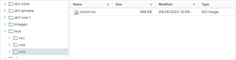
- Orchestrator Deployment - ESXi
Note: Skip to the next section if using vCenter.
- Create/Register VM
- Deploy a virtual machine from an OVF or OVA file, Next
- Provide appropriate name, browse or drag OVA file, Next
- Select storage, Next
- Select appropriate port group for the Orchestrator eth0 interface (VCO also refers to the Orchestrator)
- Select thick provision
- Uncheck power on automatically
- Next
- Finish
- Wait for the OVF import to complete
- Select the newly deployed VM
- Edit
- Add Network Adapter
- Select appropriate port group for Orchestrator eth1 interface
- Expand CD/DVD Drive 1
- Change to Datastore ISO file
- Browse to location of uploaded ISO files, select Orchestrator (or VCO) ISO, Select
- Check Connect at Power On, and Connect
- Save
- Power On VM
- Wait for FIPS mode, the VM will automatically reboot after 5-10 minutes
- Login with
vcadmin/Velocloud123 - Configure NTP at
/etc/ntp.conf(only if private NTP needed, default uses 0.ubuntu.pool.ntp.org)sudo vi /etc/ntp.confpool 10.10.10.1 iburstescape:wq!Sudo service ntp restartSudo ntpq -c peers
- Orchestrator Deployment – vCenter
- Actions, Deploy OVF Template.
- Choose VCO OVA file from local,
Next - Provide appropriate name, select appropriate location
- Select appropriate compute resource,
Next - Review
- Next
- Select storage, thin provision
- Select appropriate port group for the Orchestrator (or, VCO) eth0 interface, Next
- Template values, do not use, leave all empty, Next
- Finish
- Wait for OVF Deploy/Import tasks to complete
- Select VM
- Actions > Edit Settings
- ADD NEW DEVICE
- Network Adapter
- New Network: select appropriate port group for the Orchestrator (or, VCO) eth1 interface
- Expand CD/DVD Drive
- Change to Datastore ISO file
- Browse to ISO, select it, OK
- Check box for Connect at Power on
- OK
- Power On VM
- Wait for FIPS mode, VM will automatically reboot after 5-10 minutes
- Login with
vcadmin/Velocloud123 - Configure NTP at
/etc/ntp.conf(only if private NTP needed, default uses 0.ubuntu.pool.ntp.org)sudo vi /etc/ntp.confpool 10.10.10.1 iburstescape:wq!Sudo service ntp restartSudo ntpq -c peers
- Orchestrator Initial Configuration
- Login to the Orchestrator at https://1.1.10.10/ui/operator with credentials [email protected]/vcadm!n; or [email protected]/Velocloud123; or customized credentials per ISO file are also available if ISO boot was used.
- From the top navigation Select Orchestrator.
- From the left navigation select System Properties.
- Select
network.public.address. - Replace
localhostin value field with1.1.10.10, Save Changes. - Search the top search bar for
websocket. - Select
network.portal.websocket.address. - Value:
172.16.1.18, System Properties. - Search top search bar for
source. - Select
gateway.activation.validate.source. - Change value to
False, Save Changes.
Note: To configure the Orchestrator in a Disaster Recovery (DR) topology, see Configure Orchestrator Disaster Recovery. - Gateway Staging
- From the top navigation select Gateway Management
- From the left navigation select Gateway Pools
- Select Default Pool
- Change Partner Gateway Handoff to: Allow
- SAVE CHANGES
- From the left navigation select Gateways
- New Gateway
- Name: vcc-1
- IPv4 address: 1.1.1.10
- Service State: In Service
- Gateway Pool: Default Pool
- Create
- Select the newly created Gateway vcc-1
- Gateway Roles: Partner Gateway
- Partner Gateway (Advanced Hand Off) Details, delete all default Static Routes
- Static Routes +ADD
- Subnet: 10.10.10.10/32, Cost: 1, Encrypt: Check the box, Handoff: VLAN
- Subnet: 1.1.10.10/32, Cost: 1, Encrypt: Check the box, Handoff: VLAN
- SAVE CHANGES
- Save the activation key from the yellow bar at the top
- Gateway Deployment - vCenter
Note: For a Gateway ESXi install, follow a similar process as outlined in Step 4 for the ESXi Orchestrator.
- Deploy OVF Template.
- Choose VCG OVA file from local. (VCG is the equivalent for Gateway)
- Provide appropriate name, select appropriate location.
- Select appropriate compute resource.
- Review
- Select storage, thick provision.
- Select appropriate port group for Outside, Inside.
- Template values: do not use, leave all empty.
- Next
- Finish
- Wait for OVF Deploy/Import tasks to complete.
- Select VM.
- Actions, Edit Settings
- Expand CD/DVD Drive 1.
- Change to DataStore ISO file.
- Browse to ISO, select, OK.
- Check Connect at Power On, OK.
- Power On VM.
- Wait for FIPS mode to enable, the instance will reboot automatically.
- FIPS is complete when login says
Linux 4.15.0-1113-fips x86_64.vcg-1 login: vcadmin Password: Welcome to Velocloud OS (GNU/Linux 4.15.0-1113-fips x86_64)
- Login with vcadmin/Velocloud123
- Configure NTP at /etc/ntp.conf (only if private NTP needed, default uses 0.ubuntu.pool.ntp.org).
pool 10.10.10.1 iburst
sudo service ntp restart
sudo ntpq -c peers
- Ensure offset is less than or equal to 15ms using:
sudo ntpq-p
- Configure vc_blocked_subnets
cd /opt/vc/etcsudo vi vc_blocked_subnets.json- delete all lines
- insert : {}
- press the escape key
:wq!
- Configure gatewayd
cd /etc/configsudo vi gatewayd- in the wan field (4th line) and geneve field (5th line) substitute eth1 in place of eth0
"wan": ["eth1"],
"geneve": ["eth1"],
- press the escape key
:wq!
-
sudo reboot
- Manually activate
- login with vcadmin/Velocloud123
-
sudo su
-
cd /opt/vc/bin
-
activate.py -I -s 172.16.1.18 <activation key> - a successful activation would output the following:
Activation successful, VCO overridden back to 172.16.1.18
- Orchestrator Operator Profile
Note: For an ESXi installation, follow a process similar to Step 4a for the Orchestrator.
- Login to the Orchestrator User Interface as an Operator.
Note: Make sure the URL includes /operator at the end.
- Top navigation: Edge Image Management
- Left navigation: Software
- Upload Image
- Browse to or drop an appropriate Edge image, for example:
edge-imageupdate-VC_VMDK-x86_64-5.2.0.2-83770177-R5202-20230725-GA-6969b39047
- Done
- Left navigation: Application Maps
- Upload
- Browse to or drop appropriate application map, for example: r5200_app_map.json
- Edit (do not save)
- Rename to version, for example: R5200
- Save Changes
- Top navigation: Administration
- Left navigation: Operator Profiles
- NEW
- Name: R5200-PUBLIC
- Create
- Select newly created R5200
- Ensure Orchestrator Address: IP address
- Ensure Orchestrator IPv4 Address: 1.1.10.10
- Application Map Assignment, JSON File: R5200
- Software Version: Toggled On
- Version: 5.2.0.2
- Save Changes
- Left Navigation: Operator Profiles
- Check the box next to R5200
- DUPLICATE
- Name: R5200-PRIVATE, CREATE
- Select R5200-PRIVATE
- Change Orchestrator IPv4 address to: 10.10.10.10
- SAVE CHANGES
- Login to the Orchestrator User Interface as an Operator.
- Customer Configuration
- Login to the Orchestrator User Interface as an Operator.
Note: Make sure the URL includes /operator at the end.
- Top navigation: Customers & Partners
- Left navigation: Manage Customers
- +NEW CUSTOMER
- Company Name: cust1
- Check the SASE Support Access box
- Check the SASE User Management Access box
- Next
- Administrative Account
- Username: [email protected]
- Password: Velocloud123
- Next
- Services
- Check the SD-WAN box
- Gateway Pool: Default Pool
- Check the Allow Customer to Manage Software box
- Software Image, +ADD
- Select R5200-PRIVATE and R5200-PUBLIC, click the right pointing arrow to move these to the Selected Images
- Select the radio button to the right of R5200-PRIVATE
- Done
- SD-WAN, Edge Licensing, +ADD
- Search for the term ‘POC’
- Select POC | 10Gbps |, click the right pointing arrow to move this license to Selected Edge Licenses
- Save
- Check the box for Feature Access, Stateful Firewall
- ADD CUSTOMER
- Select the newly created ‘cust1’ check box to the left
- At top, select EDIT CUSTOMER SYSTEM SETTINGS
- Left navigation, select Customer Configuration
- Scroll to the bottom and then expand SD-WAN Settings
- Check the box for Distributed Cost Calculation
- Check the box for Use NSD Policy
- Save Changes
- Login to the Orchestrator User Interface as an Operator.
- Partner Gateway Configuration
- Top navigation: customer selected, Global Settings
- Left navigation: Customer Configuration
- Expand Gateway Pool
- Toggle Partner Hand Off to ON
- Configure Hand Off radio button, change to Per Gateway
- Confirm with OK
- Under vcc-1 – Global Segment, click Configure BFD & BGP
- BGP toggle to ON
- Customer ASN: 65004
- Hand Off Interface, Local IP address: 172.16.1.10/28
- Use for Private Tunnels: Check the box
- Advertise Local IP address via BGP: Check the box
- BGP, Neighbor IP: 172.16.1.1
- Neighbor ASN: 65003
- Secure BGP Routes: Check the box
- BGP Inbound Filters, +ADD
- Match type: prefix for IPv4, match value: 0.0.0.0/0, Exact Match: No, Action Type: Deny
- BGP Outbound Filters, +ADD
- Match Type: prefix for IPv4, match value 100.100.0.0/16, Exact Match = No, Action Type: Permit, Action Set: Community: 777:777, Community Additive: Activated
- UPDATE
- SAVE CHANGES
- Quick Start Profile Configuration
- Dark blue navigation bar, select Global Settings Dropdown, select SD-WAN
- Top navigation bar, select Configure
- Left Navigation bar, select Profiles
- Select Quick Start Profile
- Select Firewall tab
- Expand Edge Access
- Console Access: Allow
- SAVE CHANGES
- Select Device Tab
- Expand Connectivity > Interfaces, X out all Edge models not in use
- Select GE1
- Change Capability to Routed
- Disable Underlay Accounting
- Disable Enable WAN Link
- IPv4 Settings > Addressing Type, change to Static
- Check the Advertise box
- Uncheck the NAT Direct Traffic box
- SAVE
- Repeat steps k-through-r for GE2
- Select GE2, uncheck the Interface Enabled box
- SAVE
- SAVE CHANGES
- Expand VLAN, select 1-Corporate, DELETE
- Confirm DELETE
- Under Connectivity > Interfaces, select GE3
- IPv4 Settings > Addressing Type: Static, then SAVE
- Select GE4
- IPv4 Settings > Addressing Type: Static
- WAN Link: User Defined
- SAVE
- Under VPN Services, Expand Gateway Handoff Assignment, +SELECT GATEWAYS
- Check vcc-1, UPDATE
- Under VPN Services, toggle Cloud VPN to ON
- SAVE CHANGES
- Hub Edge Profile
- Configure > Profiles
- Check the box next to Quick Start Profile
- DUPLICATE
- Name: Hub, CREATE
- Hub Edge Staging
- Top navigation: Configure
- Left navigation: Edges
- +ADD EDGE
- Name: dc1-vce-1
- Model: select as appropriate
- Profile: Hub
- Edge License: POC
- NEXT
- ADD EDGE
- Expand Loopback Interfaces, +ADD
- Interface ID: 1
- IPv4 Address: 100.100.1.1, ADD
- Expand Management Traffic
- Source Interface: LO1
- Expand Interfaces section
- Select GE1
- IPv4 settings, enter IP address: 10.10.11.1
- Set Cidr prefix: 24
- SAVE
- Select GE3
- IPv4 settings, enter IP address: 10.10.10.20
- CIDR Prefix: 28
- Gateway: 10.10.10.17
- SAVE
- Select GE4
- IPv4 settings, enter IP address: 10.10.11.20
- CIDR Prefix: 28
- Gateway: 10.10.11.17
- SAVE
- WAN Link Configuration section, +ADD USER DEFINED WAN LINK
- Link Type: Private
- Name: Private
- SD-WAN Service Reachable: Checked
- SD-WAN Service Reachable Backup: Uncheck the box
- Interfaces: GE4
- ADD LINK
- SAVE CHANGES
- Copy the activation key from the yellow bar at the top
- Hub Edge BGP Configuration
Caution: You must apply proper route maps to prevents loops to the Orchestrator.Important: The following steps are mandatory and must be done prior to activating the Hub Edge.
- Configure > Edges
- Select dc1-vce-1
- BGP: Check Override, Toggle ON, Expand
- Local ASN: 65004
- Filter List: +ADD
- Filter Name: outbound
- Filter Rules: 1 Rule, click on the link
- Match type: Prefix for IPv4
- Match value: 10.10.10.10/32
- Exact Match: check the box
- Action Type: Deny
- Check first rule, CLONE
- Match Type: Prefix for IPv4
- Match Value: 1.1.10.10/32
- Exact Match: check the box
- Action Type: Deny
- +ADD
- Match Type: Prefix for IPv4
- Match Value: 100.100.0.0/16
- Exact Match: do not check the box
- Action Type: Deny
- +ADD
- Match Type: Prefix for IPv4
- Match Value: 0.0.0.0/0
- Exact Match: do not check the box
- Action Type: Permit
- Action Set: Community 777:777
- Community Additive: Activated checked
- SUBMIT
- RESULT:
Figure 12. Outbound Filter Rules 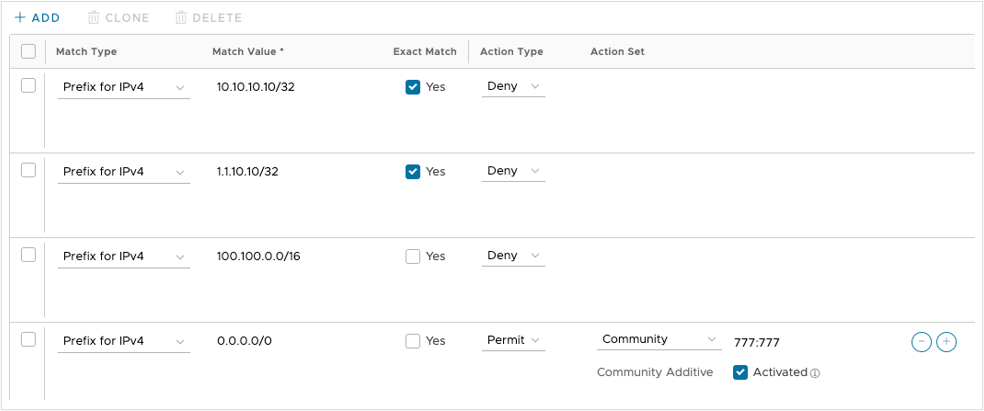
- Filter List, +ADD
- Filter Name: inbound
- Filter Rules: 1 Rule, click on the link
- Match type: Community
- Match Value: 777:777
- Exact Match: No
- Action Type: Deny
- +ADD
- Match Type: Prefix for IPv4
- Match Value: 0.0.0.0/0
- Exact Match: check the box
- Action Type: permit
- +ADD
- Match Type: Prefix for IPv4
- Match Value: 0.0.0.0/0
- Exact Match: do not check the box
- Action Type: Deny
- SUBMIT
- RESULT:
Figure 13. Inbound Filter Rules 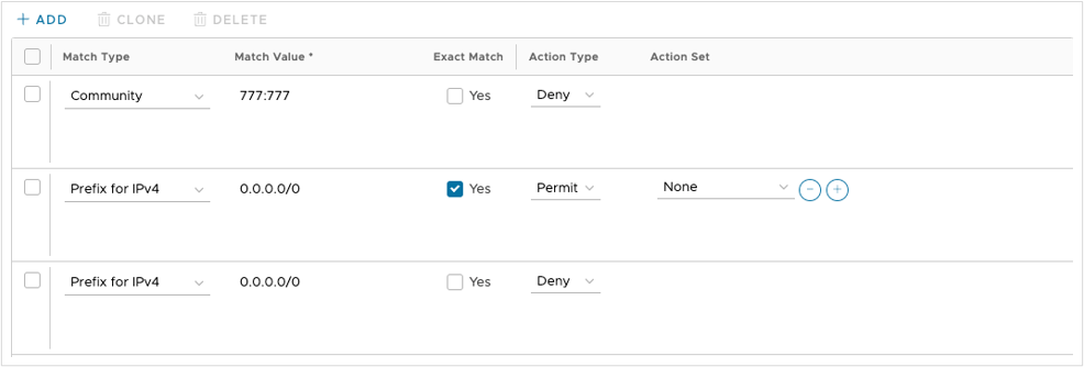
- Neighbors, +ADD
- Neighbor IP: 10.10.11.2
- ASN: 65003
- Inbound Filter: inbound
- Outbound Filter: outbound
- SAVE CHANGES
- Hub Edge Deployment
Note: For an ESXi installation, follow a process similar to Step 4a for the Orchestrator. Mount an ISO instead of using the OVA wizard template and use the
set_wan_config.shcommand to set WAN IP addresses.- Login to vCenter
- Deploy OVF Template.
- Choose Edge (that is, VCE) OVA file from local
- Provide an appropriate name, select an appropriate location
- Select an appropriate compute resource
- Review
- Select storage, thick provision
- Select appropriate port groups:
- GE1: dc1-lan-pg
- GE2: dc1-lan-pg
- GE3: dc1-inet-pg
- Next
- Template values:
- Orchestrator address: 10.10.10.10
- Activation code: (paste from previous)
- Check the box to ignore Orchestrator certificate validation errors
- Default Users Password: Velocloud123
- DNS1: 10.10.10.17
- DNS2: 10.10.11.17
- GE3 interface IPv4 allocation: STATIC
- GE3 interface IPv4: 10.10.10.20
- GE3 interface IPv4 subnet mask: 255.255.255.240
- GE3 interface default gateway: 10.10.10.17
- GE4 interface IPv4 allocation: STATIC
- GE4 interface IPv4: 10.10.11.20
- GE4 interface IPv4 subnet mask: 255.255.255.240
- GE4 interface default gateway: 10.10.11.17
- NEXT
- FINISH
- Wait for OVF Deploy/Import tasks to complete
- Power On VM
- Login with
vcadmin/Velocloud123 - If needed (such as with an ESXi deployment), manually activate:
activate.py -i -s 1.1.10.10 <activation key>
- Spoke Edge Profile
- Dark blue navigation bar, select Global Settings Dropdown, select SD-WAN
- Top navigation bar, select Configure
- Left Navigation bar, select Profiles
- Select the checkbox next to Hub Profile
- Duplicate
- Name: Spoke-Hybrid
- Create
- Select Device tab
- Expand Connectivity > Interfaces, select appropriate SD-WAN Edge models
- Under VPN Services, check the box next to Branch to Hub Site (permanent VPN): Enable Branch to Hubs
- On the right, select Edit Hubs
- Select the check box next to dc1-vce-1, click the arrow that moves it rightward on the Hubs list
- UPDATE HUBS
- SAVE CHANGES
- Configure > Profiles
- Check the box next to Spoke-Hybrid
- DUPLICATE
- Name: Spoke-Public
- CREATE
- On the Configure > Device tab
- Expand Interfaces
- Select GE4
- Change Addressing Type to DHCP
- Change WAN Link to Auto-Detect
- SAVE
- SAVE CHANGES
- Configure > Profiles
- Check the box next to Spoke-Hybrid
- DUPLICATE
- Name: Spoke-Private
- CREATE
- Back on the Configure > Device tab
- Expand the Interfaces section
- Select GE3
- Change Addressing Type: DHCP
- SAVE
- SAVE CHANGES
- Public Spoke Staging
- Configure > Edges
- +ADD EDGE
- Name: s1
- Model: select as appropriate
- Profile: Spoke-Public
- Edge License: POC
- NEXT
- ADD EDGE
- Expand Loopback Interfaces
- +ADD
- Interface ID: 1
- IPv4 address: 100.100.11.1
- ADD
- Expand the Management Traffic section
- Change Source Interface: Lo1
- Expand the Interfaces section
- Select GE1
- IPv4 Settings, IP Address: 10.20.11.1
- Cidr prefix: 24
- SAVE
- Expand the Interfaces section
- Select GE3
- IPv4 settings, IP address: 1.2.2.2
- CIDR Prefix: 28
- Gateway: 1.2.2.1
- SAVE
- SAVE CHANGES
- Copy the activation key from the yellow bar at the top
- Configure > Edges
- Check the box next to s1
- MORE
- Click Assign Operator Profile
- Change to R5200-PUBLIC
- ASSIGN
- Spoke Deployment
Note: For an ESXi installation, follow a process similar to Step 4a for the Orchestrator. Mount an ISO instead of using the OVA wizard template and use the
set_wan_config.shcommand to set WAN IP addresses.- Login to vCenter
- Deploy OVF Template
- Choose the Edge (VCE) OVA file from local
- Provide an appropriate name, select an appropriate location
- Select an appropriate compute resource
- Review
- Select storage, thick provision
- Select appropriate port groups
- GE1: s1-lan-pg
- GE2: s1-lan-pg
- GE3: inet-s1-pg
- Next
- Template Values:
- Orchestrator address: 1.1.10.10
- Activation code: (paste from section 14 step 21)
- Check the box to ignore VCO (Orchestrator) certificate validation errors
- Default Users Password: Velocloud123
- DNS1: 1.2.2.1
- DNS2: 1.2.2.1
- GE3 interface IPv4 allocation: STATIC
- GE3 interface IPv4: 1.2.2.2
- GE3 interface IPv4 subnet mask: 255.255.255.240
- GE3 interface default gateway: 1.2.2.1
- NEXT
- FINISH
- Wait for the OVF Deploy/Import tasks to complete
- Actions > Edit Settings
- Uncheck the box for Connected for Network Adapter 4
- Power On VM
- Login with
vcadmin/Velocloud123 - If needed, manually activate as follows:
activate.py -i -s 1.1.10.10 <activation key>
