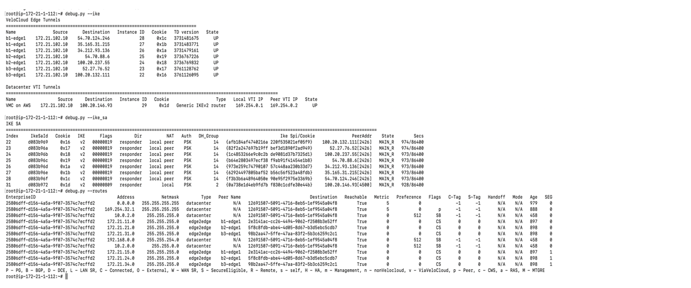
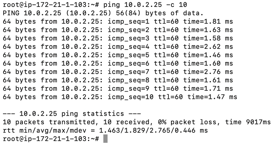
This section provides a brief overview and detailed procedures to configure route based NSD via Gateway to the VMware Cloud AWS Gateway.
Route Based NSD Via Gateway to VMware Cloud AWS Gateway Overview
The figure below illustrates the Integration of VMware SD-WAN and VMware Cloud on AWS, which uses IPSec connectivity between the VMware SD-WAN Gateway and the VMware Cloud Gateway.

Procedure
This section provides step-by-step procedures on how to achieve connectivity between an SDWAN Gateway and a VMware Cloud Gateway.
- Log into the VMware Cloud Console based on the URL for your SDDC organization (The VMware Cloud Services Login Page). On the Cloud Services Platform, select VMware Cloud on AWS.
- Find Public IP used for VPN connectivity by clicking the Networking and Security tab. The VPN Public IP displays below the Overview pane.
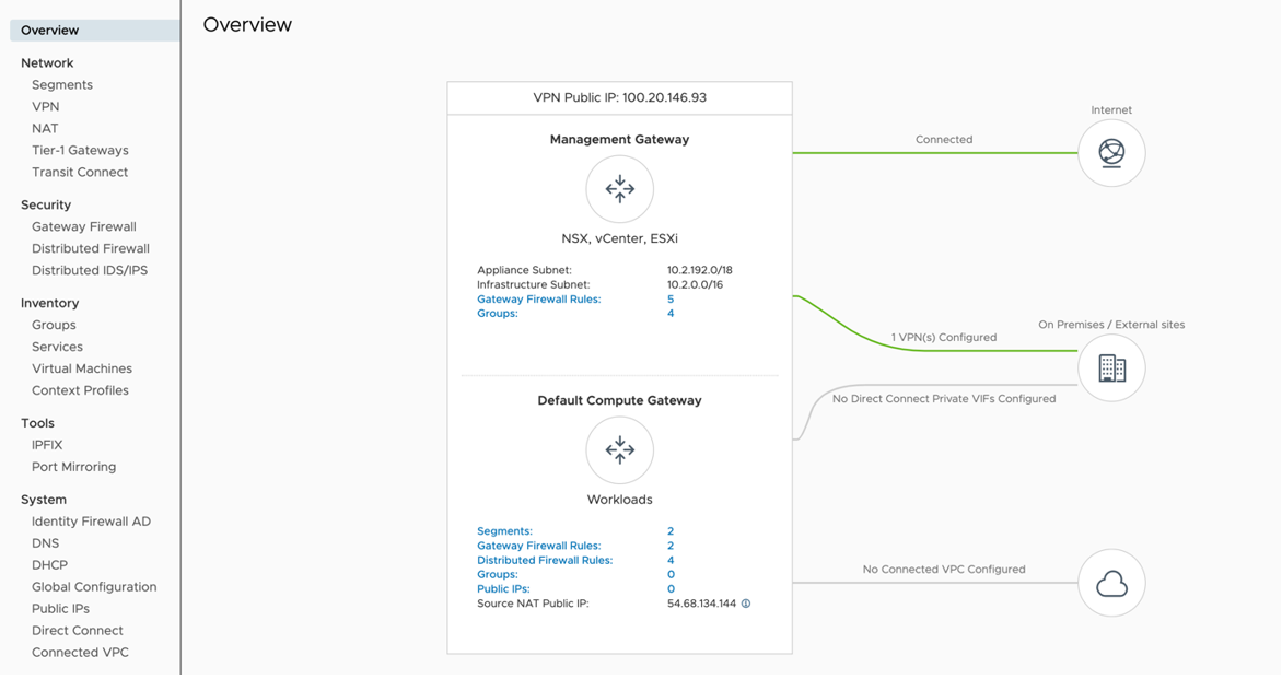
- Determine the networks/subnets for traffic encryption selection (interesting traffic) and write them down. These should originate from Segments in Networking/Security in the VMware Cloud. (Locate this by clicking Segments, under Network.)
- Log into the SD-WAN Orchestrator and verify that SD-WAN Edges are displayed (a green status icon will be displayed next to them).
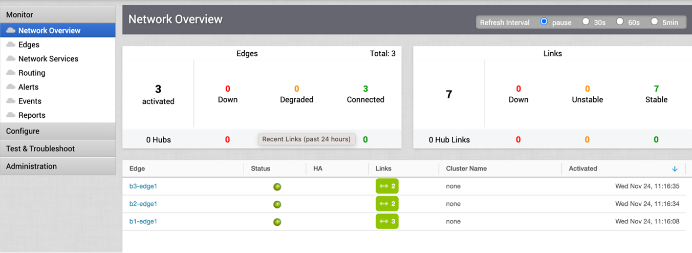
- Go to the Configure tab and click Network Services. Under Non SD-WAN Destination via Gateway, click the New button.

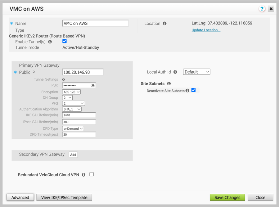
- Provide a name for the Non SD-WAN Destination via Gateway. Select the type, in this case, Generic IKEv2 Router (Route Based VPN), and Enter the Public IP from the VMC obtained in Step 2, and click Next.

- Click the Advanced button, and complete the following:
- Change to the desired PSK.
- Ensure encryption set to AES 128.
- Change DH group to 2.
- Enable PFS to 2.
- Auth Algorithm set to SHA 1.
- Deactivate site subnet, since subnets are learned via BGP. (If BGP is not configured then add site subnets captured at step 3, like static route).
- Click the check box next to Enable Tunnels.
- Click Save Changes.
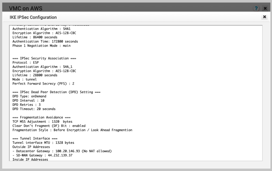
- Click View IKE/IPSec Template and copy the information into a text file, and then close the window.
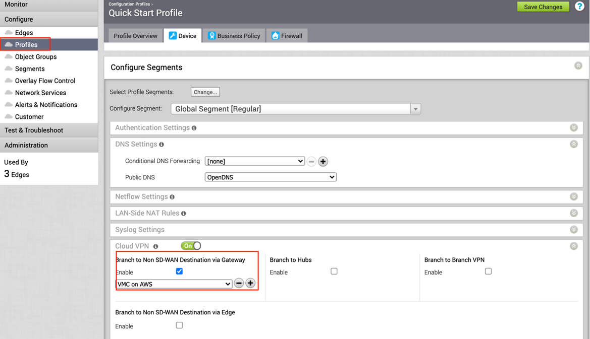
- Along the left pane, click Configure > Profiles.

- Go to the profile for the associated SD-WAN Edge and click the appropriate Profile.
- Under the correct Profile complete the following.
- Go to the Device tab, under Cloud VPN and Branch to Non SD-WAN Destination via Gateway, click the checkbox next to Enable.
- In the drop-down menu, select the NSD via Gateway that was created (beginning in Step 6).
- Click the Save Changes button at the top of the screen.
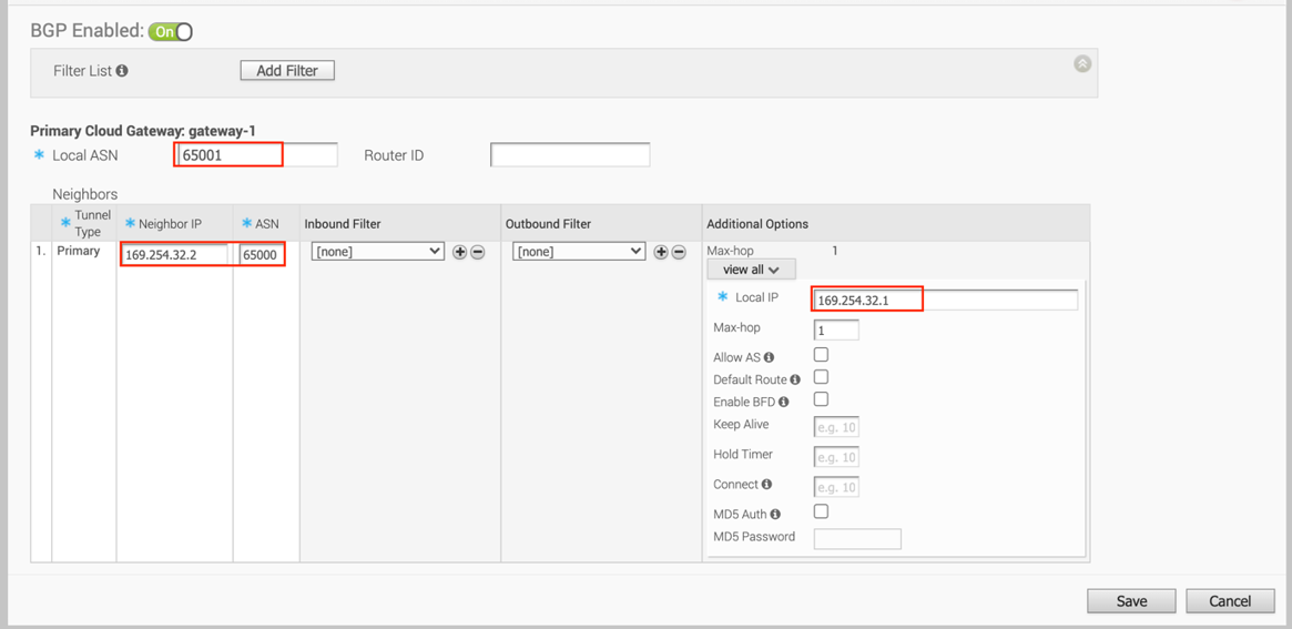
- Go to the Network service page, click the BGP button in NSD via Gateway service area.

- Configure BGP parameters:
- Configure Local ASN 65001
- Neighbor IP– 169.254.32.2 c) Peer ASN – 65000 (VMC default ASN is 65000)
- Local IP – 169.254.32.1
Note: It is recommended to use a /30 CIDR from 169.254.0.0/16 subnet excluding following VMC reserved addresses - 169.254.0.0-169.254.31.255, 169.254.101.0-169.254.101.3
- Log into the VMware Cloud Console.
- Go to Networking and Security and click the VPN tab. In the VPN area, select Route Based VPN, and click Add VPN.

- Provide a name for the Route Based VPN and configure the following.
- Choose a name. (Choose a name that starts with “To_SDWAN_Gateway,” so the VPN can be easily identified during troubleshooting and future support).
- Select the Public IP.
- Enter the remote Public IP.
- Enter the remote Private IP. NOTE: This will require a call to GSS Support, please refer to the following KB article, and mention the KB ID when contacting Support. https:// ikb.vmware.com/s/article/78196.
- Specify the BGP local IP.
- Specify the BGP remote IP.
- Under Tunnel Encryption, select AES 128.
- Under Tunnel Digest Algorithm, select SHA1.
- Make sure Perfect Forward Secrecy is set to Enabled.
- Enter the PSK, to match Step 7A.
- Under IKE Encryption, select AES 128.
- Under IKE Digest Algorithm, select SHA 1.
- Under IKE Type, select IKEv2.
- Under Diffie Hellman, select Group 2.
- Click Save.
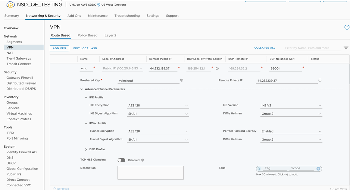
- Once the configuration is complete, the tunnel is automatically activated and will proceed to negotiate the IKE Phase 1 and Phase 2 parameters with the peer, which is the SD-WAN Gateway.

- Once the tunnel displays (green), verify that the NSD via Gateway tunnel/BGP status in the SD-WAN Orchestrator (go to Monitor > Network Services).
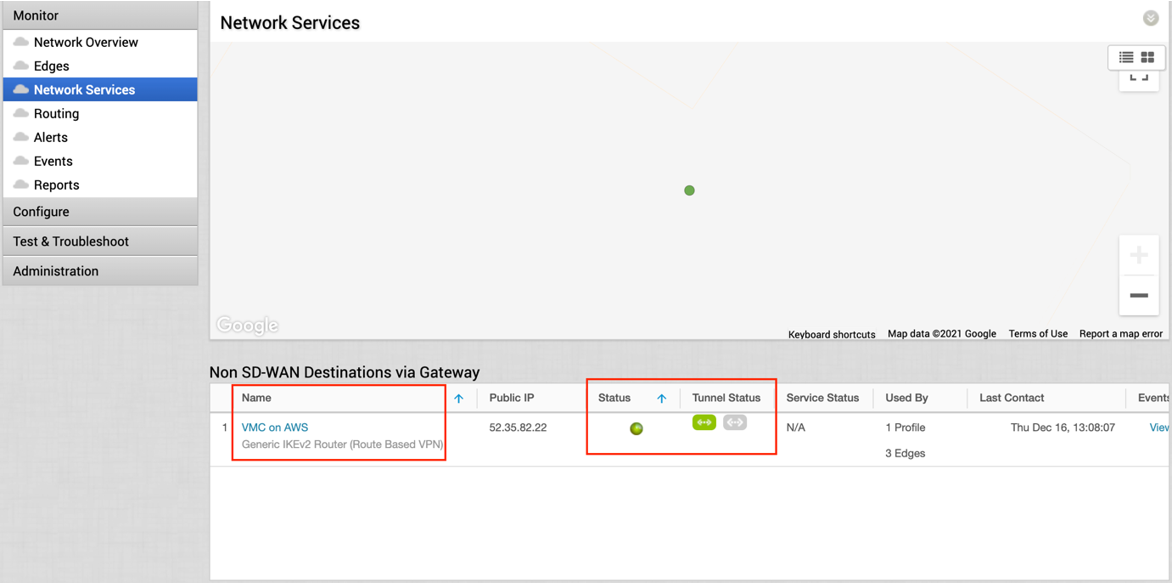

- Start a ping from a client connected at each end towards the opposite client, and verify ping reachability. The tunnel configuration has been completed and verified.
