


Sites and Views provide the ability to display connections between devices. Connection types are identified by different line styles in your View or Site. Connections can be displayed in two formats:
| Physically |
This displays clouds for certain WAN technologies, giving a layer-2 visualization of your network. |
| Logically |
This provides layer-3 visualization. |
Because of the hierarchy of sites and the association rules of devices in views, this is where the similarity of connections ends between the two.
Views
Views are flat in nature, having no relation to other views. Connections in Views are visible only between devices within that view.
Since a required relationship between any device in a view is not needed, you could create a view in which there are no connection associations between any of the devices.
A good example of this would be a view containing all firewall devices in an enterprise. Each firewall could be providing outbound access from the enterprise, and have no actual direct connectivity to each other. In this view, the diagram would display an icon for each device, but there would be no connections.
Sites
Sites, because of their hierarchical relationship and physical nature, have a complex connection construct. This is due to the three-dimensional effect created by the site hierarchy when in a site diagram.
Before explaining the concept of connections in sites, it is important to remember that ALL connections in Network Configuration Manager are ultimately device-to-device. Also, connector lines in a diagram can represent a single connection, or at times, a group of connections conveniently associated by a connection type.
Imagine a site diagram containing three devices and two other sites. The two sites would be considered children, or sub-sites, of the current site, as they are 'down' the hierarchy chain. In this imagined diagram, it is possible that two of the visible devices could have connections (for example, Ethernet, or Frame Relay) between them, which would create a device-to-device connector.
One of the devices could have a connection to a device contained in one of the sub-sites, which would require a device-to-site connector. It is also possible that a device contained in the first sub-site could be directly connected to a device in the second sub-site.
In the current view, the diagram would construct a site-to-site connector. Consider also that the devices in the sub-sites may not live at the top of that site level, but be nested in other sub-sites down the hierarchy. Regardless, the same connector would be constructed.
Finally, a device in the current diagram or contained in one of the sub-sites, could be directly connected to a device in a site, in a completely different branch of the site hierarchy, or 'up' the hierarchy. In both of these cases, the terminating device or site would not be visible in the current diagram. In this case, a device-to-off-site, or site-to-off-site connector would be constructed.
Within a site diagram, there are five connector relationships:
| Device-to-Site Are connections between devices contained in the hierarchy. |
|
| Device-to-Device Shows connections from one device to another device. |
|
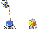
| Device-to-Off-site Are connections to devices outside of the site hierarchy. These connections are identified by an off-site icon. |
|
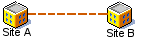
| Site-to-Site Shows connections from one site to another site. |
|
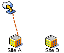
| Site-to-Off-site Are connections to site levels within the site hierarchy. These connections are identified by an Off-site icon. |
|


Since it is assumed that once a site hierarchy is constructed, there will be few physical changes.
The recalculation of connections in a site hierarchy is completed as a nightly batch process, at approximately 4:00 A.M.
This schedule can be changed, depending on the requirements of your network. As changes are made to networks during regular use, a flag is used to indicate that site diagrams are due for an update. When a site diagram is refreshed, it is transparent to the user. Depending on the number of devices, the refresh may be time consuming.
