


This topic describes how to define a network profile to configure shared and dedicated Tier-1 router topologies for VMware Tanzu Kubernetes Grid Integrated Edition (TKGI) provisioned Kubernetes clusters on vSphere with NSX.
This topic also explains how to define a network profile that overrides the Shared Tier-1 topology default, to specify Dedicated Tier-1 topology for TKGI clusters.
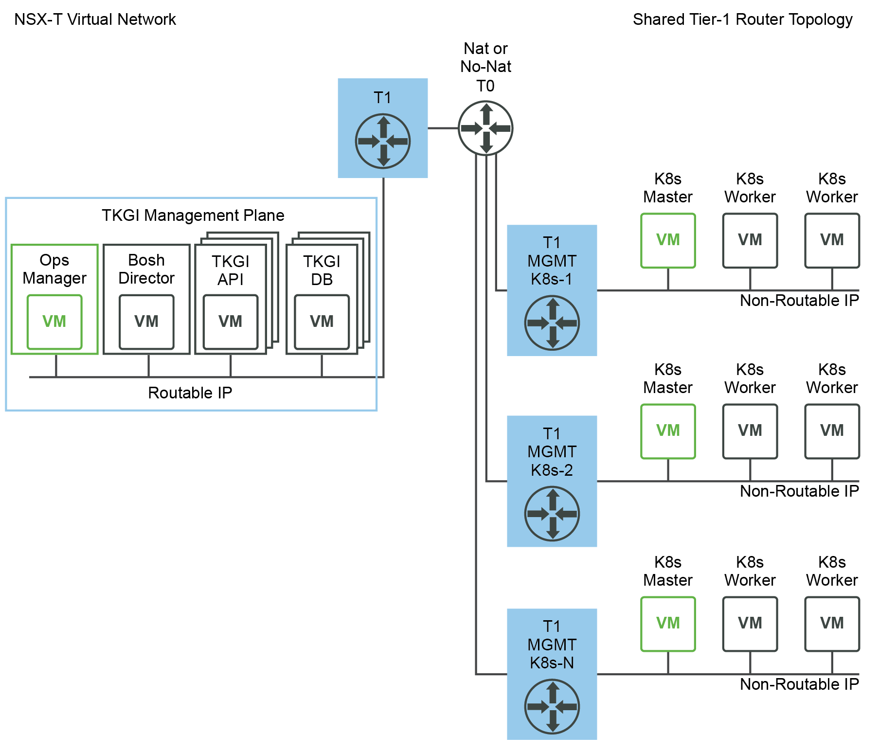
Shared Tier-1 Topology
By default, Kubernetes clusters in Tanzu Kubernetes Grid Integrated Edition with NSX-T have the Shared Tier-1 network topology, in which each cluster shares a single Tier-1 router for its external-facing components: the Kubernetes node, namespace, and NSX-T load balancer.
Note: The Shared Tier-1 topology requires NSX-T Data Center v2.5.
This topology uses a single, shared Tier-1 switch and router for each Kubernetes cluster. The shared Tier-1 model only uses one Tier-1 router and multiple logical switches connected to the shared Tier-1 to connect all Kubernetes cluster components, including:
- Kubernetes Nodes Networks
- Kubernetes Namespaces
-
NSX-T load balancer instances allocated for the Kubernetes cluster
Comparison to Dedicated Tier-1
Unlike the Dedicated Tier-1 Topology, the shared Tier-1 model configures any necessary NAT rules (if using NAT mode) on the single Tier-1 router directly. The Tier-0 router is not used for any NAT configuration. As a result, the Tier-0 router can operate in Active-Active mode if all Kubernetes clusters are deployed using the Shared Tier-1 model.
The Shared Tier-1 model enables higher scale numbers for TKGI as the number of NSX-T objects allocated per Kubernetes cluster is drastically reduced, in comparison to dedicated Tier-1. The advantage of the shared Tier-1 topology is that you can increase the number of NSX-T objects that can be supported in a given cluster.
Dedicated Tier-1 Topology
When you provision a Kubernetes cluster with a network profile that overrides the Shared Tier-1 topology, Tanzu Kubernetes Grid Integrated Edition creates following NSX-T objects:
- 1 Logical Switch and Tier-1 Router for each Kubernetes Nodes subnet
- 1 Logical Switch and Tier-1 Router for each Kubernetes namespace
-
1 Logical Switch and Tier-1 Router each NSX-T Load Balancer that is allocated for the Kubernetes cluster

As depicted above, the result is that a given Kubernetes cluster will run several Tier-1 switches and routers in its topology.
Network Profile for Dedicated Tier-1 Topology
To create clusters with Dedicated Tier-1 topology, you define and use a network profile that overrides the default Shared Tier-1 topology by setting the single_tier_topology key to false.
Shown below is an example network profile that deactivates the Shared Tier-1 Router for Kubernetes clusters:
{
  "name": "example-network-profile-shared-t1",
  "description": "Shared-Tier-1 topology network profile",
  "parameters": {
    "single_tier_topology": false
  }
}
To create a Shared Tier-1 network profile, see Create Network Profile.
To create a cluster using a Shared Tier-1 network profile, see Create a Cluster with a Network Profile.
Implementing a Shared Tier-1 Topology in a Multi-Tier-0 Environment
In a Shared Tier-1 Router topology, all Kubernetes cluster traffic is automatically NATed in the single Tier-1 router that services that cluster. However, in a Multi-Tier-0 environment, traffic from Kubernetes Node Networks to the Shared Tier-0 Router cannot be NATed.
To implement a Shared Tier-1 topology in a Multi-Tier-0 environment, use the infrastructure_networks field in the network profile and include the subnets where your infrastructure is running. During Kubernetes cluster creation, Tanzu Kubernetes Grid Integrated Edition will add a NO_SNAT rule from the Node Network to subnets specified in the infrastructure_networks field.
In the following example network profile, the infrastructure-networks field includes three subnets for which NO_SNAT rules will be created. These subnets map to the PKS Control Plane (30.0.0.0/24), vCenter and NSX-T VMs (192.168.111.0/24), and the Nodes DNS server (192.168.115.1).
{
  "name": "tenant-A-shared-T1",
  "description": "Example Network Profile for Tenant A Shared Tier-1 Router Topology",
  "parameters": {
    "t0_router_id": "a6addd27-24ce-469a-979e-cf742a19ef5c",
    "fip_pool_ids": [
      "a8b7f715-42f0-46bf-a4f2-1599c55058b6" ],
    "pod_ip_block_ids": [
      "edd59bf6-ff04-420c-88de-2c43d47f7130" ],
    "infrastructure_networks": [
      "30.0.0.0/24",
      "192.168.111.0/24",
      "192.168.115.1"
    ],
    "single_tier_topology": true
  }
}
