


This topic describes how to deploy a load balancer for the NSX Management Cluster for VMware Tanzu Kubernetes Grid Integrated Edition (TKGI).
About the NSX-T Management Cluster
NSX-T provides a converged management and control plane that is referred to as the NSX-T Management Cluster. The architecture delivers high availability of the NSX-T Manager node, reduces the likelihood of operation failures of NSX-T, and provides API and UI clients with multiple endpoints or a single VIP for high availability.
While using a VIP to access the NSX-T Management layer provides high-availability, it does not balance the workload. To avoid overloading a single NSX-T Manager, which might be the case when HA VIP addressing is used, an NSX-T load balancer can be provisioned to allow NCP and other components orchestrated by Tanzu Kubernetes Grid Integrated Edition to distribute load efficiently among NSX-T Manager nodes.
The diagram below shows an external load balancer fronting the NSX-T Manager nodes. The load balancer is deployed within the NSX-T environment and intercepts requests to the NSX-T Management Cluster. The load balancer selects one of the NSX-T Manager nodes to handle the request and rewrites the destination IP address to reflect the selection.
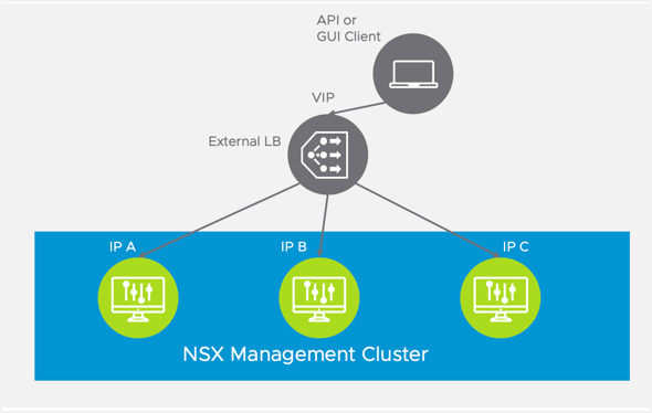
Note: The load balancer VIP load balances traffic to all NSX-T Manager instances in round robin fashion. A Cluster HA VIP, on the other hand, only sends traffic one of the NSX-T Manager instances that is mapped to the Cluster IP VIP; the other NSX-T Manager instances do not receive any traffic.
For scalability, deploy a load balancer in front of the NSX-T Manager nodes. When provisioning the load balancer, you configure a virtual server on the load balancer, and associate a virtual IP address with the virtual server. This load balancer VIP can be used as the entry-point for TKGI- and NCP-related API requests on the NSX-T Control Plane. The virtual server includes a member pool where all NSX-T Management Cluster nodes belong. Additionally, health monitoring is enabled for the member pool to quickly and efficiently address potential node failures detected among the NSX-T Management Cluster.
Provision the NSX-T Load Balancer for the Management Cluster
To provision the load balancer for the NSX-T Management Cluster, complete the following steps.
Step 1: Log in to an NSX-T Manager Node
- Log in to an NSX-T Manager Node.
Note: You can connect to any NSX-T Manager Node in the management cluster to provision the load balancer.
- Select the Advanced Networking & Security tab.
Note: You must use the Advanced Networking and Security tab in NSX-T Manager to create, read, update, and delete all NSX-T networking objects used for Tanzu Kubernetes Grid Integrated Edition.
Step 2: Configure a Logical Switch
Add and configure a new logical switch for the load balancer.
- Select Switching.
- Click Add.
- Configure the logical switch:
- Name: Enter a name for the logical switch, such as
LS-NSX-T-EXTERNAL-LB. - Transport Zone: Select the overlay transport zone, such as
TZ-Overlay.
- Name: Enter a name for the logical switch, such as
- Click Add.
Step 3: Configure a Tier-1 Logical Router
Configure a new Tier-1 Router. Create the Tier-1 Router on the same Edge Cluster where the Tier-0 Router that provides external connectivity to vCenter and NSX-T Manager is located.
- Select Routers.
- Click Add > Tier-1 Router.
- Configure the new Tier-1 Router and click Add.
- Name:
T1-NSX-T-EXTERNAL-LB, for example. - Tier-0 Router: Connect the Tier-1 Router to the Tier-0 Router, for example
Shared-T0. - Edge Cluster: Select the same Edge Cluster where the Tier-0 Router is located, such as
edgecluster1. - Edge Cluster Members: Select
nsx-edge-1-tnandnsx-edge-2-tn, for example.
- Name:
Step 4: Advertise the Routes
Configure Route Advertisement for the Tier-1 Router.
- Select the Tier-1 Router.
- Select the Routing tab.
- Select Route Advertisement > Edit.
- Enable Route Advertisement for all load balancer VIP routes for the Tier-1 Router:
- Status:
Enabled. - Advertise all LB VIP routes:
Yes. - Advertise all LB SNAT IP routes:
Yes. - Click Save
- Status:
Step 5: Verify Router and Switch Configuration
Verify successful creation and configuration of the logical switch and router.
- Select the Tier-1 Router.
- Select the Configuration tab and the Ports option.
- Verify that the router has a single linked port connecting the Tier-1 Router to the Tier-0 Router.
Step 6: Configure a Small Load Balancer
Create a new small-size Load Balancer and attach it to the Tier1 router previously created.
Note: The small-size load balancer is suitable for the NSX-T Management Cluster load balancer. Make sure you have enough Edge Cluster resources to provision a small load balancer.
- Select Load Balancers.
- Click Add.
- Enter a Name for the load balancer.
- Select the SMALL size load balancer.
- Click OK.
Step 7: Attach the Load Balancer to the Router
Attach the load balancer to the Tier-1 Router previously created.
- Select the load balancer you just provisioned.
- Select the Overview tab.
- Select Attachment > Edit.
- Tier-1 Logical Router: Enter the name of the Tier-1 Router you configured, for example
T1-NSX-T-EXTERNAL-LB. - Click OK.
Step 8: Configure a Virtual Server
Add and configure a virtual server for the load balancer.
- Select Load Balancers > Virtual Servers.
- Click Add.
Configure General Properties for the virtual server:
- Name:
VS-NSX-T-EXTERNAL-LB. - Application Types:
Layer 4 TCP. - Application Profile:
default-tcp-lb-app-profile. - Access Log:
Deactivated. - Click Next
Configure Virtual Server Identifiers for the virtual server:
- IP Address: Enter an IP address from the floating pool, such as
10.40.14.250. - Port:
443. - Click Next.
Configure Virtual Server Pool for the virtual server:
- Click Create a New Server Pool.
Configure General Properties for the server pool:
- Name: For example
NSX-T-MGRS-SRV-POOL. - Load Balancing Algorithm:
ROUND_ROBIN. - Click Next
Configure SNAT Translation for the server pool:
- Translation Mode: IP List
- IP address: Enter the Virtual Server IP (VIP) address here, for example
10.40.14.250. - Click Next.
Configure Pool Members for the server pool:
- Membership Type:
Static. - Static Membership: Add all 3 NSX-T Managers as members by entering the node name, IP address, and port (443) for each node.
- Click Next.
Configure Health Monitors:
- We will create the Health Monitors separately.
- Click Finish.
Back at the Server Pool screen, click Next.
Configure Load Balancing Profiles for the load balancer:
- Persistence Profile > Source IP: Select
default-source-ip-lb-persistence-profile. - Click Finish.
Note: If a proxy is used between the NSX-T Management Cluster and the TKGI Management Plane, do not configure a persistence profile.
Step 9: Attach the Virtual Server to the Load Balancer
Attach the virtual switch to the NSX-T load balancer.
- In the Load Balancing panel, select the Virtual Server you created.
- Select the Load Balancers tab.
- Click Attach.
- Load Balancer: Select the load balancer to attach, such as
NSX-T-EXTERNAL-LB. - Click OK.
Step 10: Verify the Load Balancer.
Once the load balancer is configured, verify it by doing the following:
- Ping the NSX-T load balancer VIP address from your local machine.
- Access the NSX-T Manager interface using the load balancer VIP address, for example
https://10.40.14.250.
Note: The URL redirects to the same NSX-T Manager. Persistence is done on the source IP based on the persistence profile you selected.
Step 11: Create an Active Health Monitor (HM)
Create a new Active Health Monitor (HM) for NSX-T Management Cluster members using the NSX-T Health Check protocol.
- Select Load Balancers > Server Pools.
- Select the server pool you created. For example,
NSX-T-MGRS-SRV-POOL. - Select the Overview tab.
- Click Health Monitor > Edit.
- Click Create a new active monitor.
Configure Monitor Properties:
- Name:
NSX-T-Mgr-Health-Monitor. - Health Check Protocol:
LbHttpsMonitor. - Monitoring Port:
443.
Configure Health Check Parameters.
Configure the new Active HM with specific HTTP request fields as follows:
- SSL Protocols: Select the TLS_v1 and TLS_v2 protocols.
- SSL Ciphers: Select Balanced (recommended).
Configure the HTTP Request Configuration settings for the health monitor:
- HTTP Method:
GET - HTTP Request URL:
/api/v1/reverse-proxy/node/health - HTTP Request Version:
HTTP_VERSION_1_1
Configure the HTTP Request Headers for the health monitor:
- Authorization:
Basic YWRtaW46Vk13YXJlMSE=, which is the base64-encoded value of the NSX-T administrator credentials. - Content-Type:
application/json. - Accept:
application/json.
Note: In the example, YWRtaW46Vk13YXJlMSE= is the base64-encoded value of the NSX-T administrator credentials, expressed in the form admin-user:password. You can use the free online service www.base64encode.org to base64 encode your NSX-T administrator credentials.
Configure the HTTP Response Configuration for the health monitor:
- HTTP Response Code:
200. - Click Finish.
At the Health Monitors screen, specify the Active Health Monitor you just created:
- Active Health Monitor: Enter a name for the health monitor, such as
NSX-T-Mgr-Health-Monitor. - Click Finish.
Step 12: Create SNAT Rule
If your Tanzu Kubernetes Grid Integrated Edition deployment uses NAT mode, make sure Health Monitoring traffic is correctly SNAT-translated when leaving the NSX-T topology. Add a specific SNAT rule that intercepts HM traffic generated by the load balancer and translates this to a globally-routable IP Address allocated using the same principle of the load balancer VIP. The following screenshot illustrates an example of SNAT rule added to the Tier0 Router to enable HM SNAT translation. In the example, 100.64.128.0/31 is the subnet for the Load Balancer Tier-1 uplink interface.
To do this you need to retrieve the IP of the T1 uplink (Tier-1 Router that connected the NSX-T LB instance). In the example below, the T1 uplink IP is 100.64.112.37/31.
Create the following SNAT rule on the Tier-0 Router:
- Priority:
2000. - Action:
SNAT. - Source IP:
100.64.112.36/31, for example. - Destination IP:
10.40.206.0/25, for example. - Translated IP:
10.40.14.251, for example. -
Click Save
-
Verify configuration of the SNAT rule and server pool health:
Step 13: Verify that NSX-T Manager Traffic Is Load Balanced
Verify the load balancer and that traffic is load balanced.
- Confirm that the status of the Logical Switch for the load balancer is Up.
- Confirm that the status of the Virtual Server for the load balancer is Up.
- Confirm that the status of the Server Pool is Up.
- Open an HTTPS session using multiple browser clients.
-
Confirm that traffic is load-balanced across different NSX-T Managers:
-
You can use the NSX-T API to validate that secure HTTP requests against the new VIP address are associated with the load balancer’s Virtual Server. Relying on the SuperUser Principal Identity created as part of TKGI provisioning steps, you can cURL the NSX-T Management Cluster using the standard HA-VIP address or the newly-provisioned virtual server VIP. For example:
- Before load balancer provisioning is completed:
curl -k -X GET "https://192.168.6.210/api/v1/trust-management/principal-identities" --cert $(pwd)/pks-nsx-t-superuser.crt --key $(pwd)/pks-nsx-t-superuser.key- After load balancer provisioning is completed:
curl -k -X GET "https://91.0.0.1/api/v1/trust-management/principal-identities" --cert $(pwd)/pks-nsx-t-superuser.crt --key $(pwd)/pks-nsx-t-superuser.key -
The Key behavioral differences among the two API calls:
- The call toward the Virtual Server VIP effectively balances load requests among the NSX-T Server Pool members.
- The call made toward the HA VIP address ALWAYS selects the same member, the Active Member. of the NSX-T Management Cluster.
-
-
Residual configuration steps:
- Change TKGI Tile configuration for NSX-T Manager IP Address to use the newly-provisioned Virtual IP Address. This configuration enables any component internal to TKGI, for example NCP, NSX OSB Proxy, BOSH CPI, etc., to use the new Load Balancer functionality.
