


This topic describes how to use the VMware Tanzu Kubernetes Grid Integrated Edition Management Console (TKGI MC) Configuration Wizard to deploy TKGI on vSphere.
To deploy TKGI from a YAML, see Deploy Tanzu Kubernetes Grid Integrated Edition by Importing a YAML Configuration File.
To upgrade an existing TKGI MC installation, see Upgrade Tanzu Kubernetes Grid Integrated Edition Management Console.
Overview
To deploy the TKGI using TKGI MC Configuration Wizard:
- Review the Prerequisites
- Launch the Configuration Wizard
- Connect to vCenter Server
- Configure Networking
- Configure Identity Management
- Configure Availability Zones
- Configure Resources and Storage
- Configure Plans
- Configure Integrations
- Configure Harbor
- Configure CEIP
- Generate Configuration File and Deploy Tanzu Kubernetes Grid Integrated Edition
Prerequisites
Ensure your environment satisfies the following:
- Deploy the Tanzu Kubernetes Grid Integrated Edition Management Console to vCenter Server.
- The vCenter Server instance must be correctly configured for Tanzu Kubernetes Grid Integrated Edition deployment. For information about the vCenter Server requirements, see Virtual Infrastructure Prerequisites.
- Depending on the type of networking you want to use, your infrastructure must meet the appropriate prerequisites. For information about networking prerequisites, see the following topics:
- Log in to Tanzu Kubernetes Grid Integrated Edition Management Console.
Step 0: Launch the Configuration Wizard
To launch the Configuration Wizard:
- On the VMware Tanzu Kubernetes Grid Integrated Edition landing page, click Install.
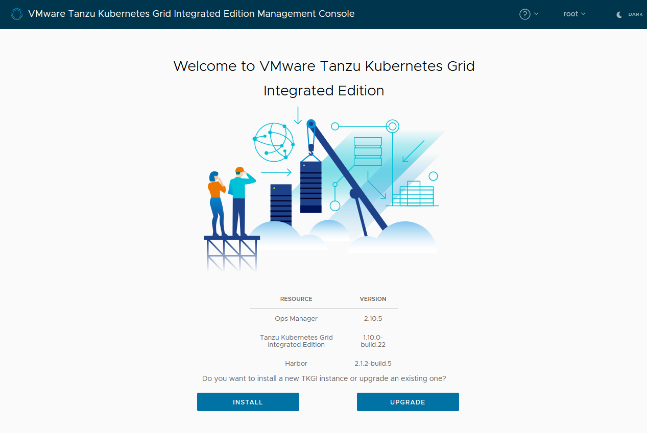
View a larger version of this image - Click Start Configuration.
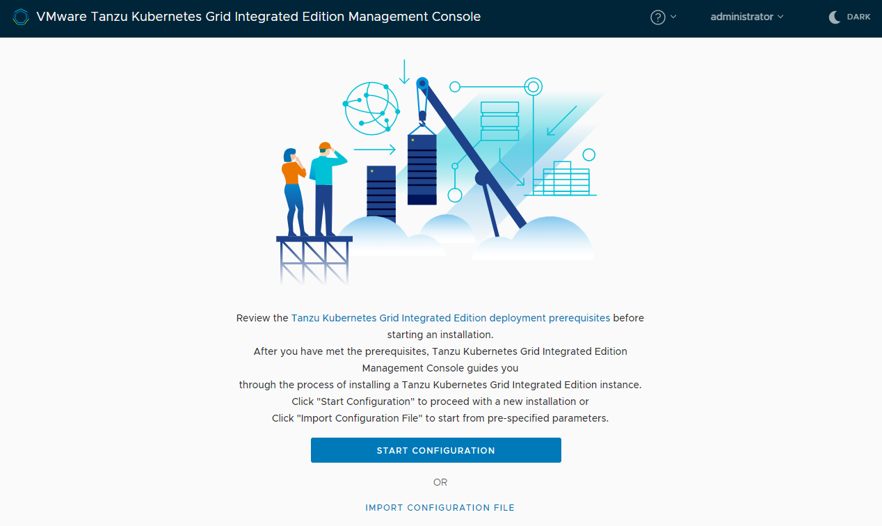
View a larger version of this image
To get help in the wizard at any time, click the ? icon at the top of the page and select Help, or click the More Info… links in each section to see help topics relevant to that section. Click the i icons for tips about how to fill in specific fields.
Step 1: Connect to vCenter Server
To connect to a vCenter Server:
- Enter the IP address or FQDN for the vCenter Server instance on which to deploy Tanzu Kubernetes Grid Integrated Edition.
- The FQDN for the vCenter Server cannot contain uppercase letters.
- Enter the vCenter Single Sign On user name and password for a user account that has vSphere administrator permissions.
- The vCenter user name must have the format
user@domainname, for example: “[email protected]”. It cannot contain a backslash (\) character; TKGI does not support user names of the formatDomain\User.
- The vCenter user name must have the format
- Click Connect.
-
Select the data center in which to deploy Tanzu Kubernetes Grid Integrated Edition from the drop-down menu.
WARNING: Ideally, do not deploy TKGI from the management console to a data center that also includes TKGI instances that you deployed manually. If deploying management console and manual instances of TKGI to the same data center cannot be avoided, make sure that the TKGI instances that you deployed manually do not use the folder names
BoshVMFolder: pks_vms,BoshTemplateFolder: pks_templates,BoshDiskPath: pks_disk. If a manual installation uses these folder names, the VMs that they contain will be deleted when you delete a TKGI instance from the management console. - Click Next to configure networking.
Step 2: Configure Networking
Provide connection information for the container networking interface to use with Tanzu Kubernetes Grid Integrated Edition. Tanzu Kubernetes Grid Integrated Edition Management Console provides 3 network configuration options for your Tanzu Kubernetes Grid Integrated Edition deployments: Automated NAT deployment, Bring your own topology, and Antrea and Flannel.
Each network configuration option has specific prerequisites:
- Automated NAT deployment: Deploy Tanzu Kubernetes Grid Integrated Edition to an existing NSX-T Data Center network that you have not fully set up, that Tanzu Kubernetes Grid Integrated Edition Management Console configures for you. See Configure an Automated NAT Deployment to NSX-T Data Center below for instructions.
- Bring your own topology: Deploy Tanzu Kubernetes Grid Integrated Edition to an existing NSX-T Data Center network that you have fully configured yourself. See Configure a Bring Your Own Topology Deployment to NSX-T Data Center below for instructions.
- Antrea and Flannel: Deploy Tanzu Kubernetes Grid Integrated Edition with either an Antrea or Flannel network that Tanzu Kubernetes Grid Integrated Edition Management Console provisions for you. See Configure an Antrea or Flannel Network below for instructions.
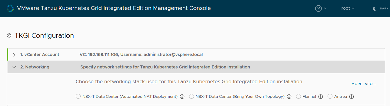
View a larger version of this image.
Important: You cannot change the type of networking after you deploy Tanzu Kubernetes Grid Integrated Edition.
Configure an Automated NAT Deployment to NSX-T Data Center
Provide information about an NSX-T Data Center network that you have not already configured for use with Tanzu Kubernetes Grid Integrated Edition. You provide information about your NSX-T Data Center setup, and Tanzu Kubernetes Grid Integrated Edition Management Console creates the necessary objects and configures them for you. Make sure that your NSX-T Data Center setup satisfies the Prerequisites for an Automated NAT Deployment to NSX-T Data Center before you begin.
To provide information about an NSX-T Data Center network:
- Select the NSX-T Data Center (Automated NAT Deployment) radio button.
- Configure the connection to NSX Manager.
- Enter the IP address or FQDN of NSX Manager.
- Enter the user name and password for an NSX administrator account.
- Click Connect.
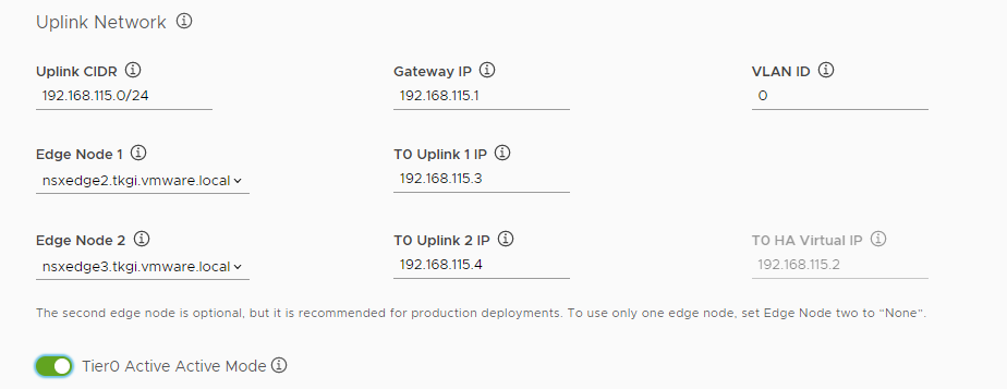
- Enter information about the uplink network.
- Uplink CIDR: Enter a CIDR range within the uplink subnet for the Tier 0 uplinks, for example 10.40.206.0/24.
- Gateway IP: Enter the IP address for the gateway, for example 10.40.206.125.
- VLAN ID: Enter the VLAN ID within the range 0 to 4095, for example 1206.
- Edge Node 1: Select an Edge Node from the drop-down menu, for example
nsx-edge-1. - T0 Uplink 1 IP: Enter the IP address of the Tier 0 uplink 1, for example 10.40.206.9.
- Edge Node 2: Select an Edge Node from the drop-down menu, for example
nsx-edge-2. The second edge node is optional for proof-of-concept deployments, but it is strongly recommended for production deployments. To use only one edge node, set Edge Node two toNone. - T0 Uplink 2 IP: Enter the IP address of the Tier 0 uplink 1, for example 10.40.206.11.
- T0 HA Virtual IP: Enter the IP address for the HA Virtual IP, for example 10.40.206.24.
-
Optionally activate Tier0 Active-Active Mode.
By default, the management console sets the high availability (HA) mode of the tier 0 router to active-standby. You can optionally activate active-active mode on the tier 0 router, so that all NAT configuration moves from the tier 0 to the tier 1 router.
-
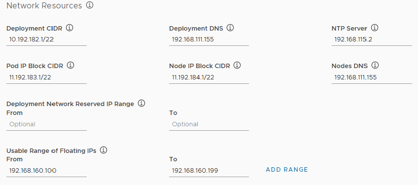
Enter information about the network resources for the Tanzu Kubernetes Grid Integrated Edition deployment to use.
- Deployment CIDR: Enter a CIDR range to use for Tanzu Kubernetes Grid Integrated Edition components, for example 10.192.182.1/22.
- Deployment DNS: Enter the IP address of the DNS server to use for deploying Tanzu Kubernetes Grid Integrated Edition components, for example 192.168.111.155.
- NTP Server: Enter the IP address of an NTP server.
- Pod IP Block CIDR: Enter a CIDR range to use for pods, with a maximum suffix of 24. For example 11.192.183.1/22.
- Node IP Block CIDR: Enter a CIDR range to use for nodes, with a maximum suffix of 22. For example 11.192.184.1/22.
- Nodes DNS: Enter the Domain Name Server used by the Kubernetes nodes.
- Deployment Network Reserved IP Range: Optionally enter a range of IP addresses in the From and To text boxes. No VMs are deployed in this range. You cannot modify reserved IP ranges after the initial deployment. You can specify additional reserved IP ranges by editing the YAML configuration for your deployment before you deploy it in Step 10: Generate Configuration File and Deploy Tanzu Kubernetes Grid Integrated Edition.
- Usable range of floating IPs: Enter the floating IP range, for example From 192.168.160.100 To 192.168.160.199. Click Add Range to add more IP ranges.
-
Optionally activate Manage certificates manually for NSX if NSX Manager uses a custom CA certificate.
Important: If NSX-T Data Center uses custom certificates and you do not provide the CA certificate for NSX Manager, Tanzu Kubernetes Grid Integrated Edition Management Console automatically generates one and registers it with NSX Manager. This can cause other services that are integrated with NSX Manager not to function correctly. If you have manually deployed TKGI instances to the same data center as the one to which you are deploying this instance, you must select Manage certificates manually for NSX and enter the current NSX-T manager CA certificate.
Enter the contents of the CA certificate in the NSX Manager CA Cert text box:
-----BEGIN CERTIFICATE-----
nsx_manager_CA_certificate_contents
-----END CERTIFICATE-----
If you do not select Manage certificates manually for NSX, the management console generates a certificate for you.
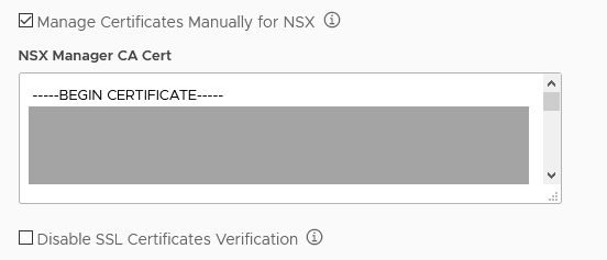
- Optionally activate Disable SSL certificates verification to allow unsecured connections to NSX Manager.
- Click Next to configure identity management.
For the next steps, see Configure Identity Management.
Configure a Bring Your Own Topology Deployment to NSX-T Data Center
Provide information about an NSX-T Data Center network that you have already fully configured for use with Tanzu Kubernetes Grid Integrated Edition. Make sure that your NSX-T Data Center setup satisfies the Prerequisites for a Bring Your Own Topology Deployment to NSX-T Data Center before you begin.
To provide information about an NSX-T Data Center network:
- Select the NSX-T Data Center (Bring Your Own Topology) radio button.
- Configure the connection to NSX Manager.
- Enter the IP address or FQDN of the NSX Manager.
- Enter the user name and password for an NSX administrator account.
- Click Connect.
-
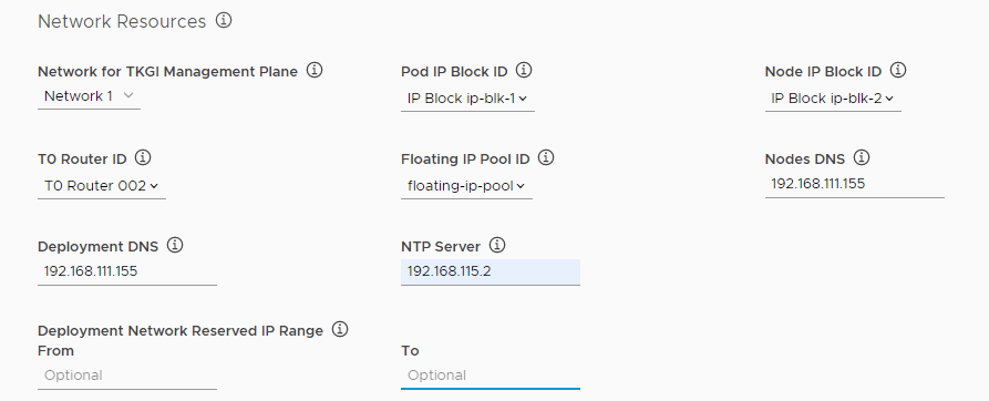
Use the drop-down menus to select existing network resources for each of the following items.
-
Network for TKGI Management Plane: Select the name of an opaque network on an NSX-T Virtual Distributed Switch (N-VDS).
Important: Do not use the network on which you deployed the Tanzu Kubernetes Grid Integrated Edition Management Console VM as the network for the management plane. Using the same network for the management console VM and the management plane requires additional NSX-T Data Center configuration and is not recommended.
- Pod IP Block ID: Select the UUID for the IP block to use for Kubernetes pods.
- Node IP Block ID: Select the UUID for the IP block to use for Kubernetes nodes.
- T0 Router ID: Select the UUID for the Tier-0 Logical Router configured in NSX-T Data Center.
- Floating IP Pool ID: Select the UUID for the Floating IP Pool.
-
-
Enter IP addresses for the following resources.
- Nodes DNS: Enter the IP address for the DNS server to use for Kubernetes nodes and pods.
- Deployment DNS: Enter the IP address for the DNS server to use for the TKGI control plane VMs, for example 192.168.111.155.
- NTP Server: Enter the IP address of an NTP server.
- Deployment Network Reserved IP Range: Optionally enter a range of IP addresses in the From and To text boxes. No VMs are deployed in this range. You cannot modify reserved IP ranges after the initial deployment. You can specify additional reserved IP ranges by editing the YAML configuration for your deployment before you deploy it in Step 10: Generate Configuration File and Deploy Tanzu Kubernetes Grid Integrated Edition.
- If you are using the NSX Policy API, select this option. See Considerations for Using the NSX Policy API with TKGI.
-
Optionally deactivate NAT Mode to implement a routable (No-NAT) topology.
Tanzu Kubernetes Grid Integrated Edition supports NAT topologies, No-NAT with logical switch (NSX-T) topologies, No-NAT with virtual switch (VSS/VDS) topologies, and multiple tier-0 routers for tenant isolation. For information about implementing a routable topology, see No-NAT Topology in NSX-T Deployment Topologies for Tanzu Kubernetes Grid Integrated Edition.
- If you left NAT mode activated, optionally activate Hybrid NAT Mode.
If you activate hybrid NAT mode, the Tanzu Kubernetes Grid Integrated Edition management plane runs on a routable subnet but the cluster node network uses a non-routable subnet. -
Optionally activate Manage certificates manually for NSX if NSX Manager uses a custom CA certificate.
Important: If NSX-T Data Center uses custom certificates and you do not provide the CA certificate for NSX Manager, Tanzu Kubernetes Grid Integrated Edition Management Console automatically generates one and registers it with NSX Manager. This can cause other services that are integrated with NSX Manager not to function correctly. If you have manually deployed TKGI instances to the same data center as the one to which you are deploying this instance, you must select Manage certificates manually for NSX and enter the current NSX-T manager CA certificate.
Enter the contents of the CA certificate in the NSX Manager CA Cert text box:
-----BEGIN CERTIFICATE-----
nsx_manager_CA_certificate_contents
-----END CERTIFICATE-----
If you do not select Manage certificates manually for NSX, the management console generates a certificate for you.
- Optionally activate Disable SSL certificates verification to allow unsecured connections to NSX Manager.
- Click Next to configure identity management.
For the next steps, see Configure Identity Management.
Configure an Antrea or Flannel Network
Provide networking information so that Tanzu Kubernetes Grid Integrated Edition Management Console can provision an Antrea or Flannel network for you during deployment. Make sure that you have the information listed in Prerequisites for vSphere Without an NSX-T Network before you begin.
To provide networking information:
- Select either the Antrea or Flannel radio button.
The options for Antrea and Flannel networking are identical. -
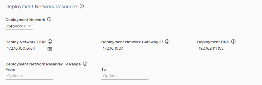
Configure the Deployment Network Resource options.
- Deployment Network: Select a vSphere network on which to deploy Tanzu Kubernetes Grid Integrated Edition.
- Deployment Network CIDR: Enter a CIDR range to use for Tanzu Kubernetes Grid Integrated Edition components, for example 10.192.182.1/22.
- Deployment Network Gateway IP: Enter the IP address for the gateway for the deployment network, for example 10.192.182.1.
- Deployment DNS: Enter the IP address for the deployment network DNS server, for example 192.168.111.155.
- Deployment Network Reserved IP Range: Optionally enter a range of IP addresses in the From and To text boxes. No VMs are deployed in this range. You cannot modify reserved IP ranges after the initial deployment. You can specify additional reserved IP ranges by editing the YAML configuration for your deployment before you deploy it in Step 10: Generate Configuration File and Deploy Tanzu Kubernetes Grid Integrated Edition.
-
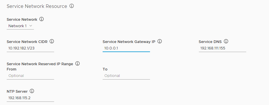
Configure the Service Network Resource options.
- Service Network: Select a vSphere network to use as the service network.
- Service Network CIDR: Enter a CIDR range to use for the service network, for example 10.192.182.1/23.
- Service Network Gateway IP: Enter the IP address for the gateway for the service network.
- Service DNS: Enter the IP address for the service network DNS server, for example 192.168.111.155.
- Service Network Reserved IP Range: Optionally enter a range of IP addresses in the From and To text boxes. No VMs are deployed in this range. You cannot modify the reserved IP range after the initial deployment. You can specify additional reserved IP ranges by editing the YAML configuration for your deployment before you deploy it in Step 10: Generate Configuration File and Deploy Tanzu Kubernetes Grid Integrated Edition.
- NTP Server: Enter the IP address of an NTP server.
-
Configure the Kubernetes network options.
- Pod Network CIDR: Enter a CIDR range to use for pods, for example 11.192.182.1/31.
- Service Network CIDR: Enter a CIDR range to use for the Kubernetes services, for example 10.192.182.1/23.
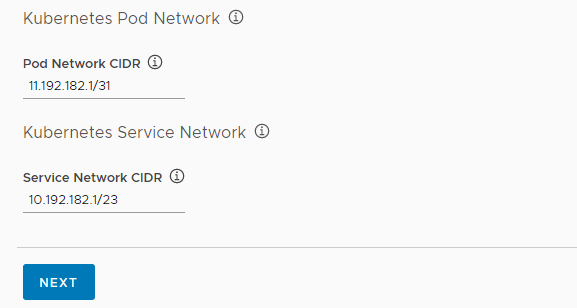
- Click Next to configure identity management.
Step 3: Configure Identity Management
Tanzu Kubernetes Grid Integrated Edition Management Console provides 3 identity management options for your Tanzu Kubernetes Grid Integrated Edition deployments.
To configure identity management:
-
Configure the identity management option for your deployments:
- A local database of users: See Use a Local Database below for instructions.
- Connect to an external Active Directory or LDAP server: See Use an External LDAP Server below for instructions.
- Connect to a SAML identity provider: See Use a SAML Identity Provider below for instructions.
Use a Local Database
You can manage users by using a local database that is created during Tanzu Kubernetes Grid Integrated Edition deployment. After deployment, you can add users and groups to the database and assign roles to them in the Identity Management view of the Tanzu Kubernetes Grid Integrated Edition Management Console.
- Select the Local user database radio button.
- In the TKGI API FQDN text box, enter an address for the TKGI API Server VM, for example
api.tkgi.example.com.Note: The FQDN for the TKGI API cannot contain uppercase letters.
Use an External LDAP Server
Provide information about an existing external Active Directory or LDAP server:
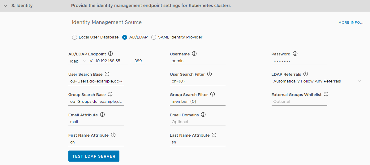
- Select the AD/LDAP radio button.
- For AD/LDAP Endpoint, select ldap or ldaps from the drop-down menu and enter the IP address and port of the AD or LDAP server.
- Enter the user name and password to use to connect to the server.
- Enter the remaining details for your server:
- User Search Base: Enter the location in the AD/LDAP directory tree where user search begins. For example, a domain named
cloud.example.commight useou=Users,dc=example,dc=com. - User Search Filter: Enter a string to use for user search criteria. For example, the standard search filter
cn=Smithreturns all objects with a common name equal toSmith. Usecn={0}to return all LDAP objects with the same common name as the user name. - LDAP Referrals: Select how to handle references to alternate locations in which AD/LDAP requests can be processed:
- Automatically follow referrals
- Ignore referrals
- Abort authentication
- Group Search Base: Optionally enter the location in the AD/LDAP directory tree where group search begins. For example, a domain named
cloud.example.commight useou=Groups,dc=example,dc=com. - Group Search Filter: Enter a string that defines AD/LDAP group search criteria, such as
member={0}. - Group Max Search Depth: Enter the LDAP group search depth, such as
1. Allowed values are between1and10. The default value is1, which limits queering under the searchBase to one subtree. Values greater than1activate nested group searching. If the searchBase in your LDAP groups includes more than one subtree, for example:ou=XX1,ou=XX2,ou=XX3,dc=yy1,dc=yy2,dc=yy3, increase the Group Max Search Depth value to support searching all subtrees in your groups.
Note: Increasing the LDAP group search depth impacts performance.
- External Groups Whitelist: Optionally enter a comma-separated list of group patterns to be populated in the user’s
id_token. - Email Attribute: Enter the attribute name in the AD/LDAP directory that contains user email addresses. For example,
mail. - Email Domains: Optionally enter a comma-separated list of the email domains for external users who can receive invitations to Tanzu Kubernetes Grid Integrated Edition.
- First Name Attribute: Optionally enter the attribute name in the AD/LDAP directory that contains user first names, for example
cn. - Last Name Attribute: Optionally enter the attribute name in the AD/LDAP directory that contains user last names. for example
sn. - Server SSL Certificate: If you are using an LDAPS endpoint, paste the contents of the LDAP server certificate certificate into the text box.
- User Search Base: Enter the location in the AD/LDAP directory tree where user search begins. For example, a domain named
- Optionally click the Test LDAP Server button to test the connection that you have configured.
- In the TKGI API FQDN text box, enter an address for the TKGI API Server VM, for example
api.tkgi.example.com.Note: The FQDN for the TKGI API cannot contain uppercase letters.
Use a SAML Identity Provider
You can configure Tanzu Kubernetes Grid Integrated Edition so that Kubernetes authenticates users against a SAML identity provider. Before you configure a SAML identity provider, you must configure your identity provider to designate Tanzu Kubernetes Grid Integrated Edition as a service provider. For information about how to configure Okta and Azure Active Directory, see the following topics:
- Configuring Okta as a SAML Identity Provider
- Configuring Azure Active Directory as a SAML Identity Provider
After you have configured your identity provider, enter information about the provider in Tanzu Kubernetes Grid Integrated Edition Management Console:
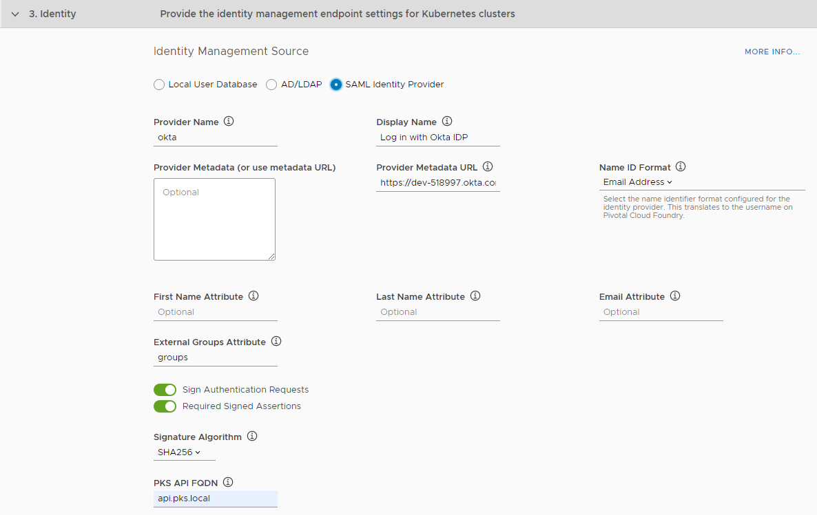
- Select the SAML Identity Provider radio button.
-
For Provider Name, enter a unique name you create for the Identity Provider.
This name can include only alphanumeric characters,+,_, and-. You must not change this name after deployment because all external users use it to link to the provider. -
For Display Name, enter a display name for your provider.
The display name appears as a link on your login page. -
Enter the metadata from your identity provider either as XML or as a URL.
- Download your identity provider metadata and paste the XML into Provider Metadata.
- If your identity provider exposes a metadata URL, enter it in Provider Metadata URL.
-
For Name ID Format, select the name identifier format for your SAML identity provider.
This translates tousernameon TKGI. The default isEmail Address. -
For First Name Attribute and Last Name Attribute, enter the attribute names in your SAML database that correspond to the first and last names in each user record.
These fields are case sensitive. -
For Email Attribute, enter the attribute name in your SAML assertion that corresponds to the email address in each user record, for example,
EmailID.
This field is case sensitive. -
For External Groups Attribute, enter the attribute name in your SAML database for your user groups.
This field is case sensitive. To map the groups from the SAML assertion to admin roles in Tanzu Kubernetes Grid Integrated Edition, see Grant Tanzu Kubernetes Grid Integrated Edition Access to an External LDAP Group. -
By default, all SAML authentication requests from Tanzu Kubernetes Grid Integrated Edition are signed, but you can optionally deactivate Sign Authentication Requests.
If you deactivate this option, you must configure your identity provider to verify SAML authentication requests. -
To validate the signature for the incoming SAML assertions, activate Required Signed Assertions.
If you activate this option, you must configure your Identity Provider to send signed SAML assertions. -
For Signature Algorithm, choose an algorithm from the drop down to use for signed requests and assertions.
The default value is SHA256. -
In the TKGI API FQDN text box, enter an address for the TKGI API Server VM, for example
api.tkgi.example.com.Note: The FQDN for the TKGI API cannot contain uppercase letters.
(Optional) Configure UAA and Custom Certificates
However you manage identities, you can use OpenID Connect (OIDC) to instruct Kubernetes to verify end-user identities based on authentication performed by a User Account and Authentication (UAA) server. Using OIDC lets you set up an external IDP, such as Okta, to authenticate users who access Kubernetes clusters with kubectl. If you activate OIDC, administrators can grant namespace-level or cluster-wide access to Kubernetes end users. If you do not activate OIDC, you must use service accounts to authenticate kubectl users.
Note: You cannot activate OIDC if you intend to integrate Tanzu Kubernetes Grid Integrated Edition with VMware vRealize Operations Management Pack for Container Monitoring.
To configure UAA to verify and authenticate end-user identities:
-
(Optional) Select Configure created clusters to use UAA as the OIDC provider and provide the following information.
- UAA OIDC Groups Claim: Sets the
--oidc-groups-claimflag on the kube-api server. Enter the name of your groups claim. This is used to set a user’s group in the JSON Web Token (JWT) claim. The default value isroles. - UAA OIDC Groups Prefix: Sets the
--oidc-groups-prefixflag. Enter a prefix for your groups claim. This prevents conflicts with existing names. For example, if you enter the prefixoidc:, UAA creates a group name likeoidc:developers. - UAA OIDC Username Claim: Sets the
--oidc-username-claimflag. Enter the name of your user name claim. This is used to set a user’s user name in the JWT claim. The default value isuser_name. Depending on your provider, admins can enter claims besidesuser_name, such asemailorname. - UAA OIDC Username Prefix: Sets the
--oidc-username-prefixflag. Enter a prefix for your user name claim. This prevents conflicts with existing names. For example, if you enter the prefixoidc:, UAA creates a user name likeoidc:admin.
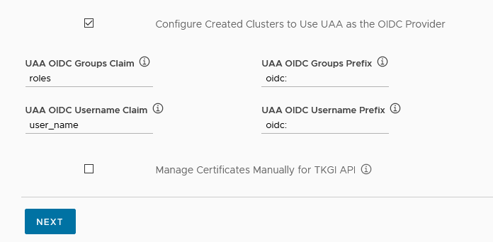
- UAA OIDC Groups Claim: Sets the
-
(Optional) Select Manage Certificates Manually for TKGI API to generate and upload your own certificates for the TKGI API Server.
If you do not select this option, the management console creates auto-generated, self-signed certificates.
Enter the contents of the certificate in the TKGI API Certificate text box:-----BEGIN CERTIFICATE----- tkgi_api_certificate_contents -----END CERTIFICATE-----Enter the contents of the certificate key in the Private Key PEM text box:
-----BEGIN RSA PRIVATE KEY----- tkgi_api_private_key_contents -----END RSA PRIVATE KEY----- - Click Next to configure availability zones.
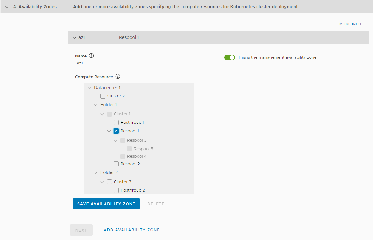
Step 4: Configure Availability Zones
Availability zones specify the compute resources for Kubernetes cluster deployment. Availability zones are a BOSH construct, that in Tanzu Kubernetes Grid Integrated Edition deployments to vSphere correspond to vCenter Server clusters, host groups, and resource pools. Availability zones allow you to provide high-availability and load balancing to applications. When you run more than one instance of an application, those instances are balanced across all of the availability zones that are assigned to the application. You must configure at least one availability zone. You can configure multiple additional availability zones.
Note: If you select a cluster as an availability zone, Tanzu Kubernetes Grid Integrated Edition Management Console sets the DRS VM-host affinity rule on that cluster to MUST. If you select a host group as an availability zone, Tanzu Kubernetes Grid Integrated Edition Management Console sets the DRS VM-host affinity rule on that group to SHOULD.
To configure availability zones:
- In the Name field, enter a name for the availability zone.
-
Optionally select This is the management availability zone.
The management availability zone is the availability zone in which to deploy the TKGI Management Plane. The management plane consists of the TKGI API VM, Ops Manager, BOSH Director, and Harbor Registry. You can only designate one availability zone as the management zone. If you do not designate an availability zone as the management zone, Tanzu Kubernetes Grid Integrated Edition Management Console selects the first one.
- In the Compute Resource tree, select clusters, host groups, or resource pools for this availability zone to use.
-
Click Save Availability Zone.
-
Optionally click Add Availability Zone to add another zone.
You can only select resources that are not already included in another zone. You can create multiple availability zones.
- Click Save Availability Zone for every additional availability zone that you create.
- Click Next to configure storage.
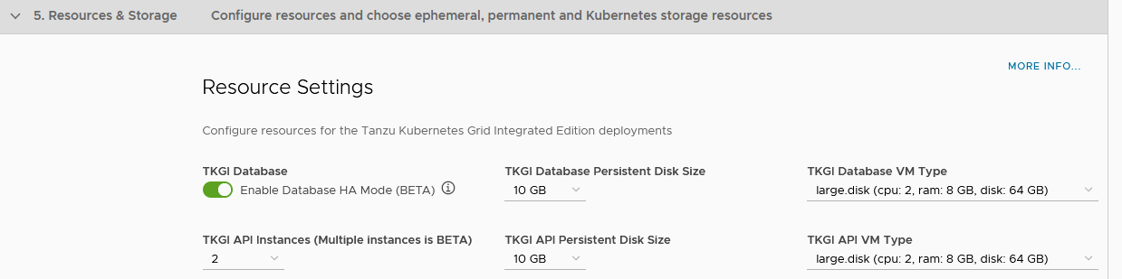
Step 5: Configure Resources and Storage
Resource Settings allow you to configure the resources that are allocated to the VM on which the Tanzu Kubernetes Grid Integrated Edition API and other component services, such as UAA, run. Allocate resources according to the workloads that TKGI will run. You can also activate High Availability for the TKGI Database and deploy multiple instances of the TKGI API VM.
Tanzu Kubernetes Grid Integrated Edition, the MySQL database runs on a separate VM to the Tanzu Kubernetes Grid Integrated Edition API and other components.
You must also designate the datastores to use for the different types of storage required by your Tanzu Kubernetes Grid Integrated Edition deployment.
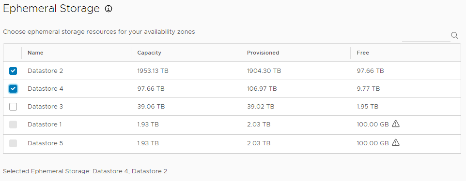
- Ephemeral storage is used to contain the files for ephemeral VMs that Tanzu Kubernetes Grid Integrated Edition creates during installation, upgrade, and operation. Ephemeral VMs are automatically created and deleted as needed.
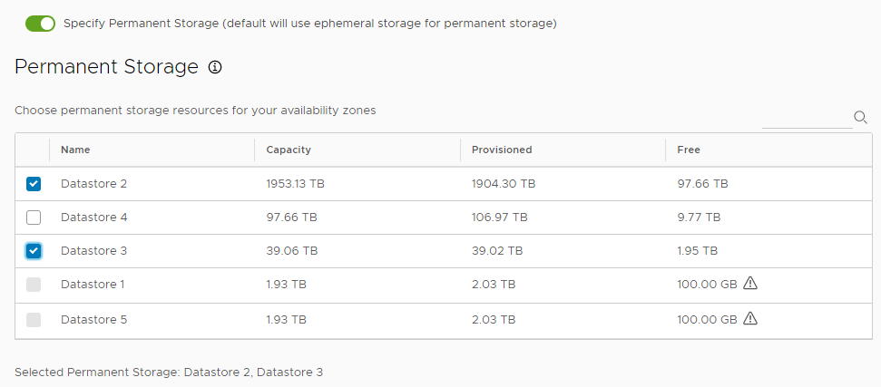
- Permanent storage is used for permanent Tanzu Kubernetes Grid Integrated Edition data.
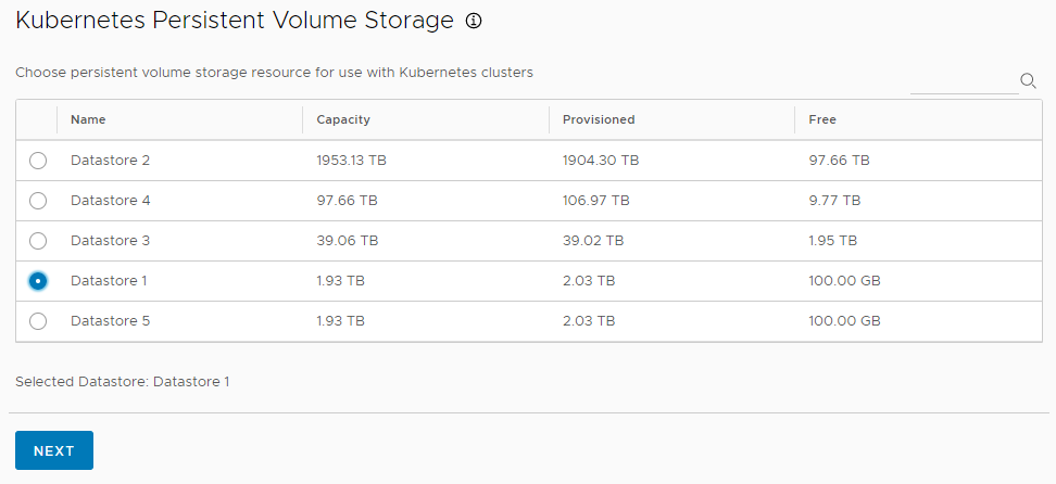
- Kubernetes persistent volume storage is used to store Kubernetes persistent volumes, for use in stateful applications.
You can use different datastores for the storage of permanent and ephemeral data. If you deactivate the permanent storage option, Tanzu Kubernetes Grid Integrated Edition uses the ephemeral storage for permanent data. For information about when it is appropriate to share the ephemeral, permanent, and persistent volume datastores or use separate ones, see PersistentVolume Storage Options on vSphere.
You can use VMware vSAN, Network File Share (NFS), or VMFS storage for ephemeral, permanent, and Kubernetes persistent storage. Datastores can only be selected if their minimum capacity is greater than 250GB.
To configure the resources available on the Tanzu Kubernetes Grid Integrated Edition API VM:
- (Optional) Toggle TKGI Database to activate database HA mode.
-
For TKGI Database Persistent Disk Size, select the size of the persistent disk for the Tanzu Kubernetes Grid Integrated Edition MySQL database VM.
- Set the TKGI Database Persistent Disk Size according to the amount of data that you expect the cluster workload to store.
-
Use the TKGI Database VM Type drop-down menu to select from different combinations of CPU, RAM, and storage for the Tanzu Kubernetes Grid Integrated Edition MySQL database VM.
- Choose the configuration for the TKGI Database VM depending on the volume of database operations that it will run.
- Use the TKGI API Instances drop-down menu to select 1, 2, or 3 instances of the TKGI API VM.
-
For TKGI API Persistent Disk Size, select the size of the persistent disk for the Tanzu Kubernetes Grid Integrated Edition API VM.
Set the TKGI API Persistent Disk Size according to the number of pods that you expect the cluster workload to run continuously. It is recommended to allocate 10GB for every 500 pods. For example:
- For 1000 pods, allocate
20GB. - For 10,000 pods, allocate
200GB. - For 50,000 pods, allocate
1TB.
- For 1000 pods, allocate
-
Use the TKGI API VM Type drop-down menu to select from different combinations of CPU, RAM, and storage for the Tanzu Kubernetes Grid Integrated Edition API VM.
Choose the configuration for the API VM depending on the expected CPU, memory, and storage consumption of the workloads that it will run. For example, some workloads might require a large compute capacity but relatively little storage, while others might require a large amount of storage and less compute capacity.
- Under Ephemeral Storage, select one or more datastores for use as ephemeral storage, or use the search field on the right to find datastores by name.
- (Optional) Activate Specify Permanent Storage to designate different datastores for ephemeral and permanent data.
- If you activated permanent storage, under Permanent Storage, select one or more datastores for permanent storage, or use the search field to find datastores by name.
- Under Kubernetes Persistent Volume Storage, select one datastore in which to store Kubernetes volumes, or use the search field to find datastores by name.
- Click Next to configure plans.
Step 6: Configure Plans
A plan is a cluster configuration template that defines the set of resources for Tanzu Kubernetes Grid Integrated Edition to use when deploying Kubernetes clusters. A plan allows you to configure the numbers of control plane and worker nodes, select between Linux and Windows OS for worker nodes, specify the configuration of the control plane and worker VMs, set disk sizes, select availability zones for control plane and node VMs, and configure advanced settings.
Tanzu Kubernetes Grid Integrated Edition Management Console provides preconfigured default plans, for different sizes of Kubernetes clusters. You can change the default configurations, or you can activate the plans as they are. You must activate at least one plan configuration because when you use the TKGI CLI to create a Kubernetes cluster, you must specify the plan on which you are basing the Kubernetes cluster. If no plans are activated, you cannot create Kubernetes clusters.
Tanzu Kubernetes Grid Integrated Edition plans support privileged containers and three admission control plugins. For information about privileged containers and the supported admission plugins, see Privileged mode for pods in the Kubernetes documentation. For information about admission plugins, see Using Admission Control Plugins for Tanzu Kubernetes Grid Integrated Edition Clusters.
You can create a maximum of 10 Linux plans and a maximum of 3 Windows plans.
After you have deployed Tanzu Kubernetes Grid Integrated Edition, when you use the management console to create clusters, you can override some of the values that you define in plans by using Compute Profiles.
To configure a plan:
- If you are configuring a plan for a Windows worker node, see Notes about Windows Worker Nodes below.
- To use the preconfigured plans as they are, click Save Plan for each of the
small,medium, andlargeplans. -
(Optional) Use the drop-down menus and buttons to change the default configurations of the preconfigured plans.
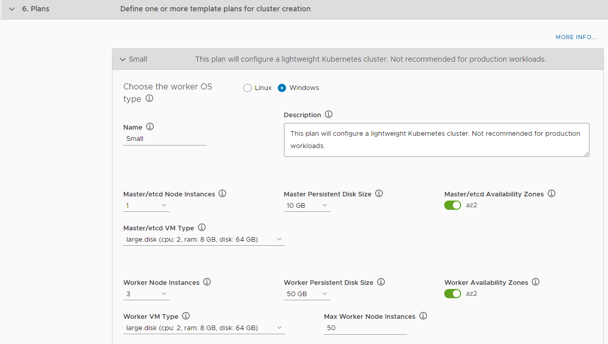
- Select Linux or Windows to set the OS for the worker nodes.
- Enter a name and a description for the plan in the Name and Description text boxes.
- Master/etcd Node Instances: Select 1 (small), 3 (medium), or 5 (large).
- Master Persistent Disk Size: Select the size of the control plane persistent disk.
- Master/etcd Availability Zones: Activate one or more availability zones for the control plane nodes.
- Master/etcd VM Type: Select the size of the Control Plane VM. If you use Windows worker nodes, this option defaults to large.disk.
- Worker Node Instances: Specify the number of worker nodes. For a small deployment, 3 is suggested.
- Worker Persistent Disk Size: Select the size of the worker node persistent disk.
- Worker Availability Zones: Activate one or more available availability zones for the worker nodes.
- Worker VM Type: Select a configuration for worker nodes. If you use Windows worker nodes, this option defaults to large.disk.
- Max Worker Node Instances: Select the maximum number of worker nodes.
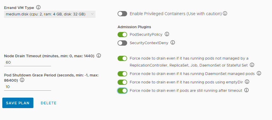
- Errand VM Type: Select the size of the VM to run BOSH errand tasks.
- Enable Privileged Containers: Optionally activate privileged container mode. Use with caution. If you use Windows worker nodes, this option is not available.
- Admission Plugins: Optionally activate the
SecurityContextDenyadmission plugin. Use Admission plugins with caution because they provide a higher level of access control to the Kubernetes API server.Note: The SecurityContextDeny admission controller has been deprecated, and the Kubernetes community recommends the controller not be used. TKGI support for SecurityContextDeny will be removed in TKGI v1.18. Pod security admission (PSA) is the preferred method for providing a more secure Kubernetes environment. For more information about PSA, see Pod Security Admission in TKGI.
- Node Drain Timeout: Enter the timeout in minutes for the node to drain pods. If you set this value to 0, the node drain does not terminate. If you use Windows worker nodes, the node drain options are not available. To configure when the nodes drain, optionally activate the following:
- Force node to drain even if it has running pods not managed by a ReplicationController, ReplicaSet, Job, DaemonSet or Stateful Set
- Force node to drain even if it has running DaemonSet managed pods
- Force node to drain even if it has running pods using emptyDir
- Force node to drain even if pods are still running after timeout
- Pod Shutdown Grace Period: Enter a timeout in seconds for the node to wait before it forces the pod to terminate. If you set this value to -1, the default timeout is set to the one specified by the pod. If you use Windows worker nodes, this option is not available.
-
If you use Windows worker nodes, optionally activate the Enable HA Linux Workers option to deploy two Linux worker nodes per Windows cluster instead of one.
The Linux nodes provide cluster services to the Windows clusters.

- Click Save Plan for each plan that you edit.
- (Optional) To create a new plan, click Add Plan, configure it as described above, and click Save Plan.
- (Optional) Delete any plans that you do not need.
- Click Next to configure integrations.
Notes about Windows Worker Nodes
Consider the following when configuring plans for Windows worker nodes:
- You can use Windows worker nodes if you implement either vSphere with NSX-T or vSphere without NSX-T Data Center networking.
- You can create a maximum of 3 plans that implement Windows worker nodes in a given Tanzu Kubernetes Grid Integrated Edition deployment.
- If you use Windows worker nodes, certain options are not available, and the default values of other options change. See the option descriptions below for more information.
- If you use Windows worker nodes, by default one Linux worker node is deployed per Windows cluster. The Linux node provides cluster services to the Windows worker nodes. You can optionally make the cluster services Linux node highly available, in which case two Linux nodes are deployed.
- If you use Windows worker nodes, after you deploy Tanzu Kubernetes Grid Integrated Edition, you must use Operations Manager to manually install a Windows Server Stemcell in BOSH. For information about how to install a Windows Server Stemcell and other steps to perform after you deploy Tanzu Kubernetes Grid Integrated Edition with Windows worker nodes, see Enable Plans with Windows Worker Nodes.
Step 7: Configure Integrations
If your infrastructure includes existing deployments of VMware Tanzu Mission Control, Wavefront by VMware, VMware vRealize Operations Management Pack for Container Monitoring, or VMware vRealize Log Insight, you can configure TKGI to connect to those services. You can also configure TKGI to forward logs to a Syslog server.
To configure TKGI integration with other products:
- Configure a Connection to VMware Tanzu Mission Control
- Configure a Connection to Wavefront
- Configure a Connection to VMware vRealize Operations Management Pack for Container Monitoring
- Configure a Connection to VMware vRealize Log Insight
- Configure a Connection to Syslog
Configure a Connection to VMware Tanzu Mission Control
Tanzu Mission Control integration lets you monitor and manage Tanzu Kubernetes Grid Integrated Edition clusters from the Tanzu Mission Control console, making the Tanzu Mission Control console a single point of control for all Kubernetes clusters.
For more information about Tanzu Mission Control, see the VMware Tanzu Mission Control home page.
- Select the Enable toggle to activate the Tanzu Mission Control Integration.
- For API URL, enter the API URL of your Tanzu Mission Control subscription, without a trailing slash (
/). - For Cluster Group Name, enter the name of a Tanzu Mission Control cluster group.
- The name can be
defaultor another value, depending on your role and access policy:Org Memberusers in VMware cloud services have aservice.adminrole in Tanzu Mission Control. These users:- By default, can only create and attach clusters in the
defaultcluster group. - Can create new cluster groups after an
organization.adminuser grants them theclustergroup.adminorclustergroup.editrole.
- By default, can only create and attach clusters in the
- VMware cloud services
Org Ownerusers haveorganization.adminpermissions in Tanzu Mission Control. These users:- Can create cluster groups.
- Can grant
clustergrouproles toservice.adminusers through the Tanzu Mission Control Access Policy view.
- Tanzu Mission Control Cluster Name Prefix: Enter a name prefix for identifying the TKGI clusters in Tanzu Mission Control.
- The name can be
- For API token, Enter your API token to authenticate with VMware Cloud Services APIs. Retrieve this token by logging into VMware Cloud Services and viewing your account information.
-
For Cluster Name Prefix, enter a name prefix for identifying the TKGI clusters in Tanzu Mission Control. This name prefix cannot contain uppercase letters. For more information, see the see Cluster Group Name Limitation for Tanzu Mission Control Integration in the Release Notes.
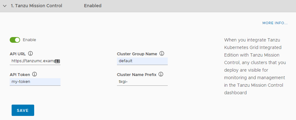
- Click Save.
- Configure integrations with other applications, or click Next to install Harbor.
Configure a Connection to Wavefront
By connecting your Tanzu Kubernetes Grid Integrated Edition deployment to an existing deployment of Wavefront by VMware, you can obtain detailed metrics about Kubernetes clusters and pods.
To configure Wavefront integration:
- Ensure you have an active Wavefront account and access to a Wavefront instance.
To configure Wavefront integration, you must have an active Wavefront account and access to a Wavefront instance. For more information, including about how to generate a Wavefront access token, see VMware TKGI Integration and VMware TKGI Integration Details in the Wavefront by VMware documentation. - Select the Enable toggle to activate a connection to Wavefront.
- Enter the address of your Wavefront instance in the Wavefront URL text box.
- Enter the Wavefront API token in the Wavefront Access Token text box.
- In the HTTP Proxy for TKGI text box, enter the address of the proxy server to use when it is not possible for the Tanzu Kubernetes Grid Integrated Edition Wavefront component to connect to an outside address over HTTP. For example, http://your.proxy.com:8080 or https://your.proxy.com:443.
- Click Save.
- Configure integrations with other applications, or click Next to install Harbor.
Configure a Connection to VMware vRealize Operations Management Pack for Container Monitoring
vRealize Operations Management Pack for Container Monitoring provides detailed monitoring of your Kubernetes clusters. You can connect your TKGI deployment to an existing instance of VMware vRealize Operations Management Pack for Container Monitoring.
To connect a TKGI deployment to VMware vRealize Operations Management Pack for Container Monitoring:
- Ensure vRealize Operations Management Pack for Container Monitoring is available in your environment. vRealize Operations Management Pack for Container Monitoring must be installed, licensed, running, and available before activating integration with a TKGI deployment.
To install vRealize Operations Management Pack for Container Monitoring, see the vRealize Operations Management Pack for Container Monitoring Documentation. - Select the Enable toggle to activate a connection to vRealize Operations Management Pack for Container Monitoring.
- Click Save.
- Configure integrations with other applications, or click Next to install Harbor.
TKGI MC automatically creates a cAdvisor container in the TKGI deployment after TKGI integration with VMware vRealize Operations Management Pack for Container Monitoring has been activated.
Configure a Connection to VMware vRealize Log Insight
You can configure TKGI deployment so that an existing deployment of VMware vRealize Log Insight pulls logs from all BOSH jobs and containers running in the cluster, including node logs from core Kubernetes and BOSH processes, Kubernetes event logs, and POD stdout and stderr.
To connect a TKGI deployment to VMware vRealize Log Insight:
- Ensure vRealize Log Insight is available in your environment. vRealize Log Insight must be installed, licensed, running, and available in your environment before you activating integration with a TKGI deployment.
To install and configure vRealize Log Insight, see the vRealize Log Insight documentation. - Select the Enable toggle to activate a connection to vRealize Log Insight.
- Enter the address of your vRealize Log Insight instance in the Host text box.
- Optionally deactivate Enable SSL.
-
Optionally deactivate Disable SSL certificate validation.
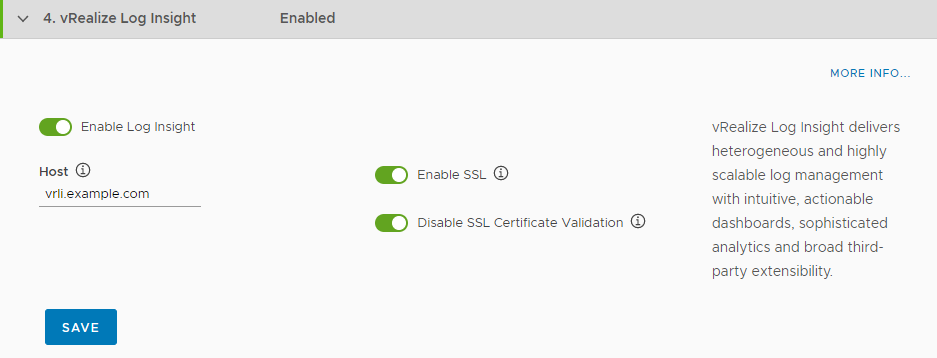
- Click Save.
- Configure integrations with other applications, or click Next to install Harbor.
Note: If you activate integration with vRealize Log Insight, Tanzu Kubernetes Grid Integrated Edition Management Console generates a unique vRealize Log Insight agent ID for the management console. You must provide this agent ID to vRealize Log Insight so that it can pull the appropriate logs from the management console VM. For information about how to obtain the agent ID, see Obtain the VMware vRealize Log Insight Agent ID for TKGI Management Console in Troubleshooting Tanzu Kubernetes Grid Integrated Edition Management Console.
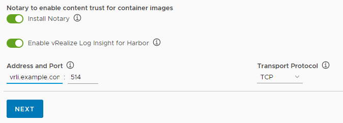
Configure a Connection to Syslog
You can configure your TKGI deployment so that it sends logs for BOSH-deployed VMs, Kubernetes clusters, and namespaces to an existing Syslog server.
To connect your TKGI deployment with an existing Syslog server:
- Select the Enable toggle to activate a connection to Syslog.
- Enter the address of your Syslog server in the Address and port text boxes.
- Select TCP, UDP, or RELP from the Transport protocol drop-down menu.
- Optionally select Enable TLS.
-
Enter a permitted peer ID.
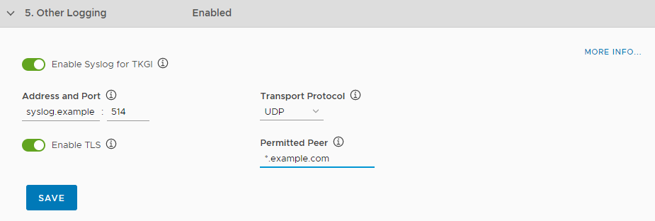
- Click Save.
- Click Next to install Harbor.
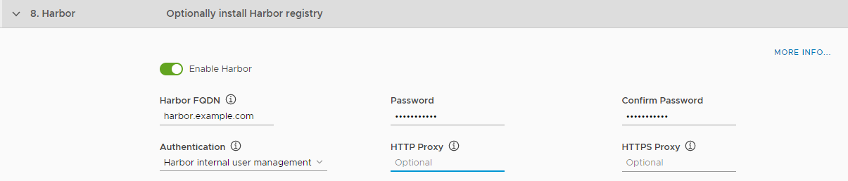
Step 8: (Optional) Configure Harbor
Harbor is an enterprise-class registry server that you can use to store and distribute container images. Harbor allows you to organize image repositories in projects, and to set up role-based access control to those projects to define which users can access which repositories. Harbor also provides rule-based replication of images between registries, optionally implements Content Trust with Notary and vulnerability scanning of stored images with Clair, and provides detailed logging for project and user auditing.
Harbor provides a Notary server that allows you to implement Content Trust by signing and verifying the images in the registry. When Notary content trust is activated, users can only push and pull images that have been signed and verified to or from the registry.
Harbor uses Clair to perform vulnerability and security scanning of images in the registry. You can set thresholds that prevent users from running images that exceed those vulnerability thresholds. Once an image is uploaded into the registry, Harbor uses Clair to check the various layers of the image against known vulnerability databases and reports any issues found.
To deploy and configure Harbor registry:
- Select the Enable toggle to deploy Harbor when you deploy Tanzu Kubernetes Grid Integrated Edition.
-
In the Harbor FQDN text box, enter a name for the Harbor VM, for example
harbor.tkgi.example.com.This is the address at which you access the Harbor administration UI and registry service. Before you set the host name, you must check for potential host name conflicts between TKGI and Harbor. - If the host name might resolve to an IP address that is not one that you want it to, clear the DNS entry manually to avoid conflicts in subsequent use. - If the host name can be resolved to an IP address that you have intentionally created beforehand, be aware that the IP address in the DNS entry might not be the same as the reachable IP address that TKGI Management Console uses, resulting in network issues. If you must use a pre-created DNS entry, after the TKGI deployment finishes, check the IP address that TKGI Management Console uses for Harbor and update the DNS entry accordingly.
-
Enter and confirm a password for the Harbor VM.
- Select the method to use for authenticating connections to Harbor.
- Harbor internal user management: Create a local database of users in the Harbor VM.
- Log in Harbor with LDAP users: Use AD or LDAP to manage users. You configure the connection to the LDAP server in Harbor after deployment.
- UAA in Pivotal Container Service: Use the same UAA as you use for Tanzu Kubernetes Grid Integrated Edition.
-
If your environment does not allow Harbor components to access the external network on which Tanzu Kubernetes Grid Integrated Edition Management Console is running, provide proxy addresses.
- In the HTTP Proxy field, enter the proxy server to use when it is not possible for Harbor to connect to an outside address over HTTP. For example, http://your.proxy.com:8080 or https://your.proxy.com:443.
- In the HTTPS Proxy field, enter the proxy server to use when it is not possible for Harbor to connect to an outside address over HTTPS. For example, http://your.proxy.com:8080 or https://your.proxy.com:443.
These proxies allow Clair to obtain updates from its vulnerability database.
-
(Optional) Select Manage Certificates Manually for Harbor to use custom certificates with Harbor.
To use custom certificates with Harbor:
-
Paste the contents of the server certificate PEM file in the SSL Certificate PEM text box:
-----BEGIN CERTIFICATE----- ssl_certificate_contents -----END CERTIFICATE----- -
Paste the contents of the certificate key in the SSL Key PEM text box:
-----BEGIN PRIVATE KEY----- ssl_private_key_contents -----END PRIVATE KEY----- -
Paste the contents of the Certificate Authority (CA) file in the Certificate Authority text box:
-----BEGIN CERTIFICATE----- CA_certificate_contents -----END CERTIFICATE----- -
Apply the configuration to update the TKGI Management Console database with the revised Harbor certificates.
Note: If you use the TKGI Management Console and Harbor and rotate Harbor certificates within the Harbor tile, you must activate the Manage Certificates Manually For Harbor option and configure the new Harbor certificates.
-
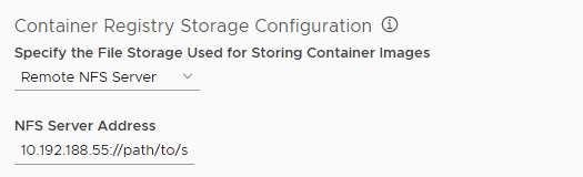
-
Select the location in which to store image repositories.
- Local file system: Stores images in the Harbor VM. No configuration required.
- Remote NFS server: Provide the IP address and path to an NFS share point.
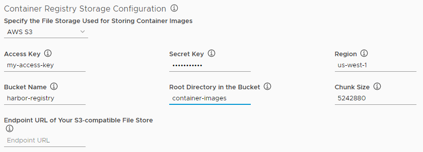
- AWS S3: Provide the connection details for your Amazon S3 account.
- Access Key: Enter your access key ID.
- Secret Key: Enter the secret access key for your access key ID.
- Region: The region in which your bucket is located.
- Bucket Name: Enter the name of your S3 bucket.
- Root Directory in the Bucket: Enter the root directory of the bucket.
- Chunk Size: The default is 5242880 but you can change it if necessary.
- Endpoint URL of your S3-compatible file store: Enter the URL of your S3-compatible filestore.
- Enable v4auth: Access to the S3 bucket is authenticated by default. Deselect this check box for anonymous access.
- Secure mode: Access to your S3 bucket is secure by default. Deselect this check box to deactivate secure mode.
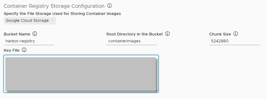
- Google Cloud Storage: Provide the connection details for your Google Cloud Storage account.
- Bucket Name: Enter the name of the GCS bucket.
- Root Directory in the Bucket: Enter the root directory of the bucket.
- Chunk Size: The default is 5242880 but you can change it if necessary.
- Key File: Enter the service account key for your bucket.
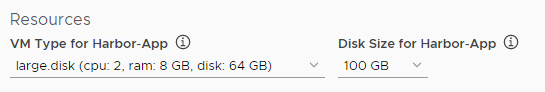
- Select the configuration for the Harbor VM from the VM Type for Harbor-App drop-down menu.
-
Select the size of the disk for the Harbor VM from the Disk Size for Harbor-App drop-down menu.
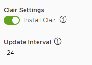
- (Optional) Activate Clair by enabling the Install Clair toggle.
-
In the Update Interval field, specify when Clair will update its CVE databases for the registered sources.
When the updater interval expires, Clair will update its CVE databases. The default updater interval is 0, which means Clair will never update its CVE databases. If you set the updater interval to 24, Clair updates its CVE databases every 24 hours.
- (Optional) Activate Notary by enabling the Install Notary toggle.
-
(Optional) To send Harbor logs to vRealize Log Insight, enable the Enable vRealize Log Insight for Harbor toggle.
If you activate vRealize Log Insight, provide the address and port of your vRealize Log Insight service, and select either UDP or TCP for the transport protocol.
- Click Next to complete the configuration wizard.
Step 9: Configure CEIP
VMware’s Customer Experience Improvement Program (CEIP) provides VMware with information to improve the products and services, fix problems, and advise you on how best to deploy and use our products. As part of the CEIP program, VMware collects technical information about your organization’s use of Tanzu Kubernetes Grid Integrated Edition Management Console.
To configure VMware’s Customer Experience Improvement Program (CEIP), do the following:
- Click CEIP.
- Review the information about the CEIP.
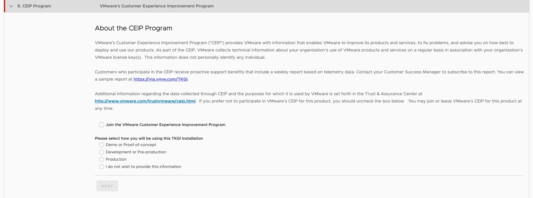
View a larger version of this image. - If you wish to participate in CEIP,select the Join the VMware Customer Experience Improvement Program check box.
- Enter the following information in the fields:
- Your entitlement account number or Tanzu customer number. If you are a VMware customer, you can find your entitlement account number in your Account Summary on my.vmware.com. If you are a Pivotal customer, you can find your Pivotal Customer Number in your Pivotal Order Confirmation email.
- A descriptive name for your TKGI installation. The label you assign to this installation will be used in the reports to identify the environment.
- To provide information about the purpose for this installation, select an option.

- Click Save.
Note: If you join the CEIP Program for Tanzu Kubernetes Grid Integrated Edition, open your firewall to allow outgoing access to https://vcsa.vmware.com/ph on port 443.
Note: Even if you do not wish to participate in CIEP, Tanzu Kubernetes Grid Integrated Edition-provisioned clusters send usage data to the TKGI control plane. However, this data is not sent to VMware and remains on your Tanzu Kubernetes Grid Integrated Edition installation.
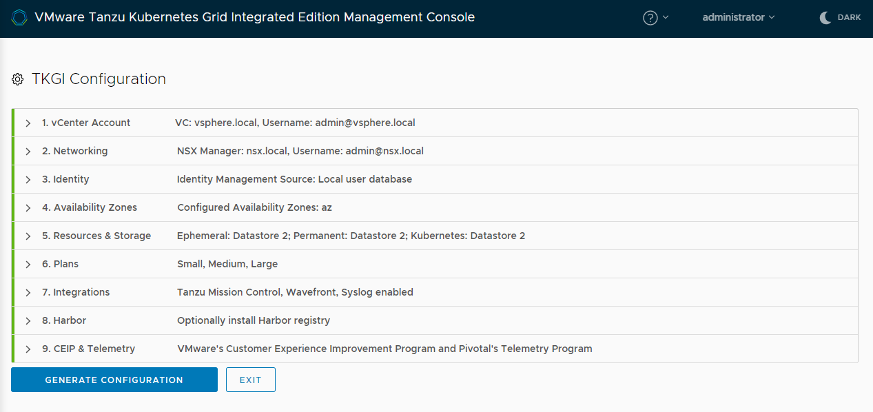
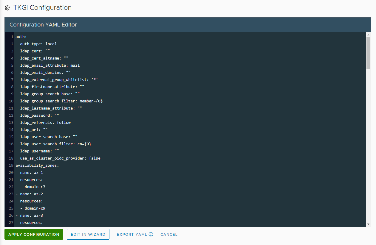
Step 10: Generate Configuration File and Deploy Tanzu Kubernetes Grid Integrated Edition
When all of the sections of the wizard are green, you can generate a YAML configuration file and deploy TKGI.
Note: If TKGI MC fails to deploy TKGI correctly, always use TKGI MC to cleanly remove the failed deployment. For more information see Delete Your Tanzu Kubernetes Grid Integrated Edition Deployment.
To deploy TKGI:
-
Click Generate Configuration to see the generated YAML file.
-
(Optional) Click Export YAML to save a copy of the YAML file for future use.
This is recommended. The manifest is exported as the filePksConfiguration.yaml. -
(Optional) Specify an FQDN address for the Ops Manager VM by editing the YAML directly in the YAML editor.
WARNING: You cannot change the Ops Manager FQDN of Tanzu Kubernetes Grid Integrated Edition once it has already deployed.
To specify an FQDN address for the Ops Manager VM, update the YAML as follows:- Locate the
opsman_fqdn:entry in the YAML file. - Update the
opsman_fqdn:entry with the Ops Manager VM FQDN:opsman_fqdn: "myopsman.example.com". - Make sure that the FQDN is mapped to the following IP address:
- For vSphere with NSX-T deployments map it to the first address in the floating IP range.
- For vSphere without NSX-T deployments, map it to the first address in the deployment network, excluding the gateway, deployment DNS, and reserved IP range.
If you start the deployment and you have not mapped the FQDN to an IP address, the deployment fails with an error. If this happens, configure the mapping as above, return to the YAML editor, and start the deployment again.
- Locate the
-
(Optional) To use a custom certificate for Ops Manager, edit the YAML directly in the YAML editor.
-
Generate a private key and root certificate for Ops Manager, by using
openssl. For example:openssl genrsa -out opsman.key 2048openssl req -key opsman.key -new -x509 -days 365 -sha256 -extensions v3_ca -out opsman_ca.crt -subj "/C=US/ST=CA/L=Palo Alto/O=Vmware/OU=Eng/CN=Sign By Vmware.Inc" -
Locate and update the
opsman_private_key:entry in the YAML file.opsman_private_key: -----BEGIN RSA PRIVATE KEY----- MIIEpAIBAAKCAQ [...] lOiR19fPqc= -----END RSA PRIVATE KEY----- -
Locate and update the
opsman_root_cert:entry in the YAML file.opsman_root_cert: -----BEGIN CERTIFICATE----- MIIDtTCCAp2 [..] l2fUi31u2fq0= -----END CERTIFICATE-----
-
-
(Optional) Edit the YAML directly in the YAML editor to specify additional reserved IP ranges in the deployment network or service network.
No VMs will be deployed in the reserved ranges that you specify. To specify additional reserved IP ranges, update the YAML as follows:- Locate the
additional_dep_reserved_ip_range:andadditional_svc_reserved_ip_range:entries in the YAML file. - Update the
additional_dep_reserved_ip_range:andadditional_svc_reserved_ip_range:entries to specify reserved IP ranges in the deployment and service networks:- Deployment network:
additional_dep_reserved_ip_range: "172.16.100.2,172.16.100.3-172.16.100.10" - Service network (vSphere without NSX-T only):
additional_svc_reserved_ip_range: ""
- Deployment network:
- Locate the
-
(Optional) Edit the YAML directly in the YAML editor to specify TKGI Operation Timeout. In large-scale NSX-T environments, increase the TKGI Operation Timeout to avoid timeouts during cluster deletion.
The TKGI Operation Timeout value is independently configurable on the TKGI tile and TKGI MC configuration YAML. If you use the TKGI MC, the TKGI MC configuration overrides the TKGI tile configuration.
The default TKGI Operation Timeout value is 120 seconds in both configuration settings.
Note: In environments that use TKGI MC v1.17.0 and earlier, the TKGI Operation Timeout cannot be customized in the TKGI MC configuration YAML and is fixed as a 60 seconds timeout. The TKGI MC configuration overrides the TKGI tile TKGI Operation Timeout configuration with the 60 second timeout.
To specify the TKGI Operation Timeout:
- Determine the optimal Operation Timeout setting for your environment. For more information, see Cluster Deletion Fails in General Troubleshooting.
- Locate the
nsx_feign_client_read_timeoutentry in the YAML file. -
Update the
nsx_feign_client_read_timeoutvalue with your optimal Operation Timeout setting, in milliseconds.Note:
nsx_feign_client_read_timeoutconfiguration is available in TKGI v1.17.1 or later.
-
Click Apply Configuration then Continue to deploy Tanzu Kubernetes Grid Integrated Edition.
- On the TKGI Configuration page, follow the progress of the deployment.
-
When the deployment has completed successfully, click Continue to monitor and manage your deployment.

Next Steps
You can now access the Tanzu Kubernetes Grid Integrated Edition control plane and begin deploying Kubernetes clusters. For information about how to deploy clusters directly from the management console, see Create and Manage Clusters in the Management Console.
For information about how you can use Tanzu Kubernetes Grid Integrated Edition Management Console to monitor and manage your Tanzu Kubernetes Grid Integrated Edition deployment, see Monitor and Manage Tanzu Kubernetes Grid Integrated Edition in the Management Console.
Important: If you deployed Tanzu Kubernetes Grid Integrated Edition with plans that use Windows worker nodes, see Enable Plans with Windows Worker Nodes for information about how to install a Windows Server stemcell and other necessary configuration actions that you must perform. Plans that use Linux worker nodes are available immediately, but plans that use Windows worker nodes are ignored until you install the Windows Server stemcell.
If Tanzu Kubernetes Grid Integrated Edition fails to deploy, see Troubleshooting.
