


This topic describes how to install and configure NSX-T Data Center v3.0 for use with VMware Tanzu Kubernetes Grid Integrated Edition (TKGI) on vSphere.
Prerequisites for Installing NSX-T Data Center v3.0 for Tanzu Kubernetes Grid Integrated Edition
To perform a new installation of NSX-T Data Center for Tanzu Kubernetes Grid Integrated Edition, complete the following steps in the order presented.
-
Verify NSX-T v3.0 support for your TKGI version. For more information, see the Release Notes for the TKGI version you are installing.
-
Read the topics in the Preparing to Install Tanzu Kubernetes Grid Integrated Edition on vSphere with NSX-T Data Center section of the documentation.
-
Read the Configuring NSX-T Data Center v3.1 Transport Zones and Edge Node Switches for TKGI topic.
Install the NSX-T Management Hosts
Create the NSX-T Management cluster by installing three NSX-T Manager appliances and configuring a VIP address.
Deploy NSX-T Manager 1
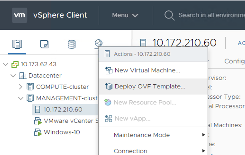
Deploy the NSX-T Manager OVA in vSphere. Download the OVA from the VMware software download site.
- Using the vSphere Client, right-click the vCenter cluster and select Deploy OVF Template.
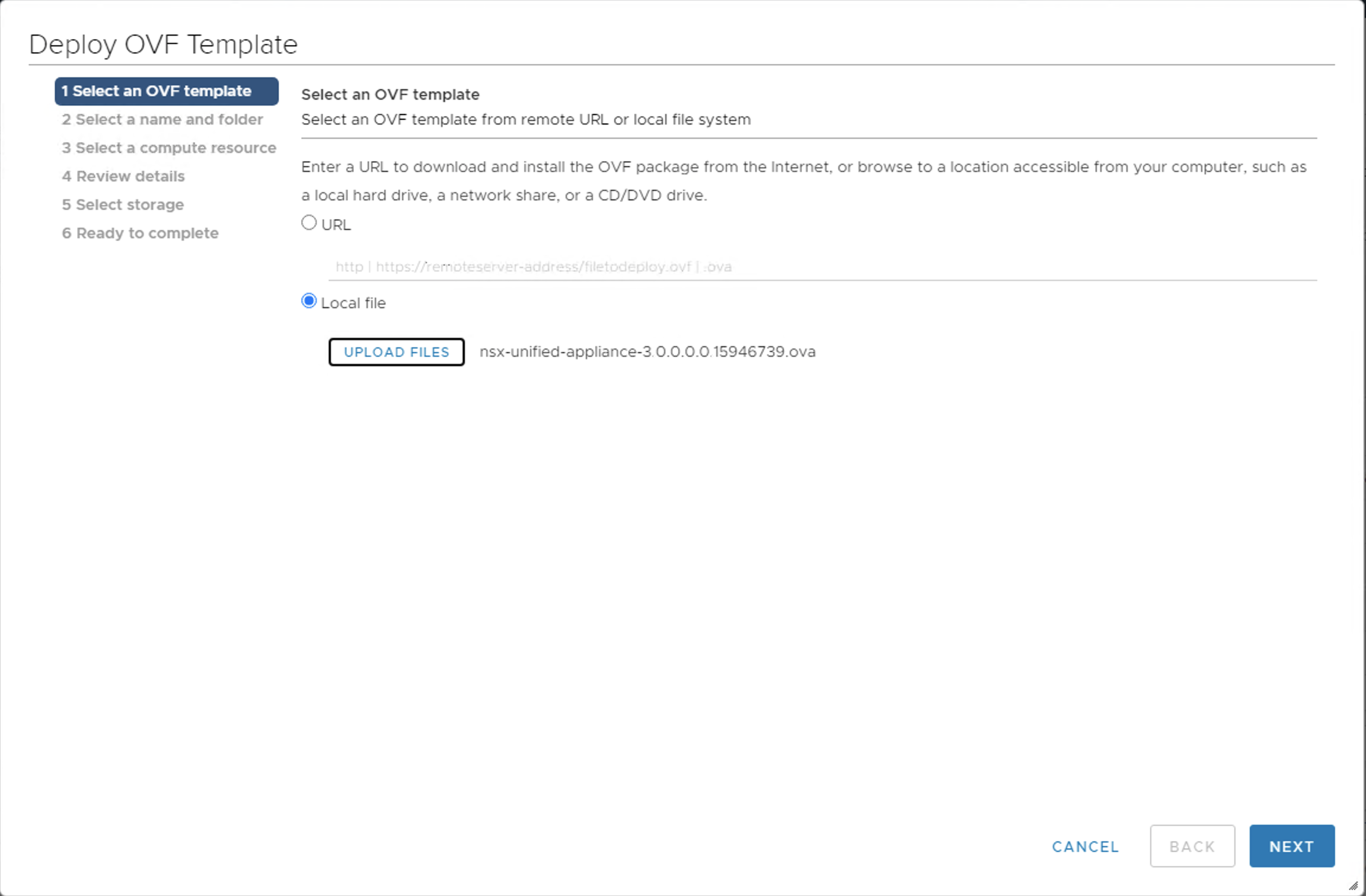
- At the Select an OVF Template screen, browse to and select the NSX Unified Appliance OVA file.
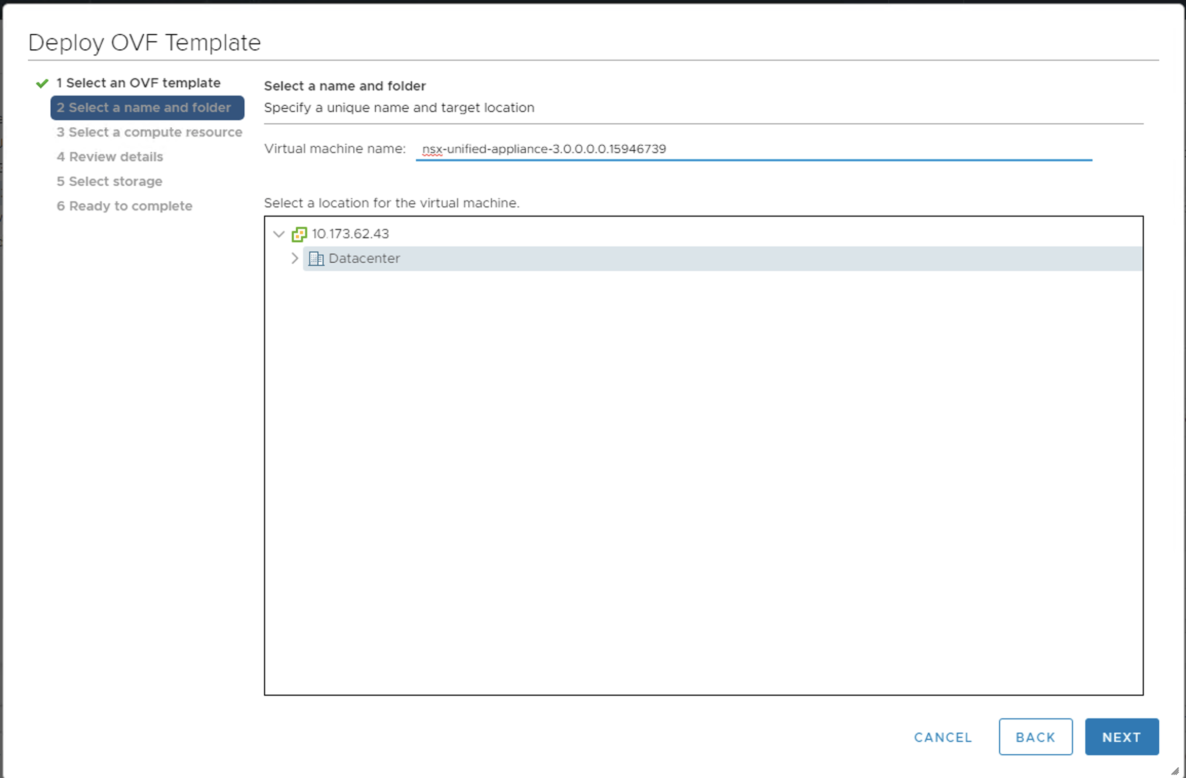
- At the Select a name and folder screen, select the target Datacenter object.
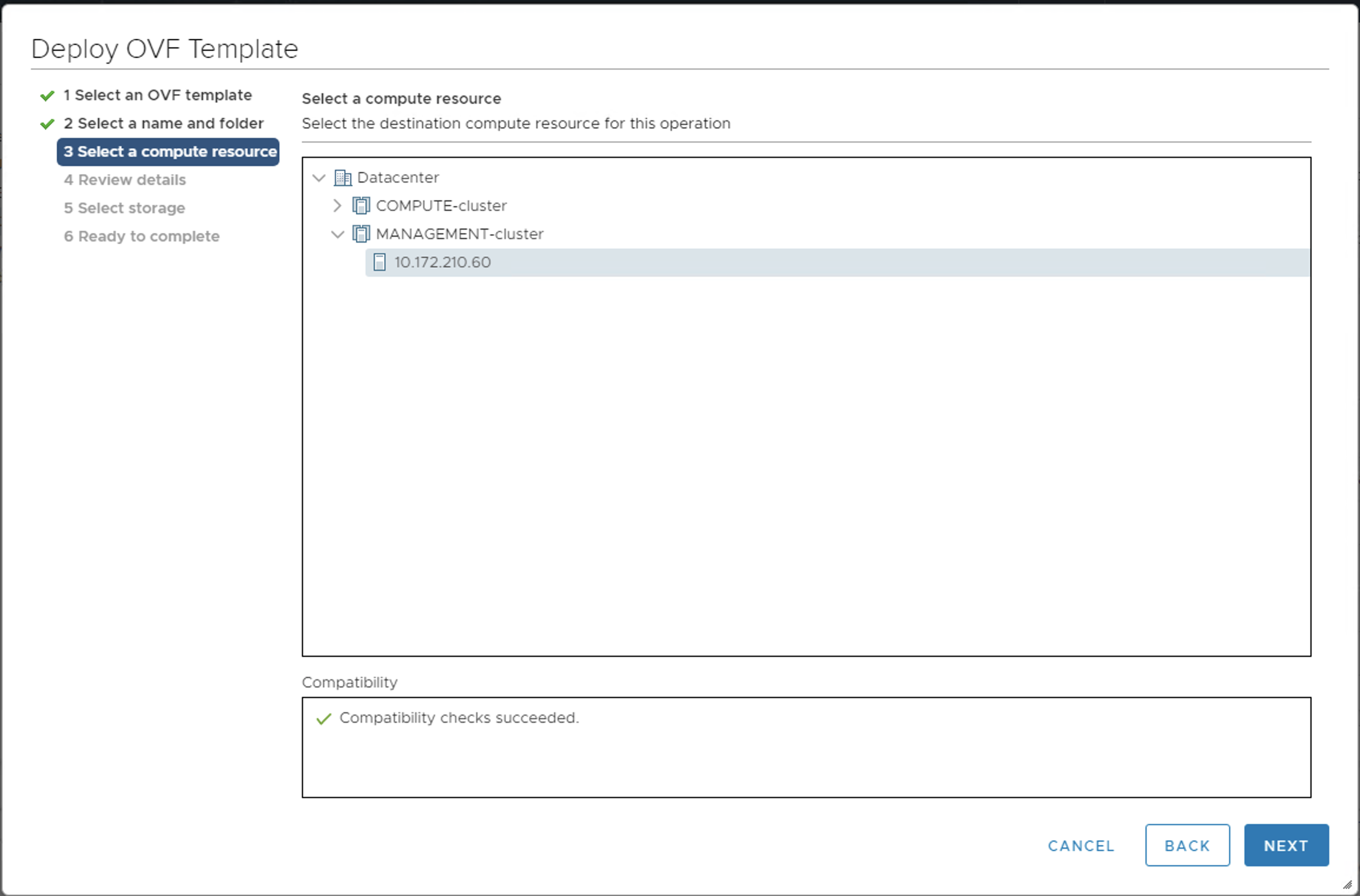
- At the Select a compute resource screen, select the target vCenter cluster.
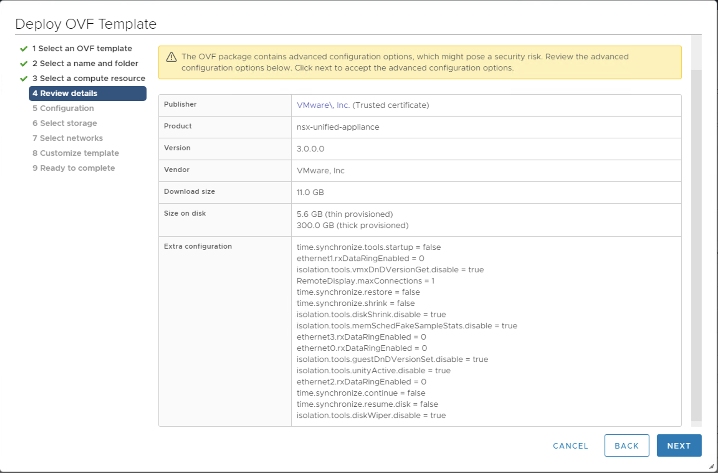
- Review the details.
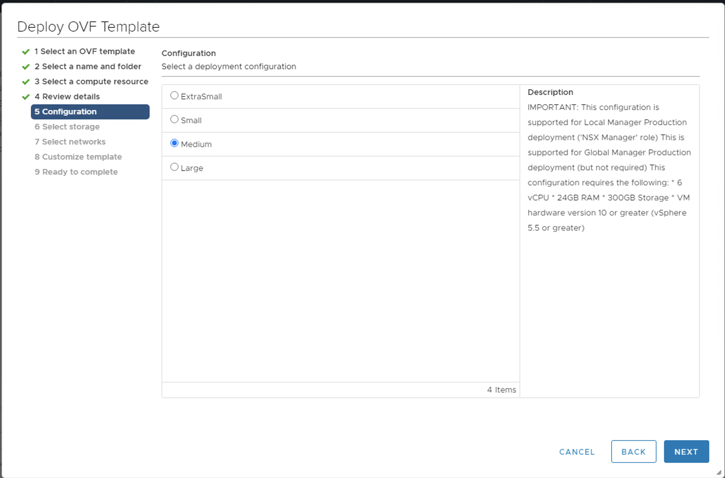
- At the Configuration screen, select at least Medium for the configuration size.
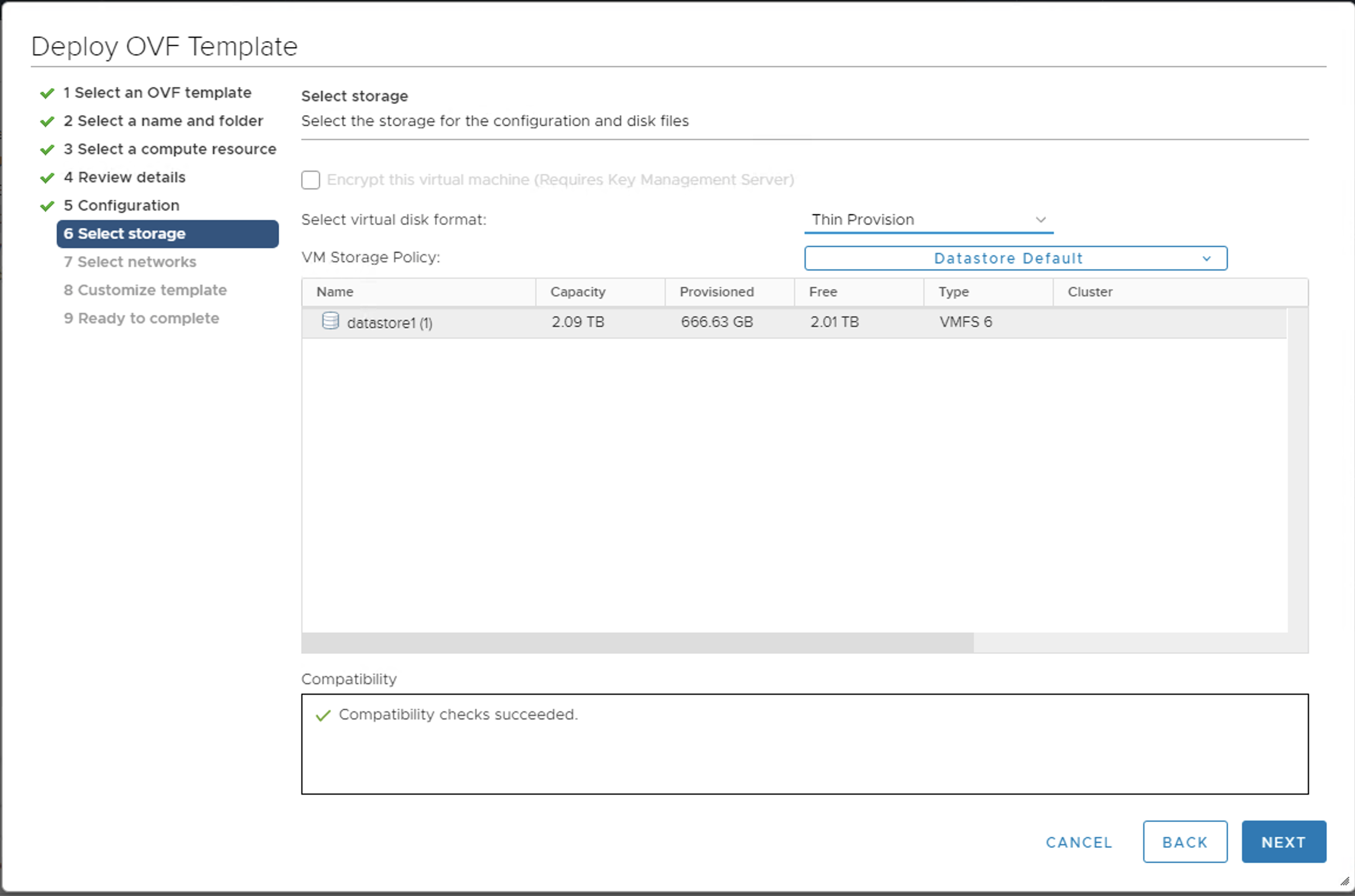
- At the Select storage screen, choose Thin Provision and the desired datastore.
- For Network1, enter the VLAN management network. For example,
PG-MGMT-VLAN-1548.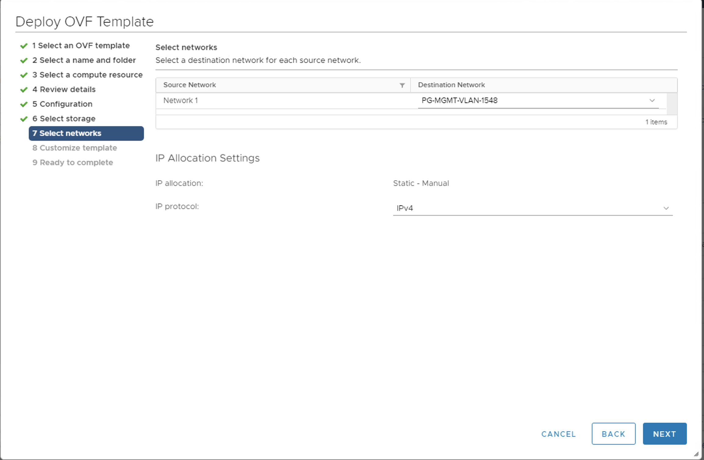
- Enter strong passwords for all user types.

- Enter the hostname. For example,
nsx-manager-1. - Enter the rolename. For example,
NSX Manager. - Enter the Gateway IP address. For example,
10.173.62.253. - Enter a public IP address for the VM. For example,
10.173.62.44. - Enter the Netmask. For example,
255.255.255.0.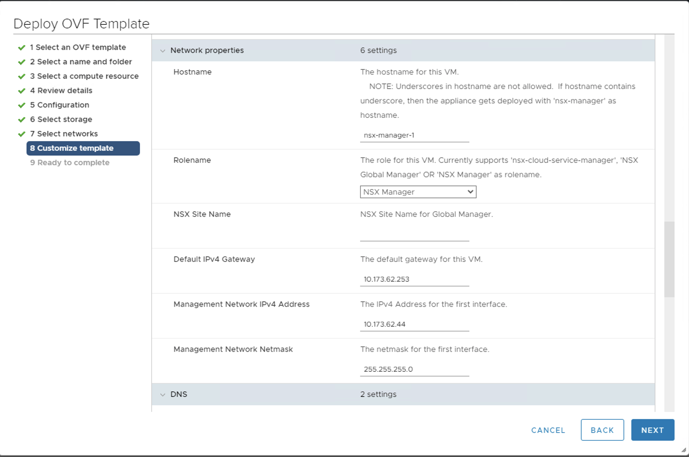
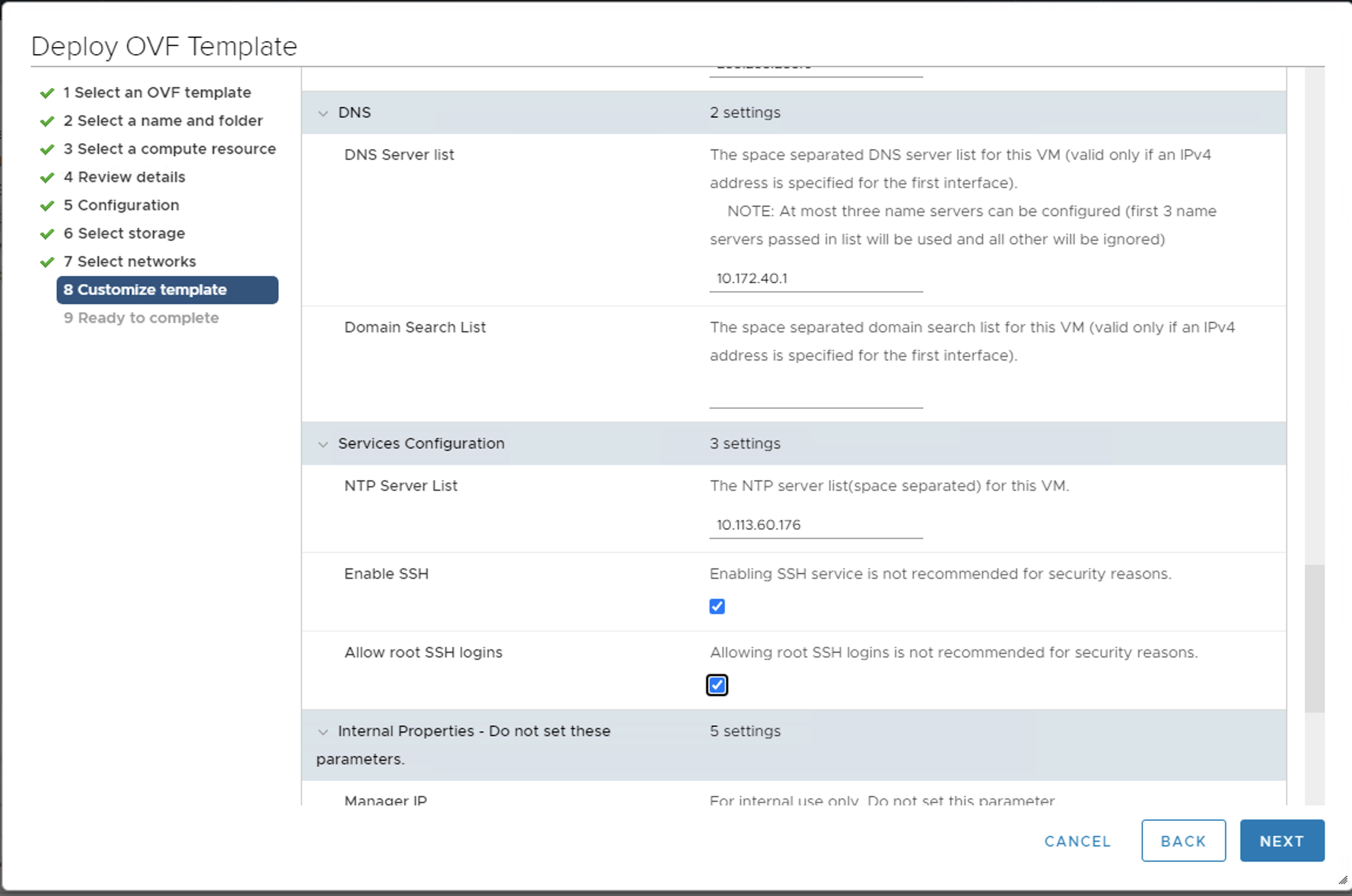
- Enter the DNS server. For example,
10.172.40.1. - Enter the
NTP server. For example,10.113.60.176. - Select the Enable SSH check box.
- Select the Allow SSH root logins check box.
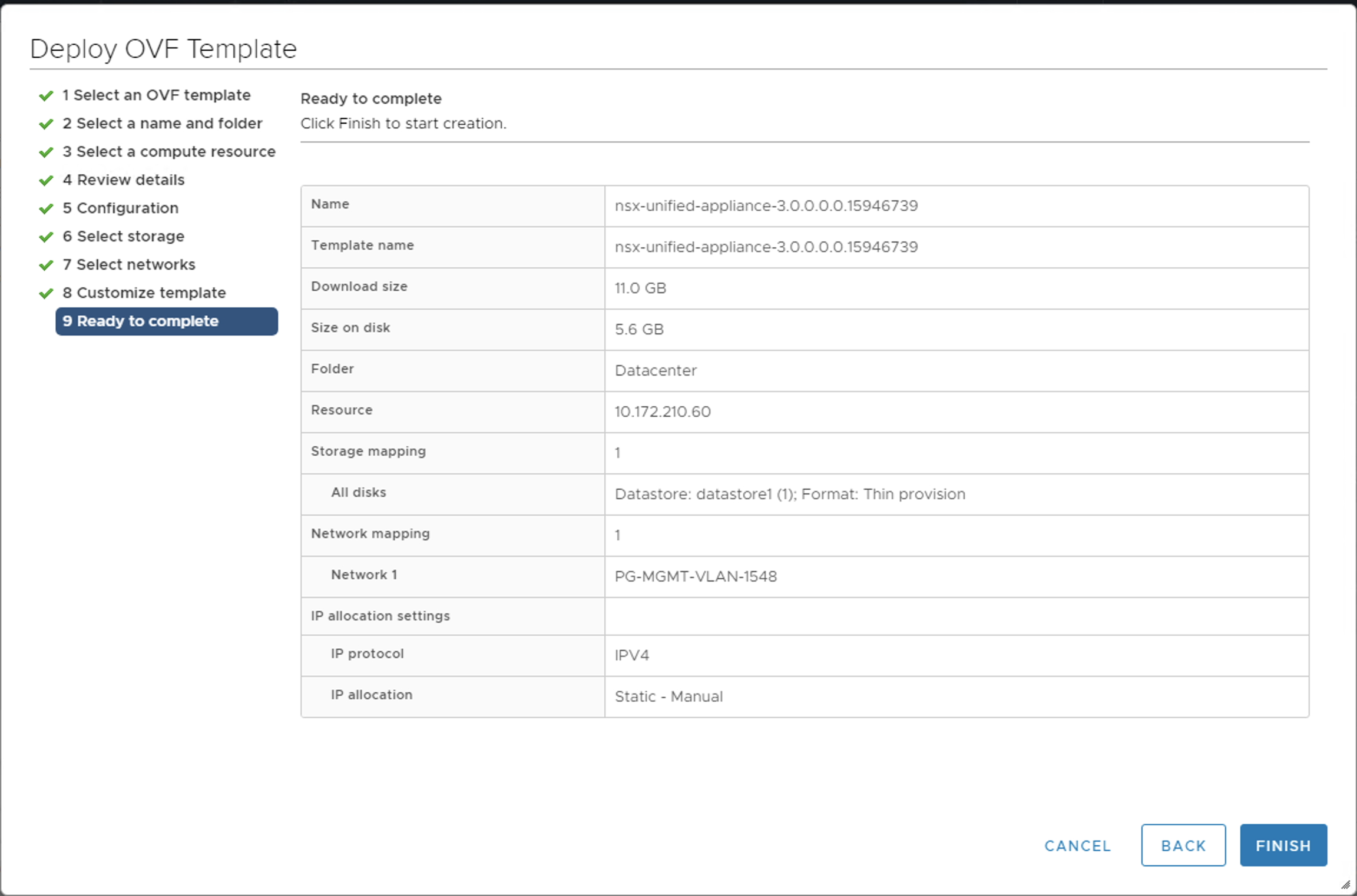
- Click Finish. The NSX-T Manager 1 starts deploying.
- Monitor the deployment in the Recent Tasks pane.
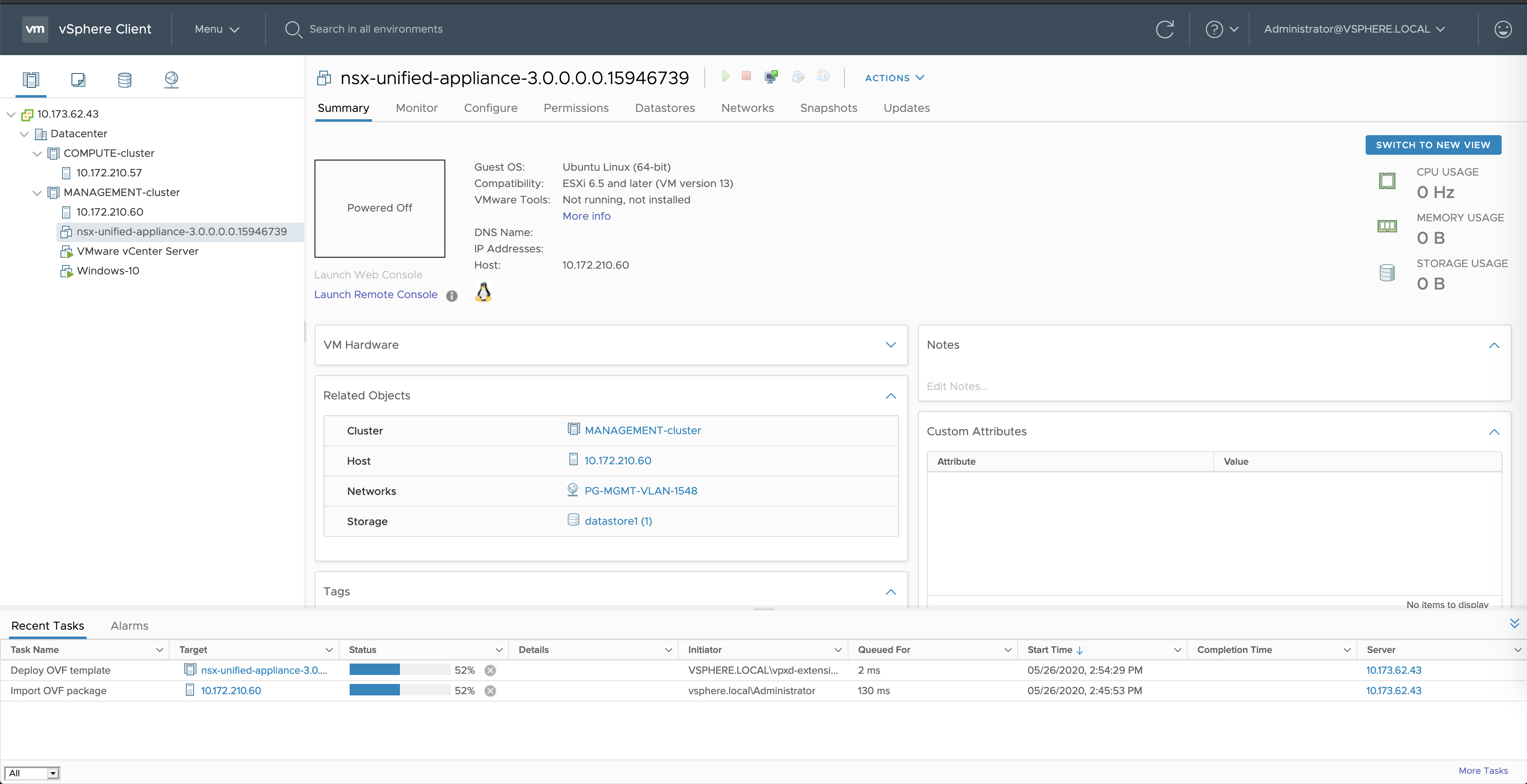
- When the deployment completes, select the VM to power the VM on.
- Access the NSX-T Manager 1 web console by navigating to the URL. For example,
https://10.173.62.44/.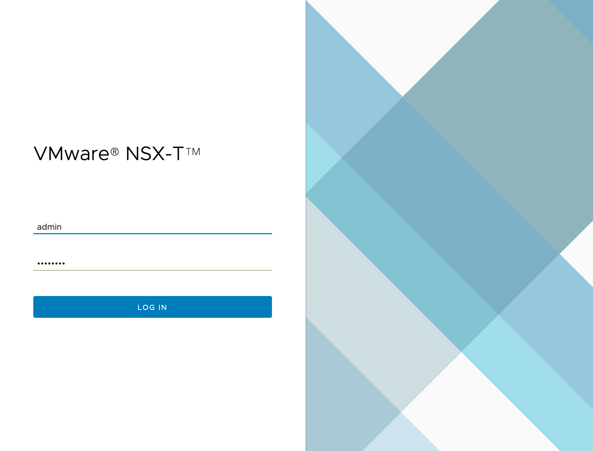
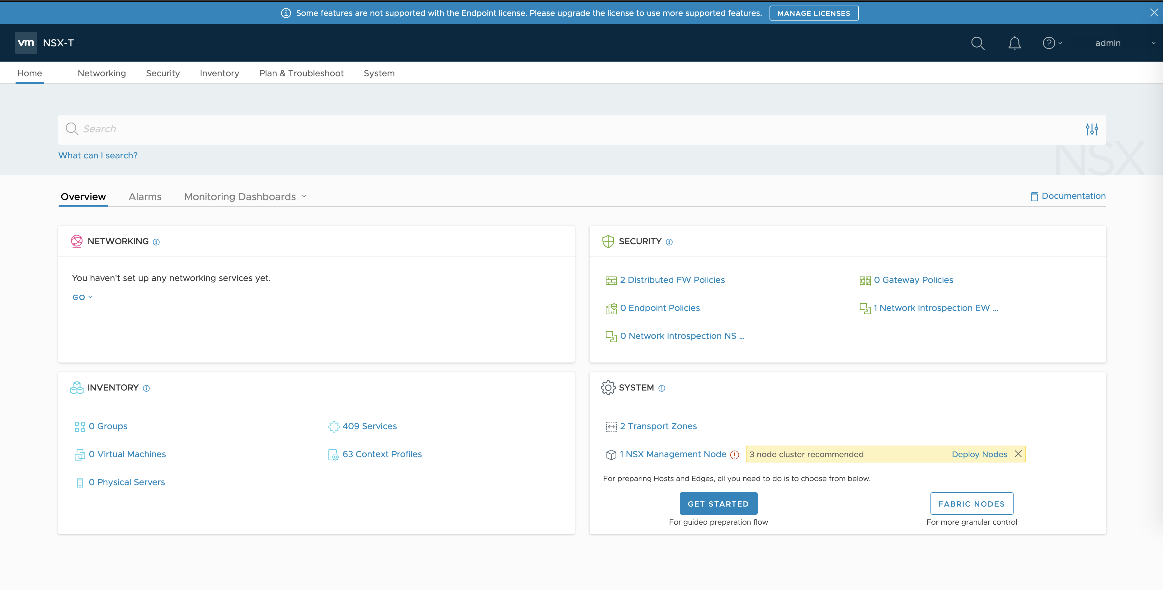
- Log in and verify the installation. Note the system message that a “3 node cluster” is recommended.
Add vCenter as the Compute Manager
A compute manager is required for NSX-T environments with multiple NSX-T Manager nodes. A compute manager is an application that manages resources such as hosts and VMs. For TKGI, use the vCenter Server as the compute manager.
Complete the following steps to add vCenter as the Compute Manager. For more information, see the NSX-T documentation.
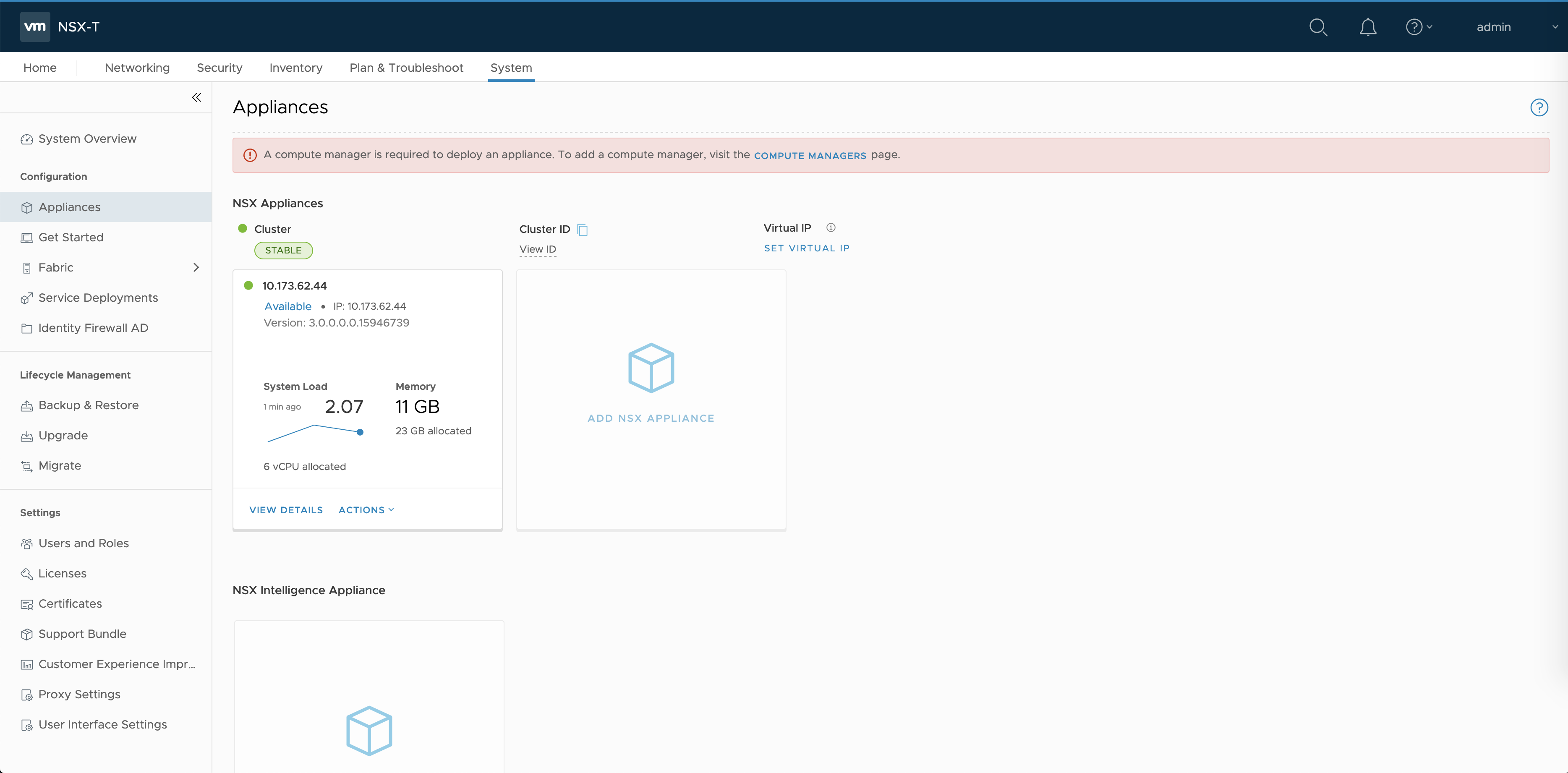
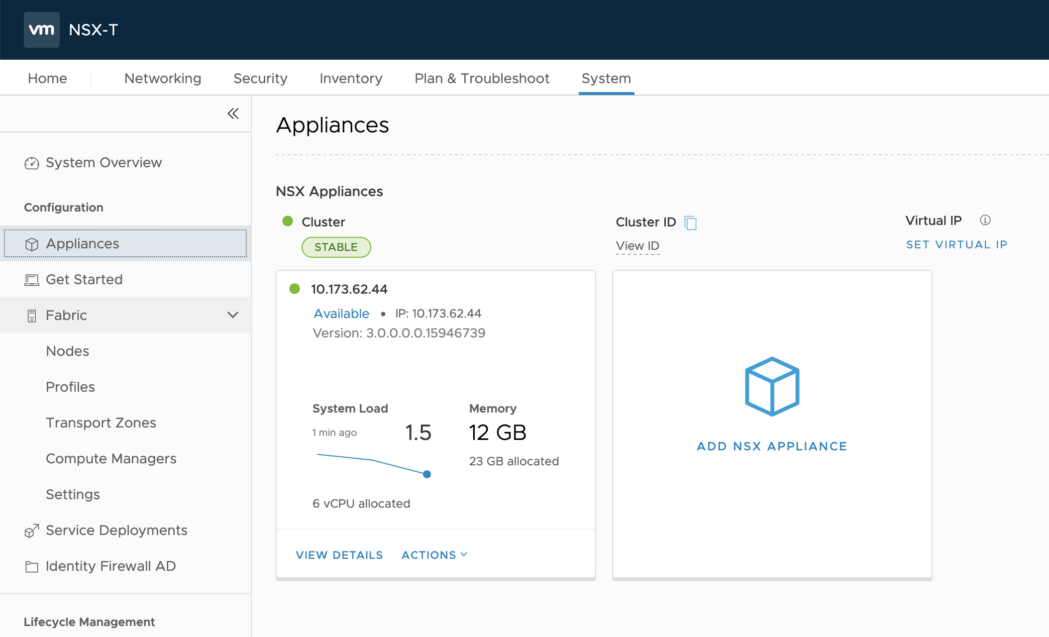
- In the NSX Management console, navigate to System > Appliances.
- Select Compute Managers.
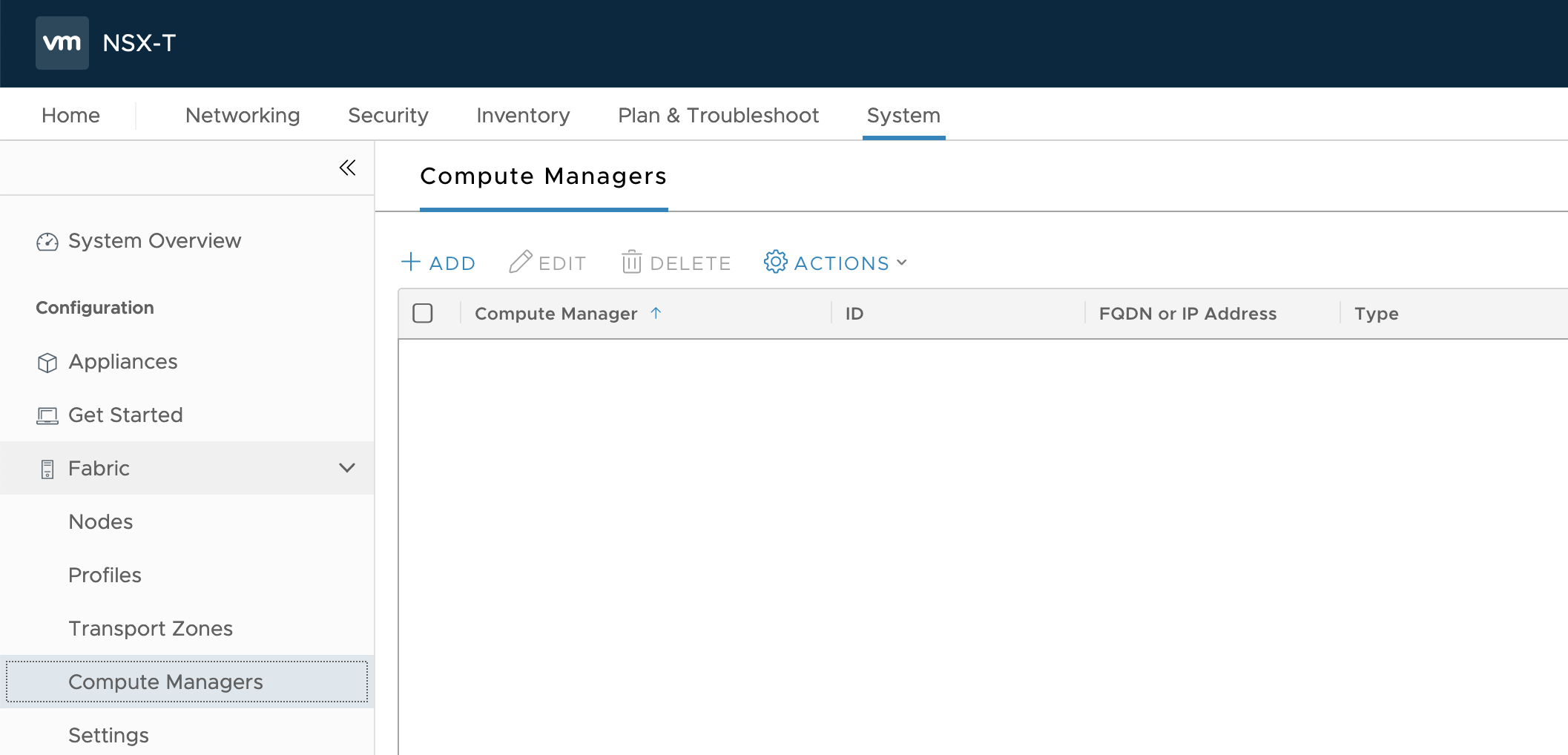
- Click Add.
- Enter a Name. For example, vCenter.
- Enter an IP address. For example,
10.173.62.43. - Enter the vCenter user name. For example,
[email protected]. - Set the Enable Trust toggle to Yes.
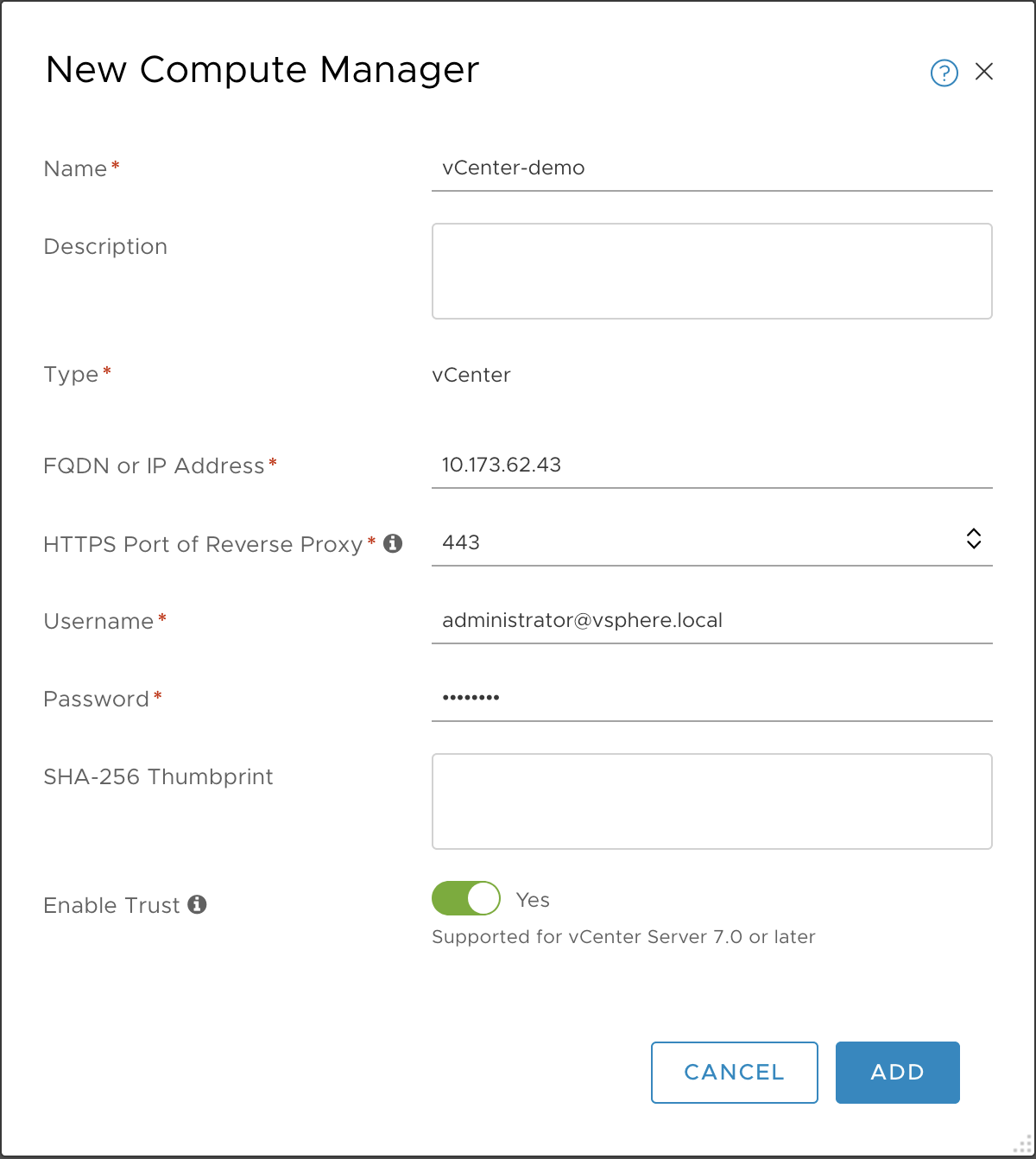
- Click Add.
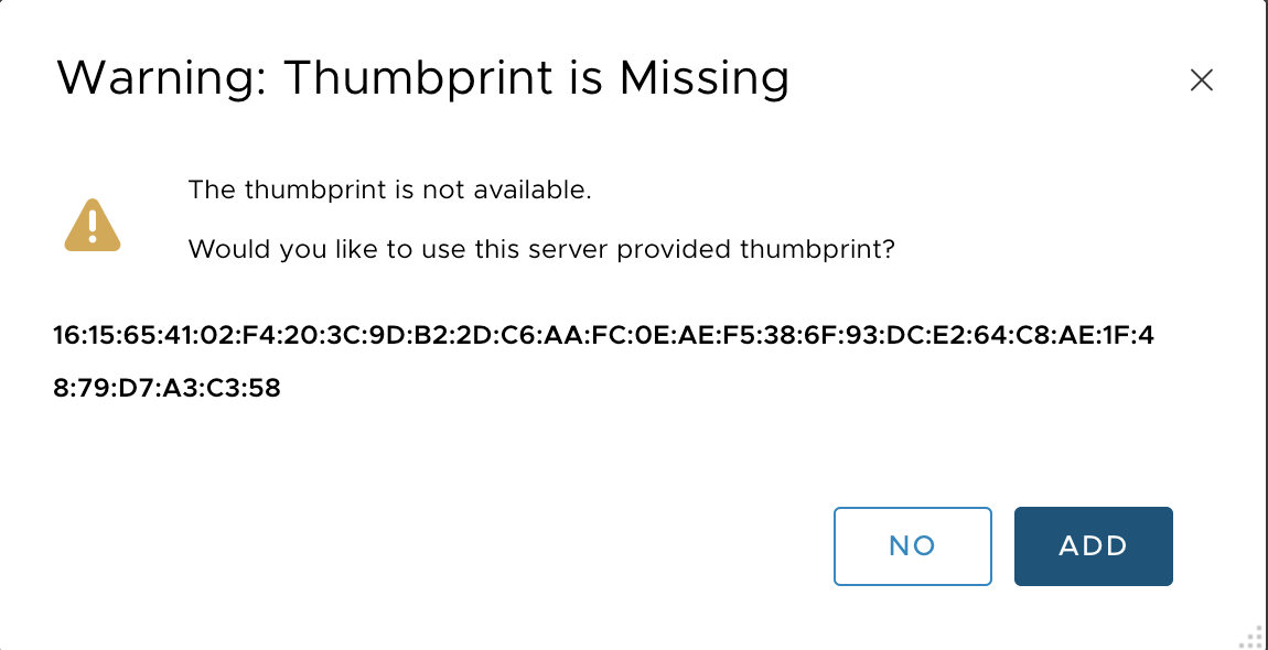
- Click Add again at the thumbprint warning.
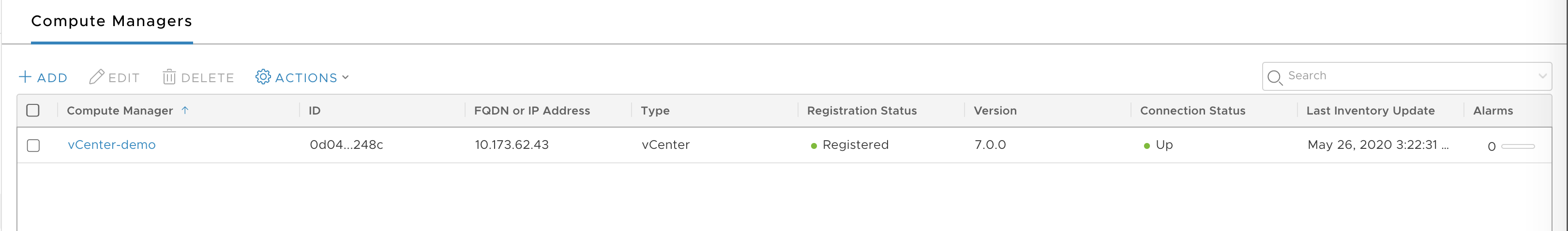
- Verify that the Compute Manager is added and registered.
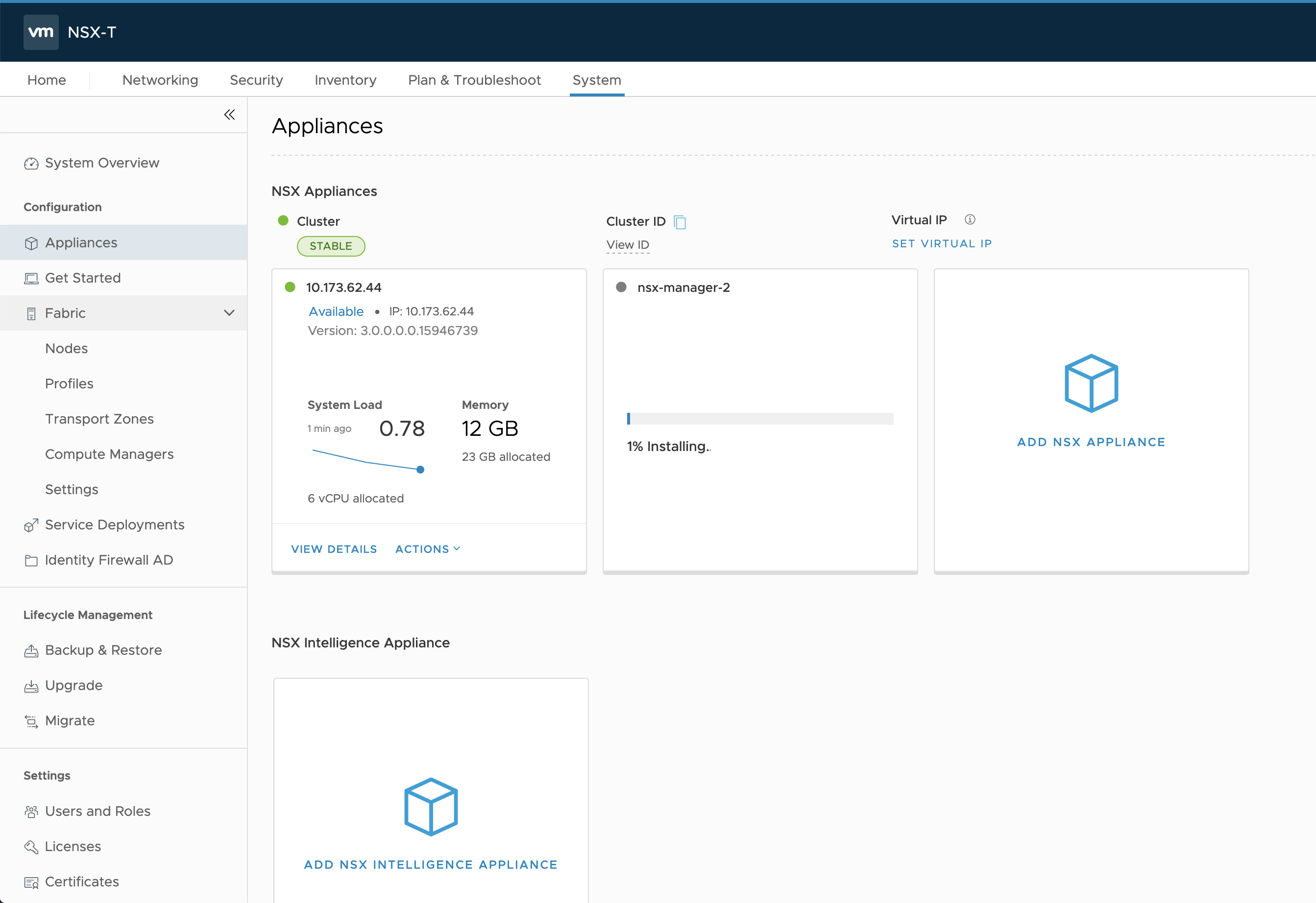
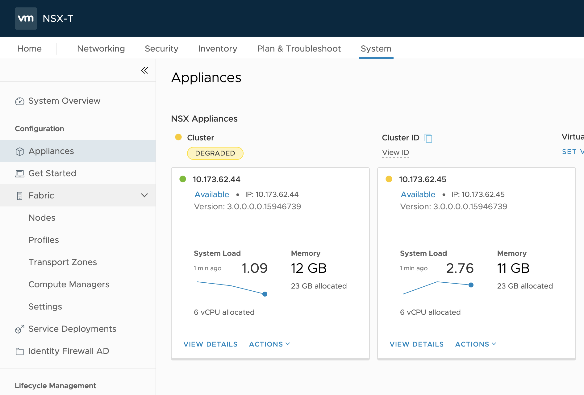
Deploy NSX-T Manager 2
Use the NSX-T Management Console to deploy an additional NSX-T Manager node as part of the NSX-T Management layer. For more information, see the NSX-T documentation.
- In the NSX Management Console, navigate to System > Appliances.
- Select Add NSX Appliance.
- Enter a hostname. For example,
nsx-manager-2. - Enter the Management IP/netmask. For example,
10.173.62.45/24. - Enter the Gateway. For example,
10.173.62.253. - For the Node size, select
medium.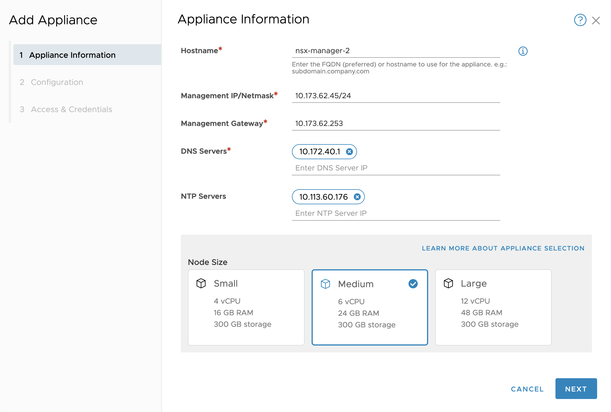
- For the Compute Manager, select
vCenter. - For the Compute Cluster, enter
MANAGEMENT-cluster. - For the Datastore, select the datastore. For example,
datastore2. - For the Virtual Disk Format, select
thin provision. - For the Network, select the VLAN management network. For example,
PG-MGMT-VLAN-1548.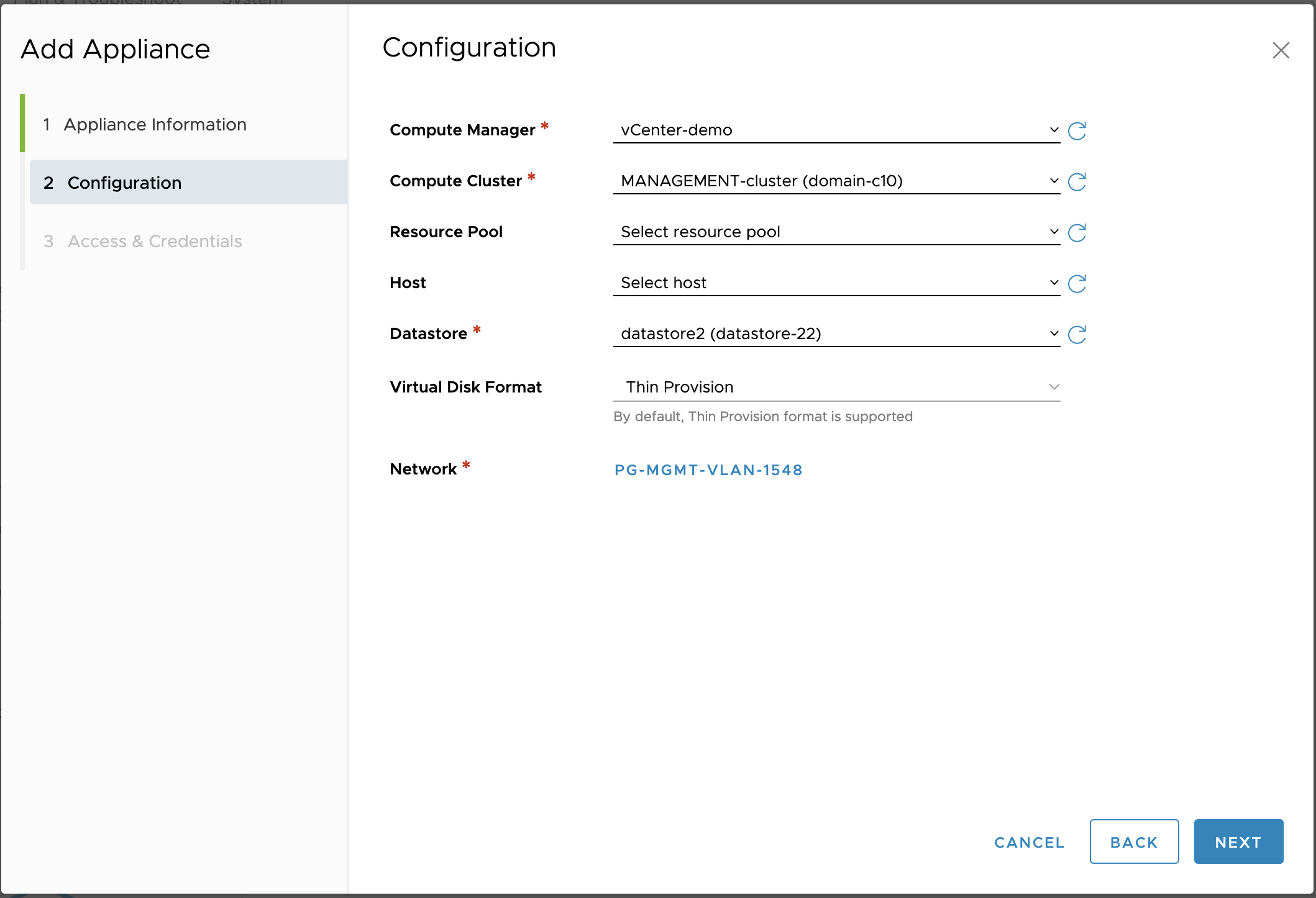
- Select Enable SSH.
- Select Enable root access.
- Enter a strong password.
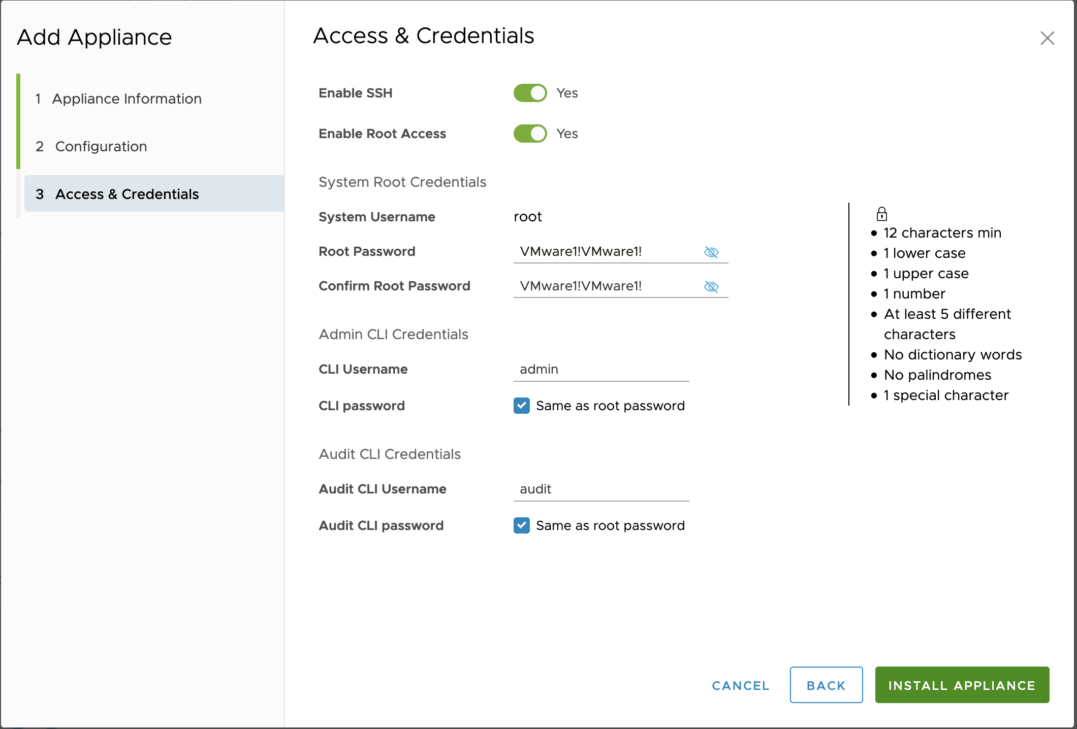
- Click Install Appliance.
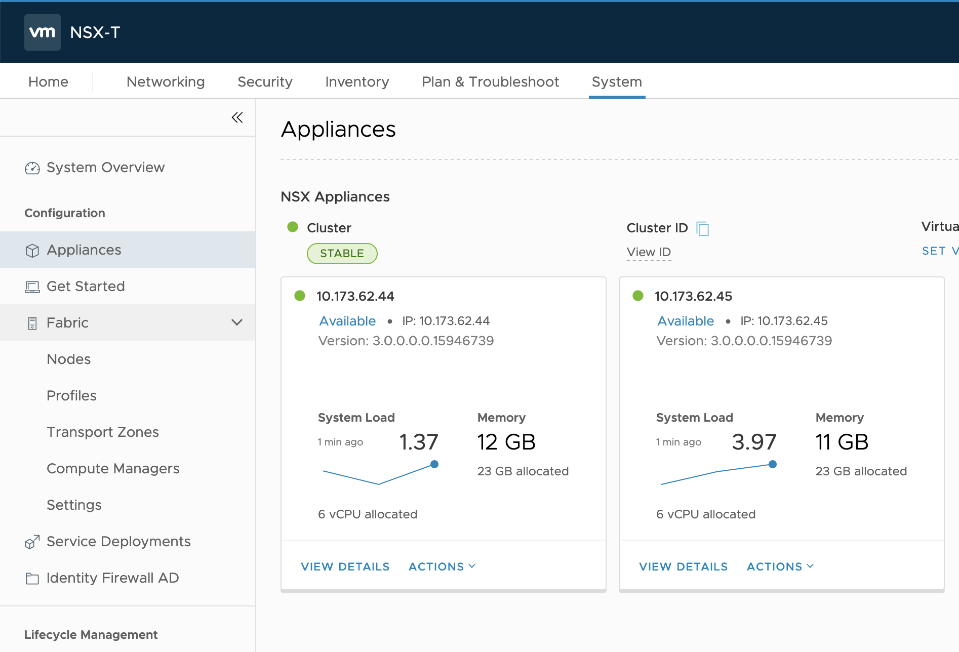
- Verify that the NSX-T Manager 2 appliance is added.
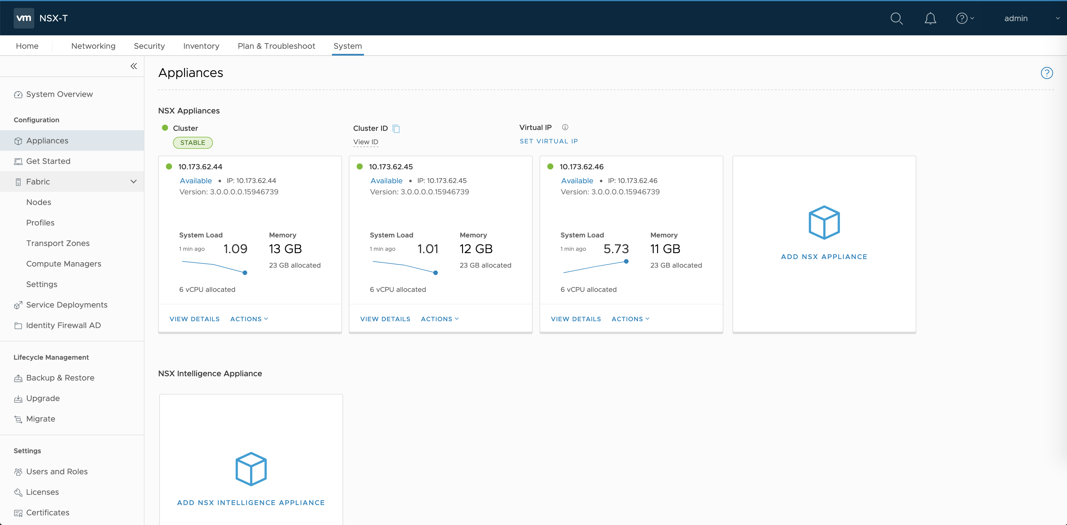
Deploy NSX-T Manager 3
Use the NSX-T Management Console to deploy a third NSX-T Manager node as part of the NSX-T Management layer. For more information, see the NSX-T documentation.
- In the NSX Management Console, navigate to System > Appliances.
- Select Add NSX Appliance.
- Enter a hostname. For example,
nsx-manager-3. - Enter the Management IP/netmask. For example,
10.173.62.46/24. - Enter the Gateway. For example,
10.173.62.253. - For the Node size, select
medium. - For the Compute Manager, select
vCenter. - For the Compute Cluster, enter
MANAGEMENT-cluster. - For the Datastore, select the datastore. For example,
datastore2. - For the Virtual Disk Format, select
thin provision. - For the Network, select the VLAN management network. For example,
PG-MGMT-VLAN-1548. - Select Enable SSH.
- Select Enable root access.
- Enter a strong password.
- Click Install Appliance.
- Verify that the NSX-T Manager 3 appliance is added.
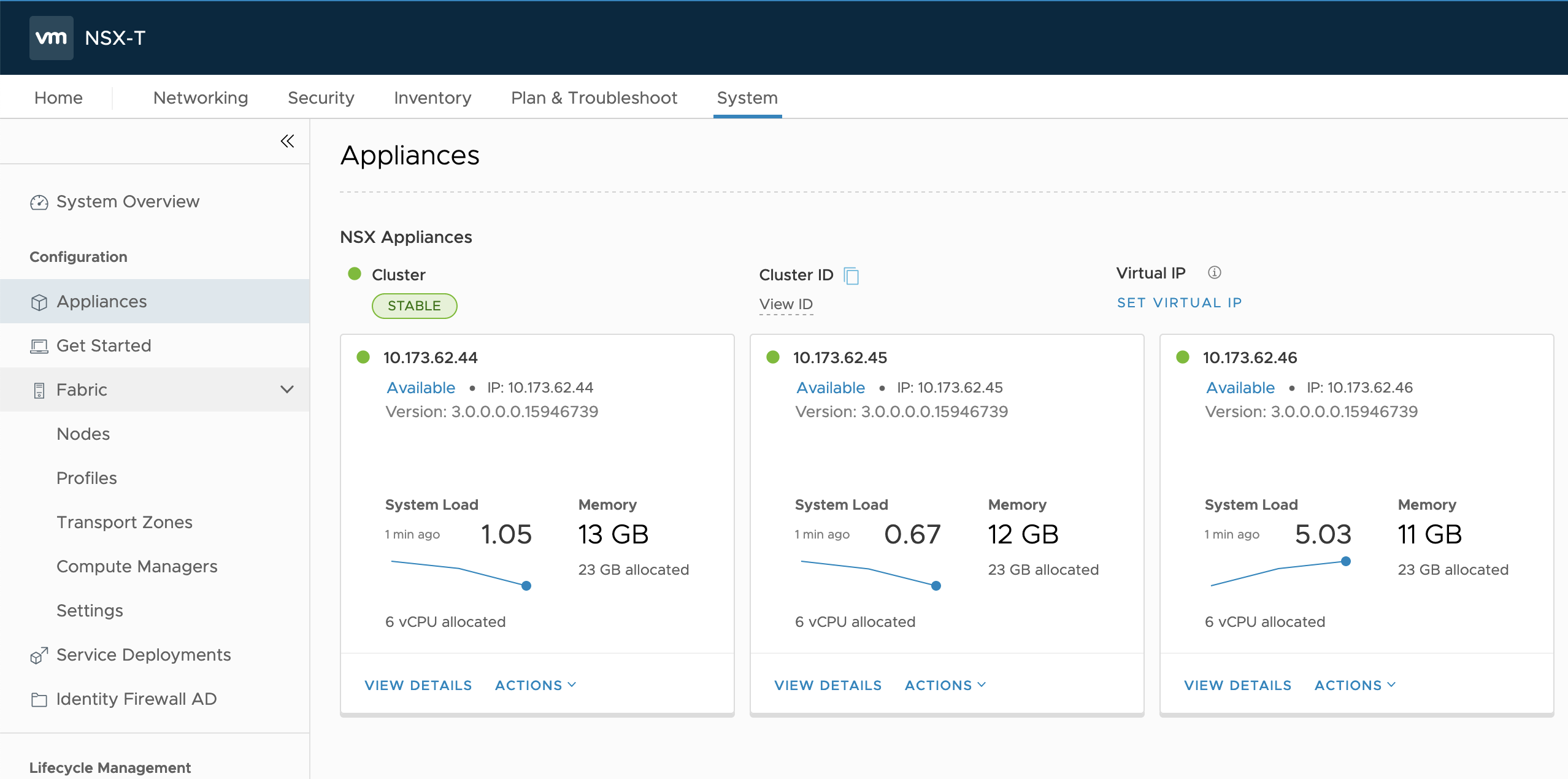
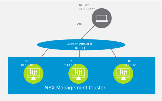
Configure the NSX-T Management VIP
The NSX-T Management layer includes three NSX-T Manager nodes. To support a single access point, assign a virtual IP Address (VIP) to the NSX-T Management layer. Once the VIP is assigned, any UI and API requests to NSX-T are redirected to the virtual IP address of the cluster, which is owned by the leader node. The leader node then routes the request forward to the other components of the appliance.
Using a VIP makes the NSX Management Cluster highly-available. If you need to scale, an alternative to the VIP is to provision a load balancer for the NSX-T Management Cluster. Provisioning a load balancer requires that NSX-T be fully installed and configured. VMware recommends that you configure the VIP now, then install a load balancer after NSX-T is installed and configured, if needed.
Complete the following instructions to create a VIP for the NSX Management Cluster. The IP address you use for the VIP must be part of the same subnet as the NSX-T Management nodes.
- In the NSX Management Console, navigate to System > Appliances.
- Click the Set Virtual IP button.
- Enter a Virtual IP address. For example,
10.173.62.47.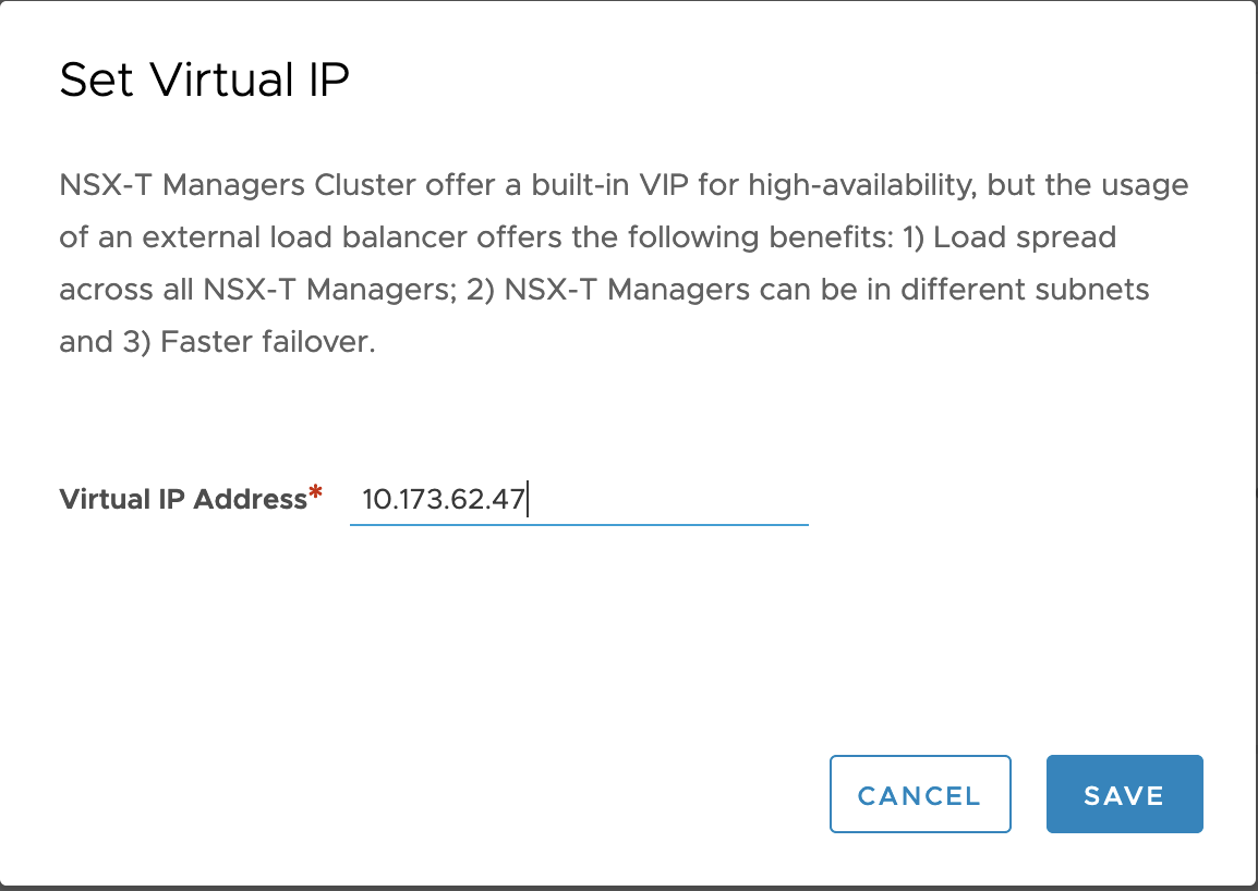
- Verify that the VIP is added.
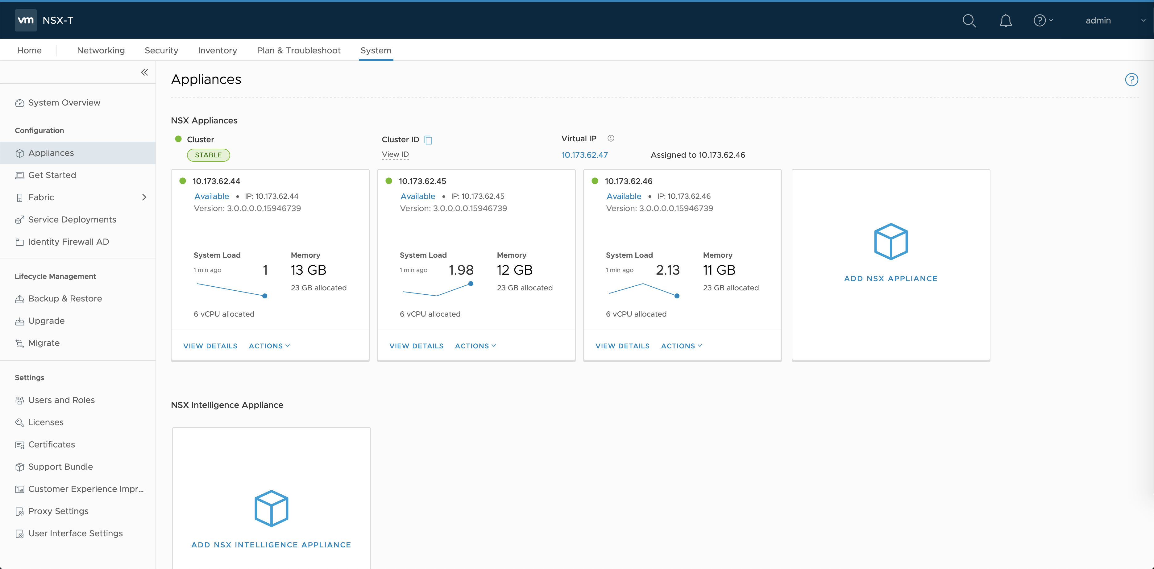
- Access the NSX-T Management console using the VIP. For example,
https://10.173.62.47/.
Enable the NSX-T Manager Interface
The NSX Management Console provides two user interfaces: Policy and Manager. TKGI requires the Manager interface for configuring networking and security objects. Do NOT use the Policy interface for TKGI objects.
- In the NSX-T Manager console, navigate to System > User Interface Settings.
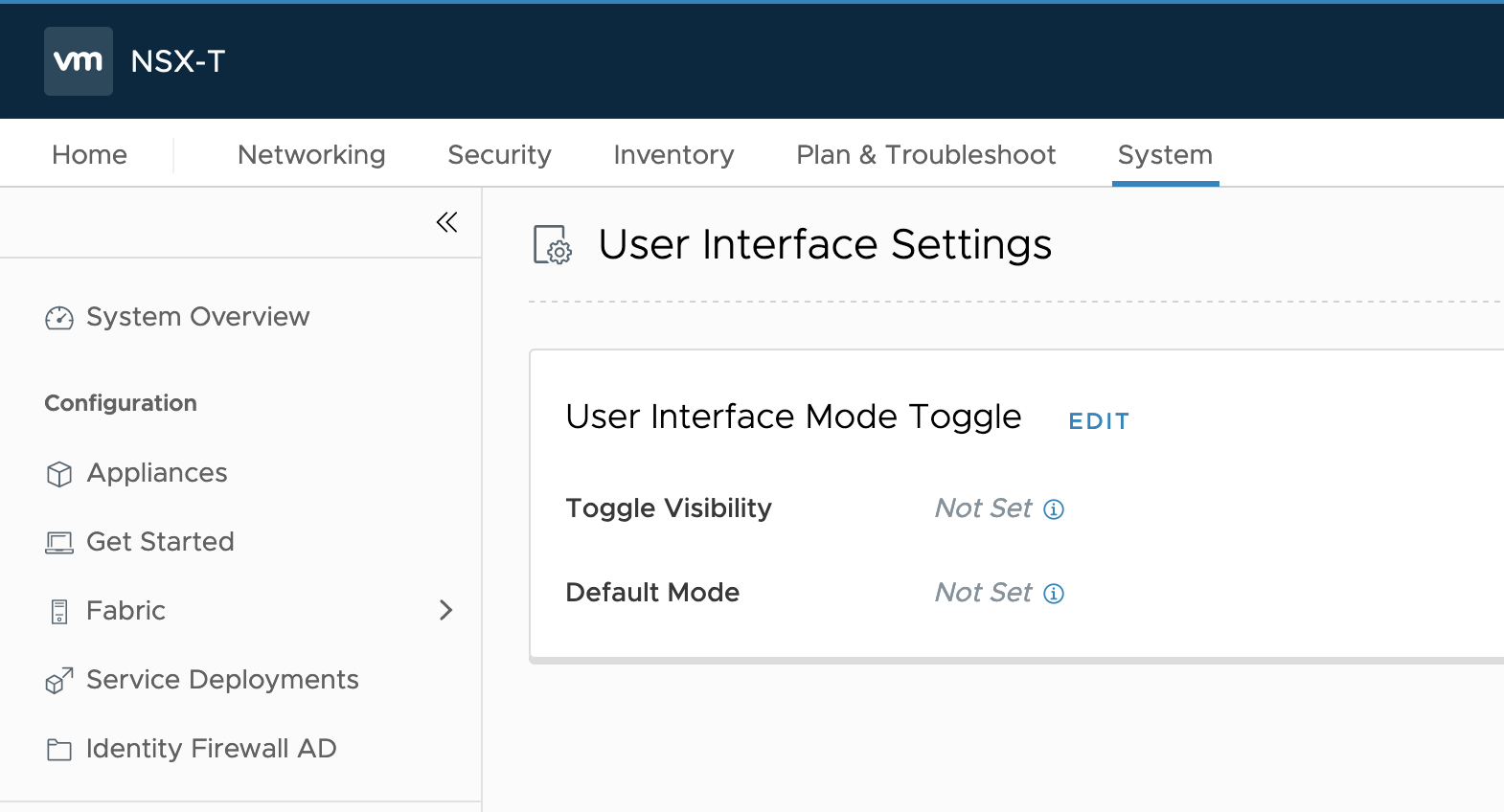
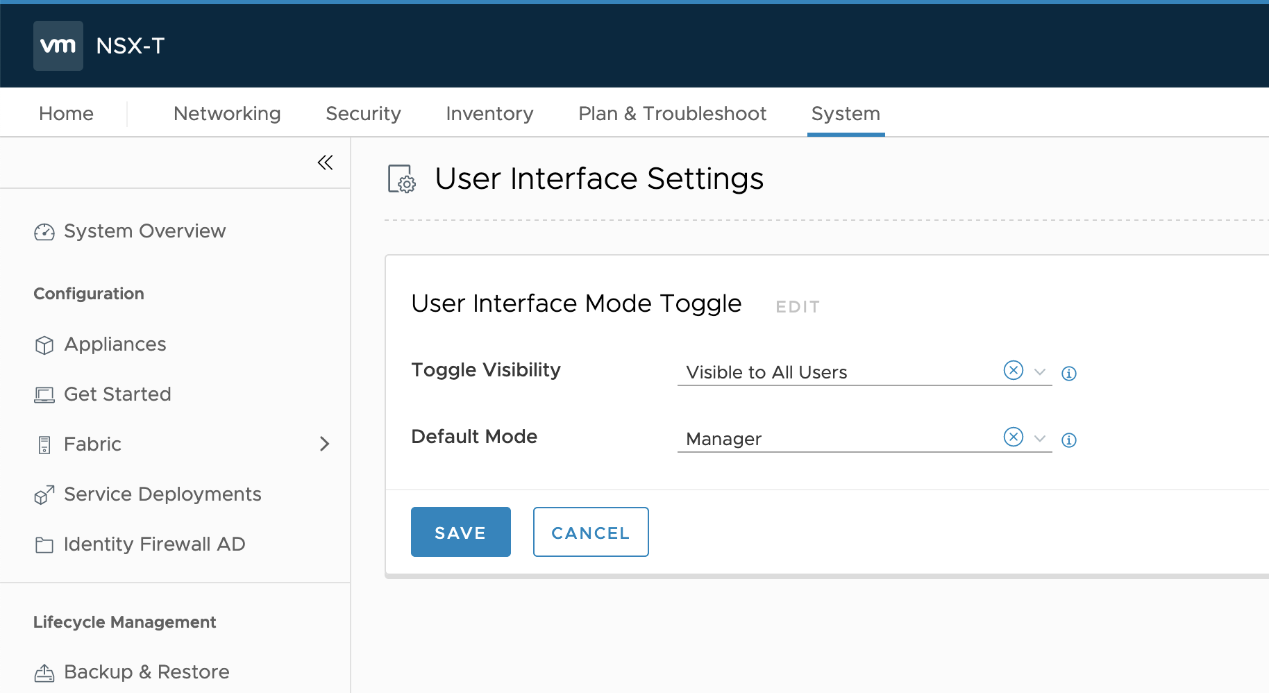
- Click Edit.
- For the Toggle Visibility field, select Visible to all Users.
- For the Default Mode field, select Manager.
- Click Save.
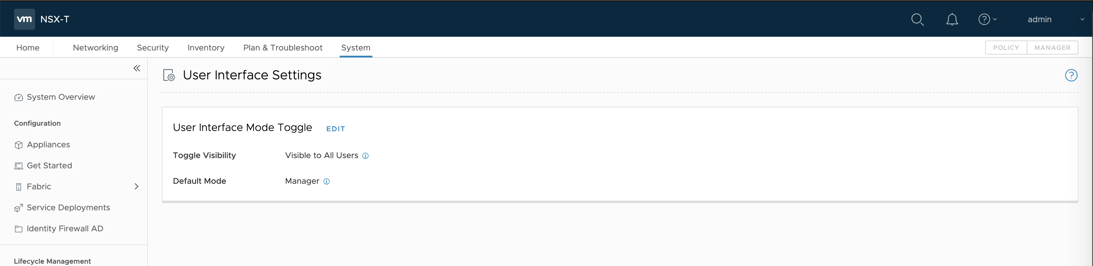
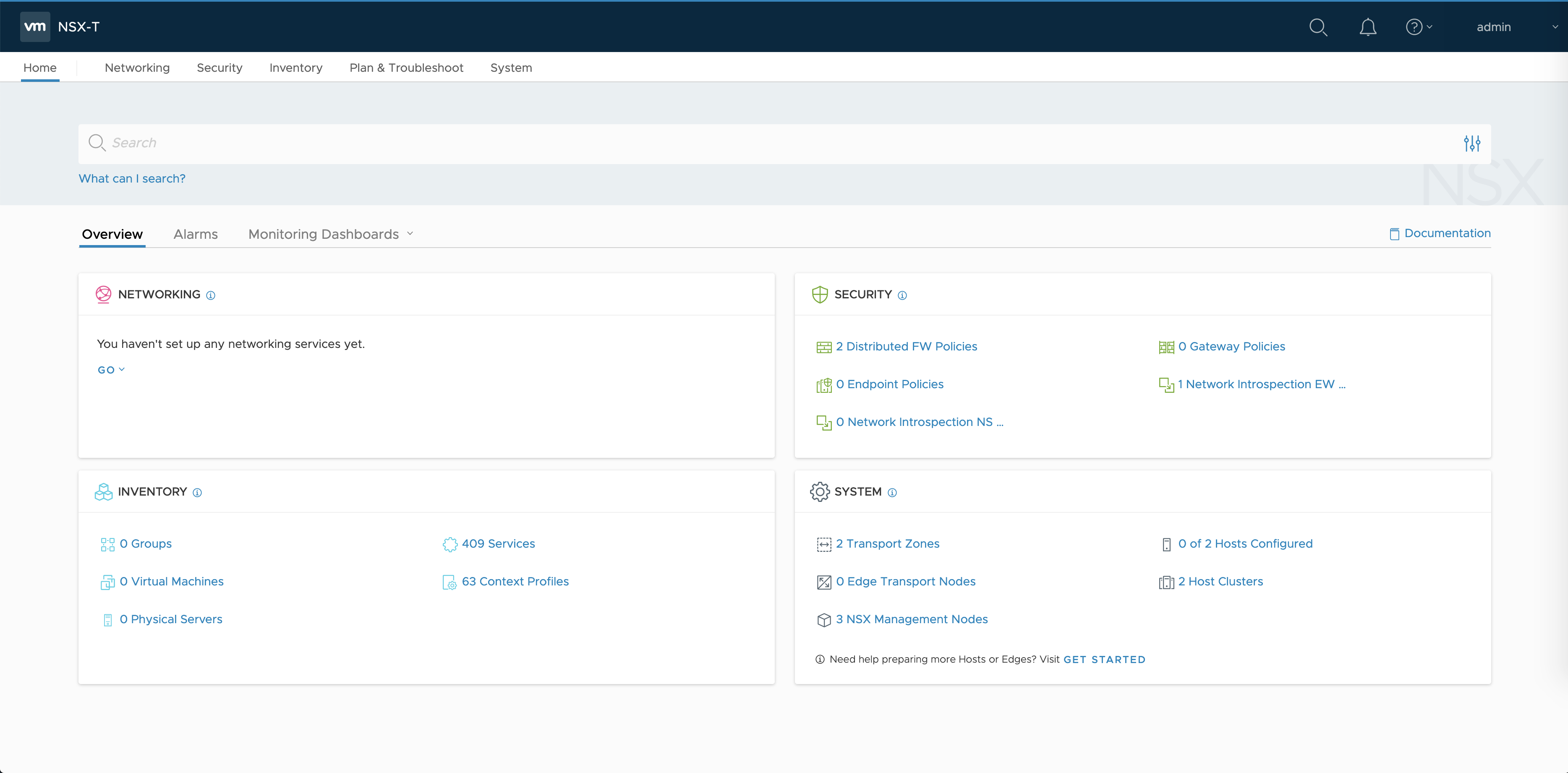
- Refresh the NSX-T Manager Console and navigate to an area of the console that is not listed under System.
- In the upper-right area of the console, verify that the Manager option is enabled.
Add the NSX-T Manager License
If you do not add the proper NSX-T license, you will receive an error when you try to deploy an Edge Node VM.
- In the NSX-T Manager console, navigate to System > Licenses.
- Add the NSX Data Center Advanced (CPU) license.
- Verify that the license is added.
Generate and Register the NSX-T Management SSL Certificate and Private Key
An SSL certificate is automatically created for each NSX-T Manager. You must also generate a certificate for the NSX-T Manager VIP.
To generate a certificate for the NSX-T Manager VIP, see Generate and Register the NSX-T Management TLS Certificate and Private Key.
Create an IP Pool for TEP
Tunnel endpoints (TEPs) are the source and destination IP addresses used in the external IP header to identify the ESXi hosts that originate and end the NSX-T encapsulation of overlay frames. The TEP addresses do not need to be routable so you can use any random IP addressing scheme you want. For more information, see the NSX-T Data Center documentation.
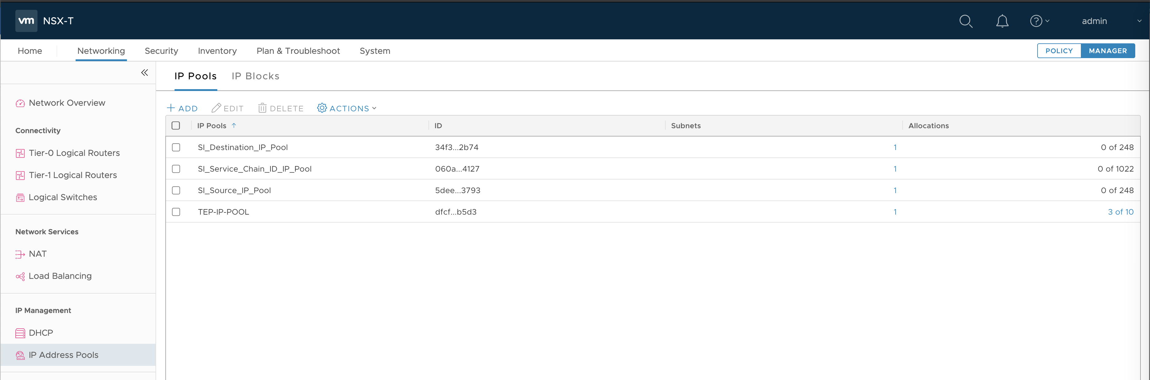
- In the NSX-T Management Console, select the Manager interface (upper right).
- Navigate to Networking > IP Address Pool.
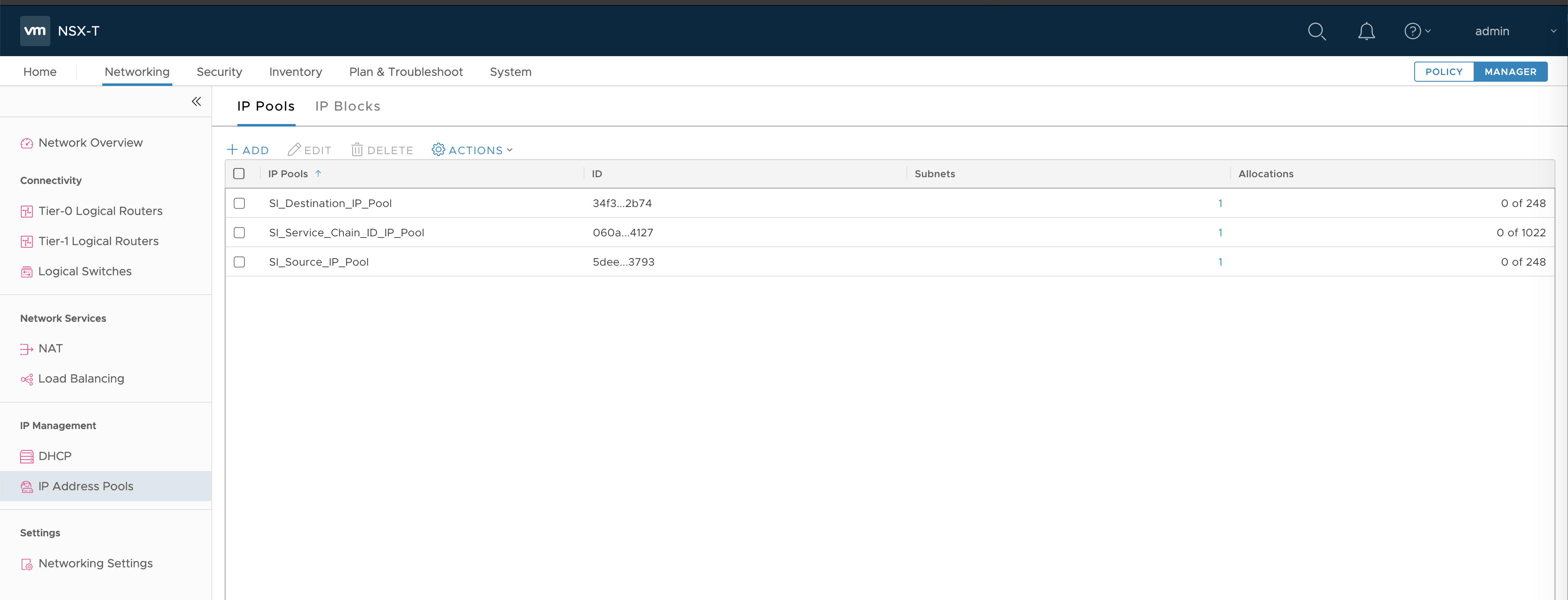
- Click Add.
- Enter a Name. For example,
TEP-IP-POOL. - Enter an IP range. For example,
192.23.213.1 - 192.23.213.10. - Enter a CIDR address. For example,
192.23.213.0/24.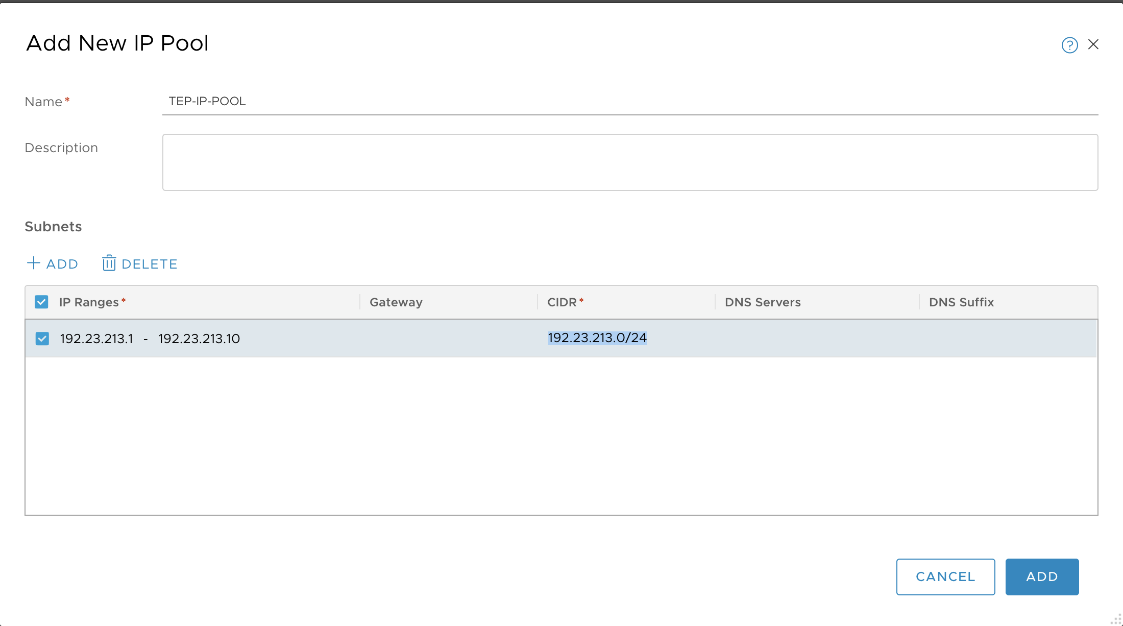
- Click Add.
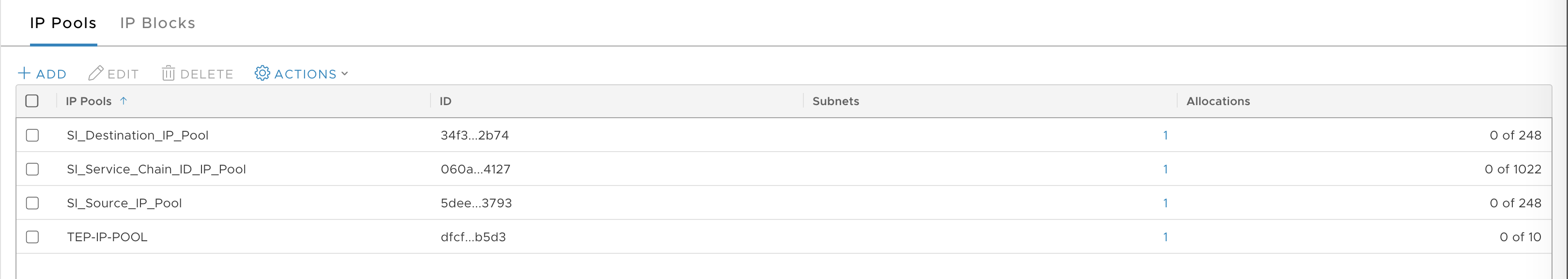
- Verify that the pool is added.
Configure Transport Zones
See Configuring NSX-T Data Center v3.1 Transport Zones and Edge Node Switches for TKGI.
Configure vSphere Networking for ESXi Hosts
In this section, you configure the vSphere networking and port groups for ESXi hosts (the vSwitch). If you have created separate vSphere clusters for Management and Compute, perform this operation on each ESXi host in the Management cluster. If you have not created separate vSphere clusters, perform this operation on each ESXi host in the cluster.
The following instructions describe how to configure a vSphere Virtual Standard vSwitch (VSS). For production environments, it is recommended that you configure a Virtual Distributed vSwitch (VDS). You configure the VDS from the vCenter Networking tab and then add the ESXi hosts to the VDS. The configuration settings for the VDS are similar to the VSS configuration described below. For instructions on configuring the VDS, see Create a vSphere Distributed Switch in the vSphere 7 documentation.
For more information, see the Release Notes for details about TKGI support for vSphere 7 VDS for NSX-T transport node traffic.
Create vSwitch Port-Groups for Edge Nodes
Create vSwitch Port-Groups for the Edge Nodes on the ESXi hosts in the MANAGEMENT-cluster.
For each ESXi host in the MANAGEMENT-cluster, create the following vSwitch Port Groups:
- EDGE-VTEP-PG: VLAN 3127
-
EDGE-UPLINK-PG: VLAN trunk (All (4095))
-
Log in to the vCenter Server.
- Select the ESXi host in the MANAGEMENT-cluster.
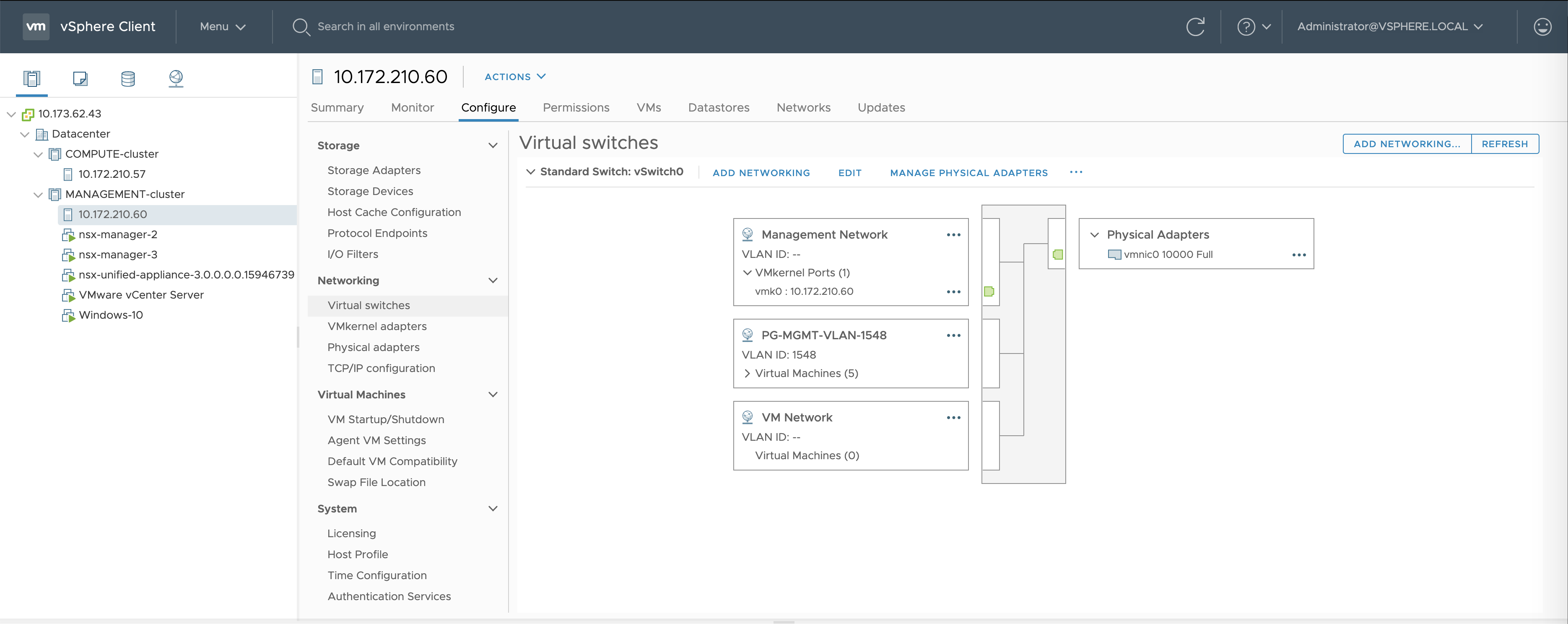
- Select Configure > Virtual switches.
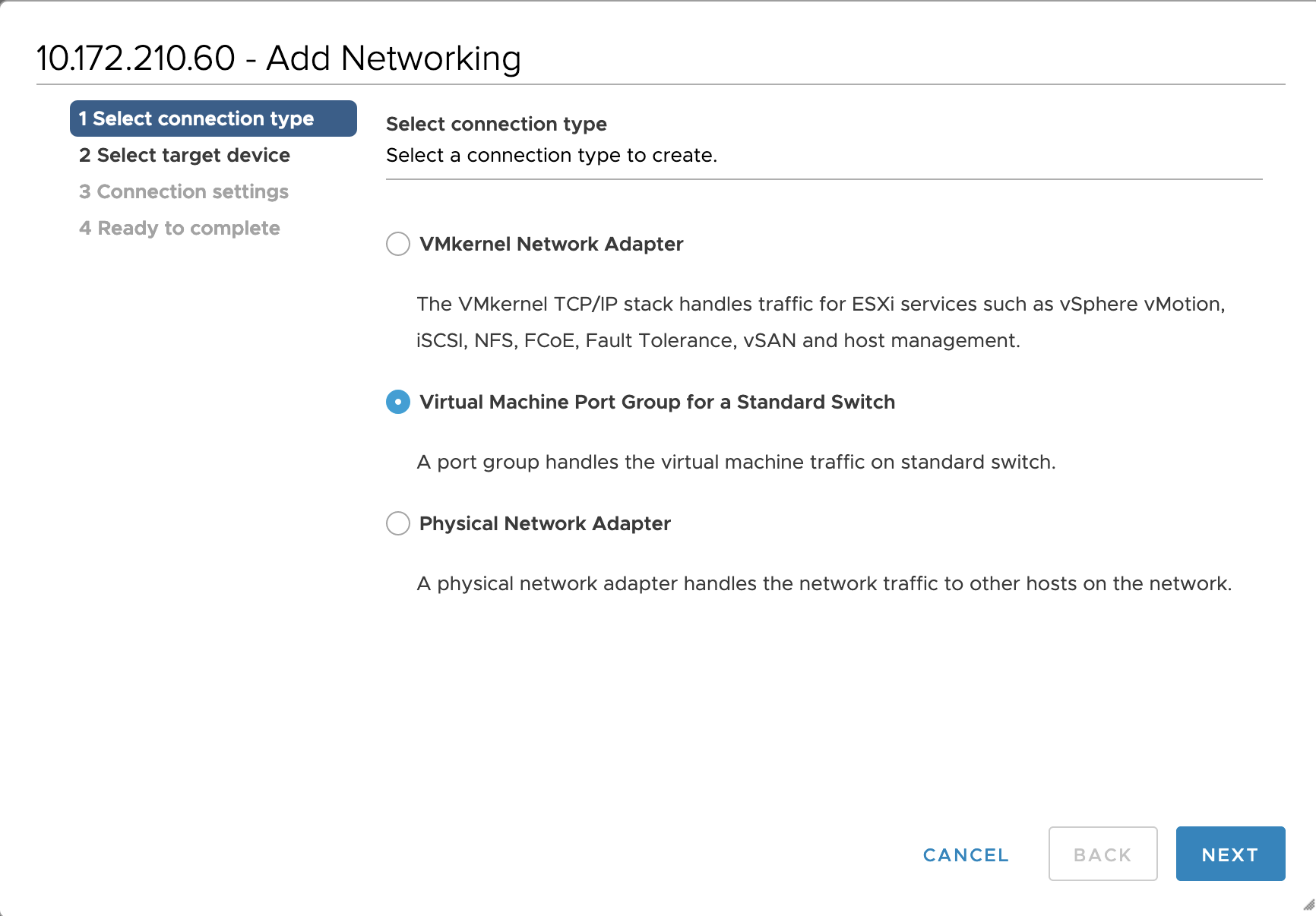
- Select Add Networking (upper right).
- Select the option Virtual Machine Port Group for a Standard Switch and click Next.
- Select the existing standard switch named
vSwitch0and click Next.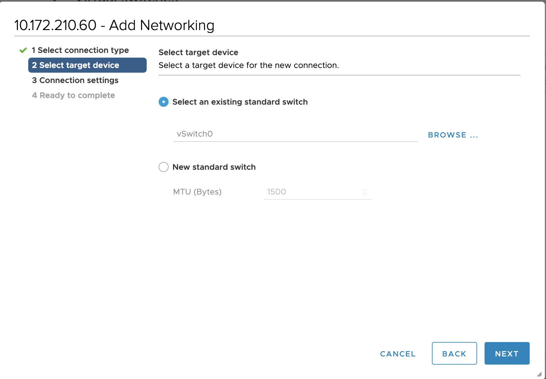
- Enter a Network Label. For example,
EDGE-VTEP-PG. - Enter a VLAN ID. For example,
3127.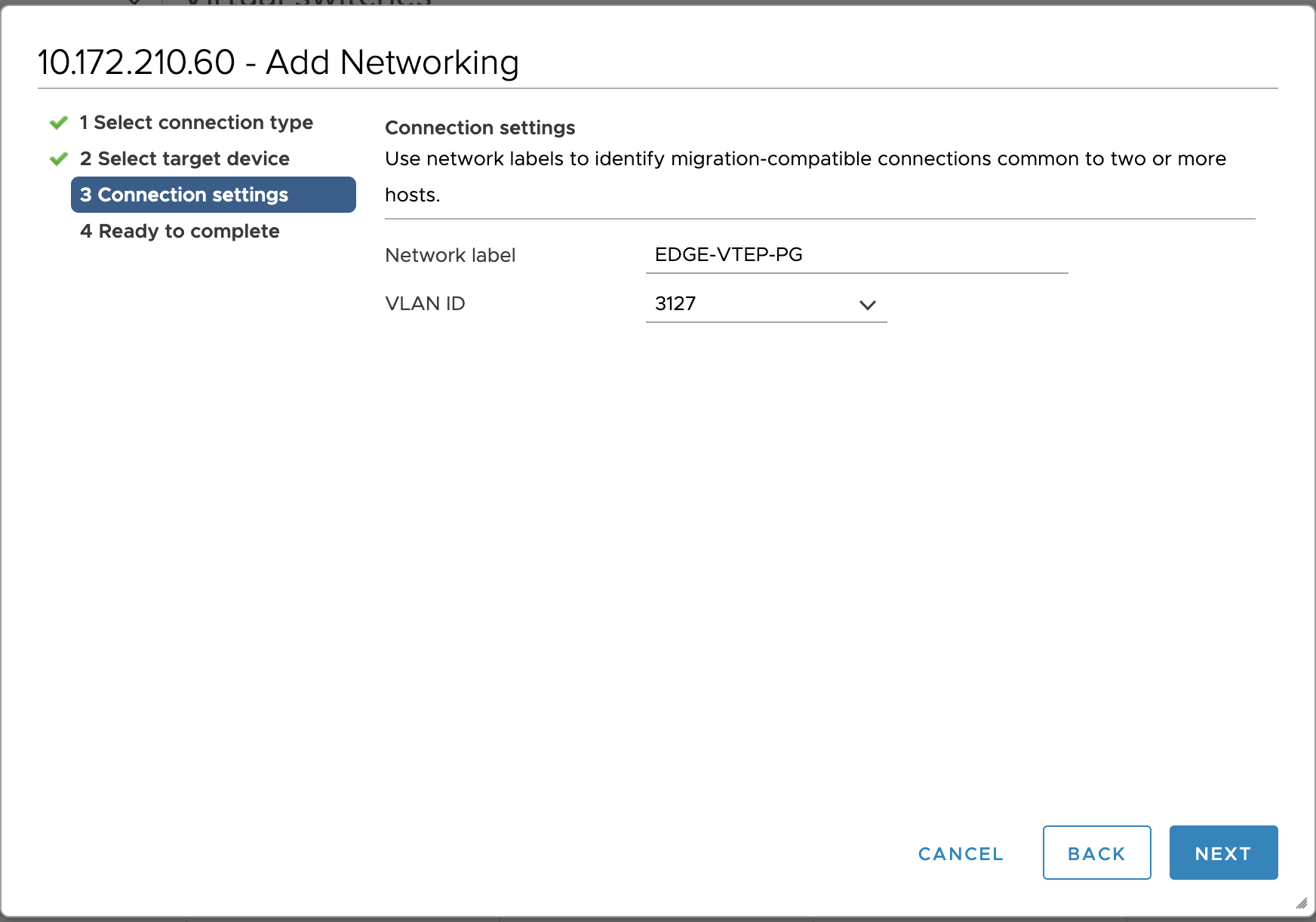
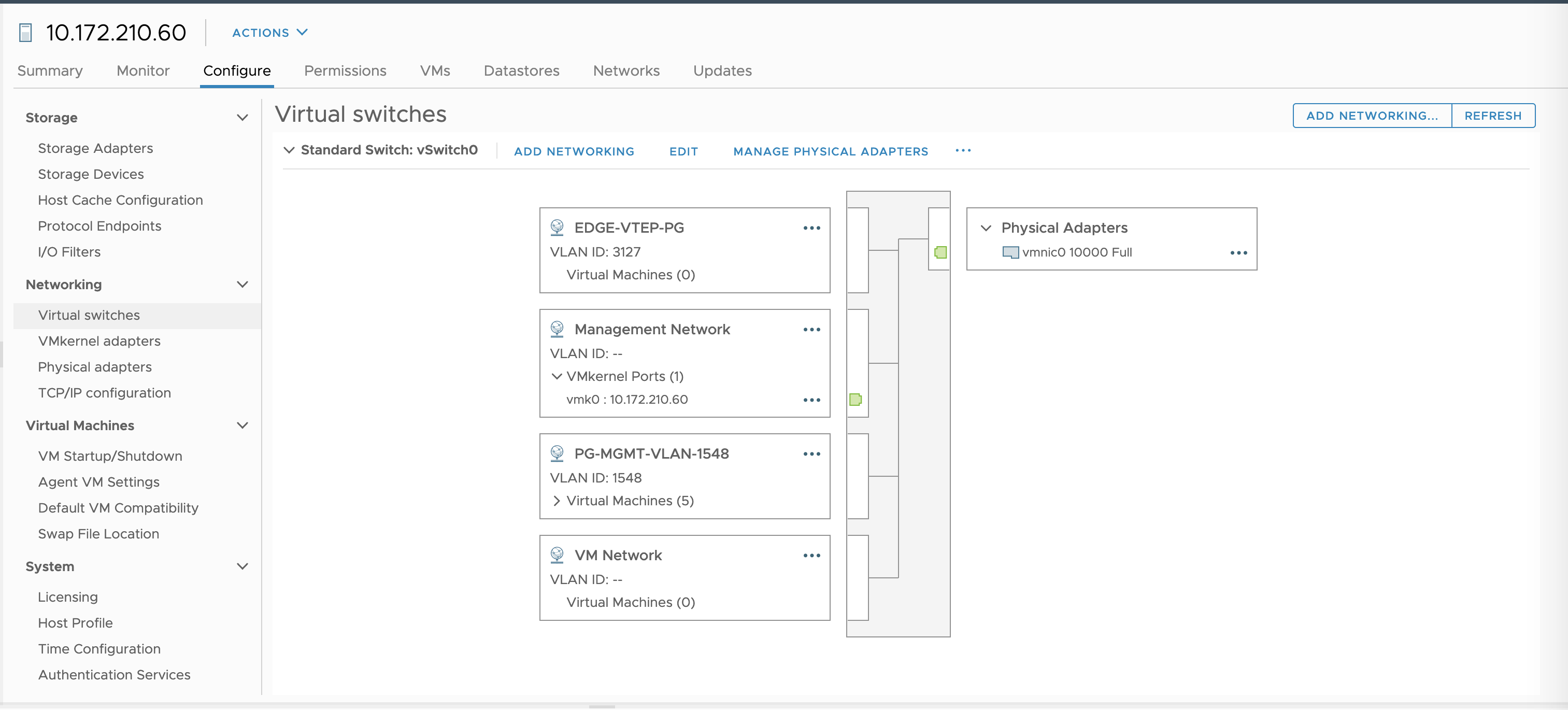
- Click Finish.
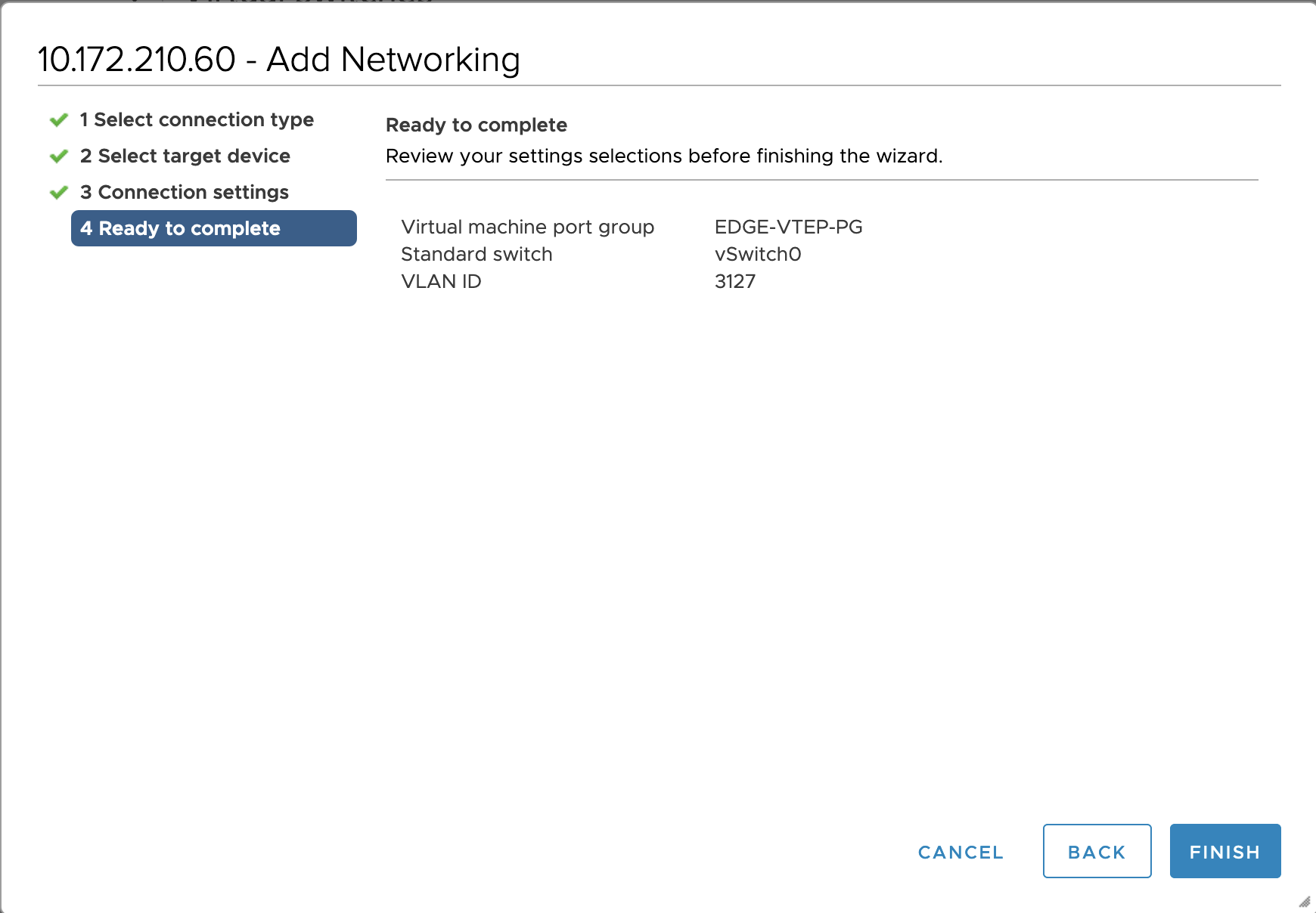
- Verify that you see the newly created port group.
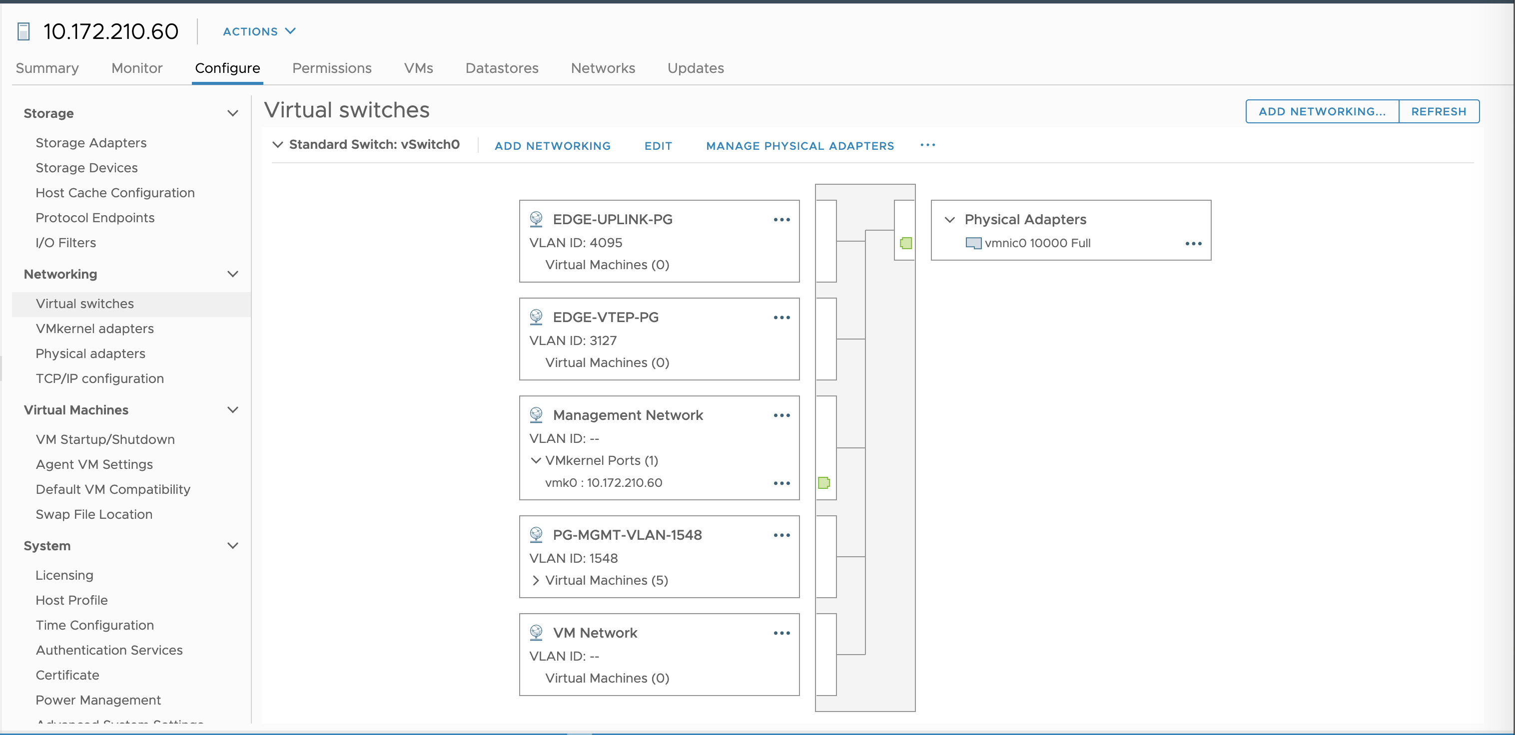
- Select Add Networking (upper right).
- Select the option Virtual Machine Port Group for a Standard Switch and click Next.
- Select the existing standard switch named
vSwitch0and click Next. - Enter a Network Label. For example,
EDGE-UPLINK-PG. - For the VLAN ID, select
All (4095)from the drop-down. - Click Finish.
- Verify that you see the newly created port group.
Set vSwitch0 with MTU at 9000
For each ESXi host in the MANAGEMENT-cluster, or each ESXi host in the vCenter cluster if you have not created separate Management and Compute clusters, you must enable the virtual switch with jumbo MTU, that is, set vSwitch0 with MTU=9000. If you do not do this, network overlay traffic will jam. The TEP interface for the NSX-T Edge Nodes must be connected to a port group that supports > 1600 bytes. The default is 1500.
- Select the Virtual Switch on each ESXi host in the MANAGEMENT-cluster, or each host in the vCenter cluster.
- Click Edit.
- For the MTU (bytes) setting, enter
9000.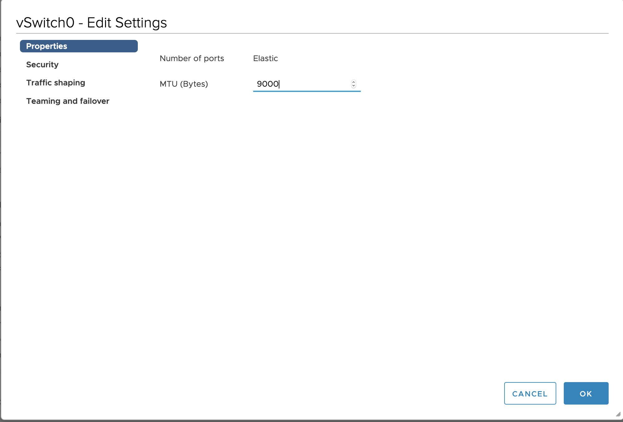
- Click OK to complete the operation.
Deploy NSX-T Edge Nodes
In this section you deploy two NSX-T Edge Nodes.
NSX-T Edge Nodes provide the bridge between the virtual network environment implemented using NSX-T and the physical network. Edge Nodes for Tanzu Kubernetes Grid Integrated Edition run load balancers for TKGI API traffic, Kubernetes load balancer services, and ingress controllers. See Load Balancers in Tanzu Kubernetes Grid Integrated Edition for more information.
In NSX-T, a load balancer is deployed on the Edge Nodes as a virtual server. The following virtual servers are required for Tanzu Kubernetes Grid Integrated Edition:
- 1 TCP Layer 4 virtual server for each Kubernetes service of type:
LoadBalancer - 2 Layer 7 global virtual servers for Kubernetes pod ingress resources (HTTP and HTTPS)
- 1 global virtual server for the TKGI API
The number of virtual servers that can be run depends on the size of the load balancer which depends on the size of the Edge Node. Tanzu Kubernetes Grid Integrated Edition supports the medium and large VM Edge Node form factor, as well as the bare metal Edge Node. The default size of the load balancer deployed by NSX-T for a Kubernetes cluster is small. The size of the load balancer can be customized using Network Profiles.
For this installation, we use the Large VM form factor for the Edge Node. See VMware Configuration Maximums for more information.
Install and Configure Edge Node 1
Deploy the Edge Node 1 VM using the NSX-T Manager interface.
-
From your browser, log in with admin privileges to NSX-T Manager at
https://NSX-MANAGER-IP-ADDRESS. -
In NSX-T Manager, go to System > Fabric > Nodes > Edge Transport Nodes.
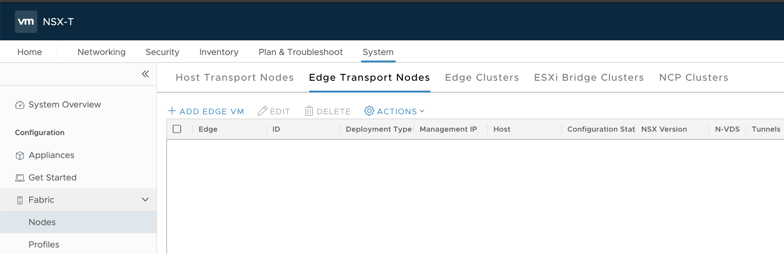
-
Click Add Edge VM.
-
Configure the Edge VM as follows:
- Name:
edge-node-1 - Host name/FQDN:
edge-node-1.lab.com - Form Factor:
Large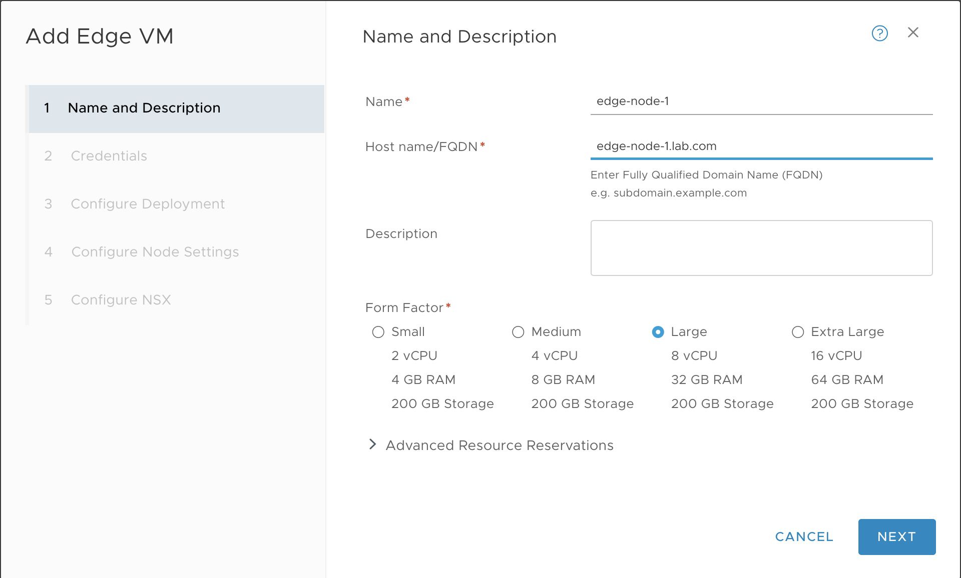
- Name:
-
Configure Credentials as follows:
- CLI User Name:
admin - CLI Password: Enter a strong password for the
adminuser that complies with the NSX-T requirements. - Enable SSH Login: Yes
- System Root Password: Enter a strong password for the
rootuser that complies with the NSX-T requirements. - Enable Root SSH Login: Yes
- Audit Credentials: Enter an
audituser name and password.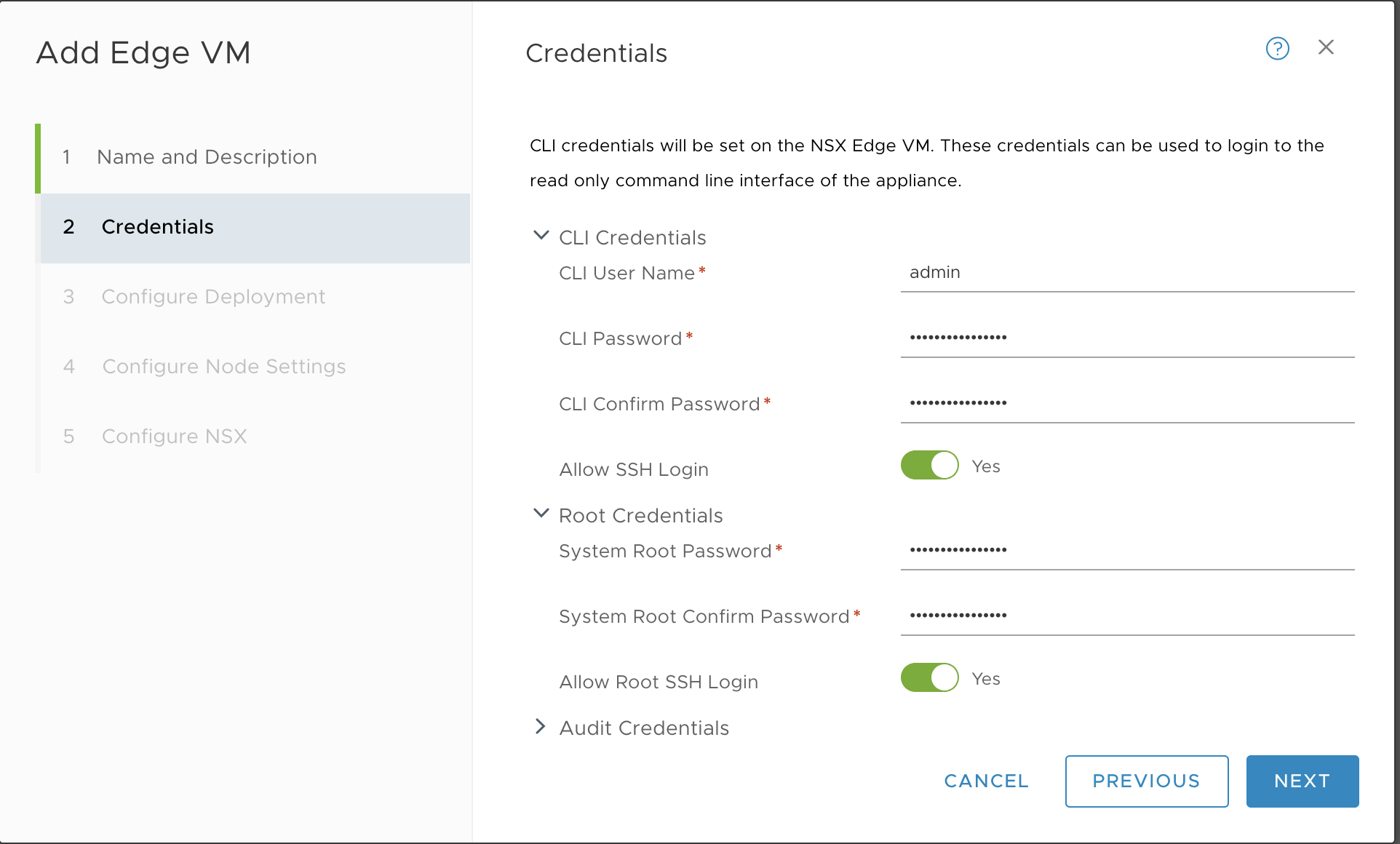
- CLI User Name:
-
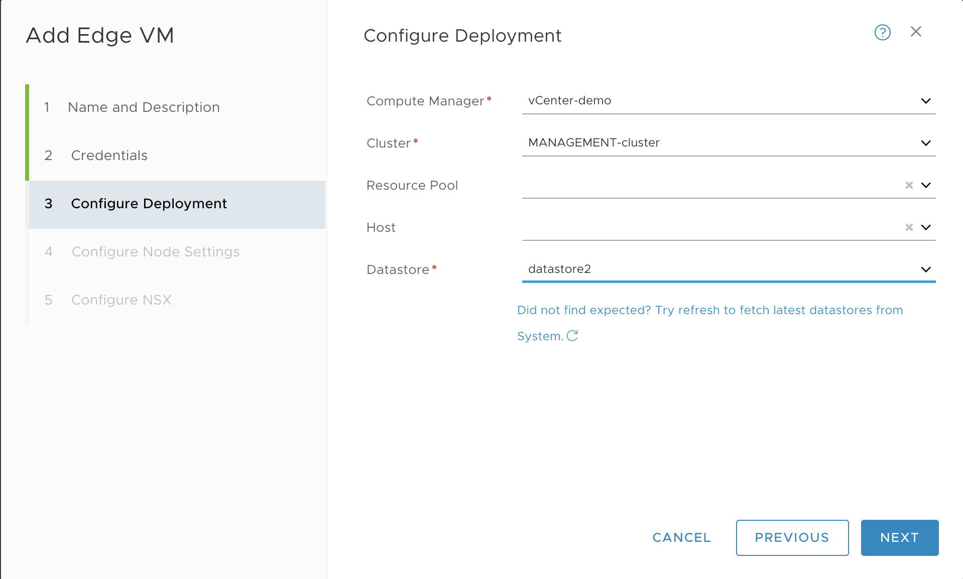
Configure the deployment as follows:
- Compute Manager: vCenter
- Cluster: MANAGEMENT-Cluster
- Datastore: Select the datastore
-
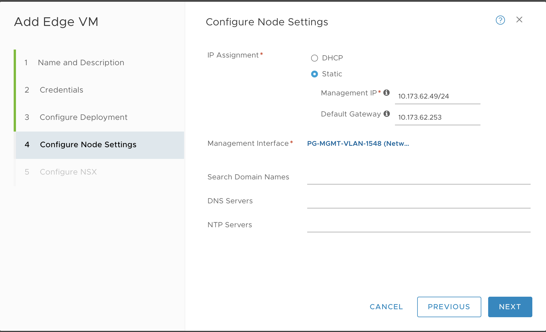
Configure the node settings as follows:
- IP Assignment: Static
- Management IP: 10.173.62.49/24, for example
- Default Gateway: 10.173.62.253, for example
- Management Interface: PG-MGMT-VLAN-1548, for example
Configure the N-VDS Switch or Switches for Edge Node 1
You can configure the N-VDS switch and transport zones for NSX Edge Node 2.
To configure N-VDS the switch and transport zones: - If you are using the default Transport Zones, use a single N-VDS switch. - If you are using custom Transport Zones, use a multiple N-VDS switches.
For more information, see Configuring NSX-T Data Center v3.1 Transport Zones and Edge Node Switches for TKGI.
Complete the Edge Node 1 Installation
-
Click Finish to complete the configuration. The installation begins.
-
In vCenter, use the Recent Tasks panel at the bottom of the page to verify that you see the Edge Node 1 VM being deployed.
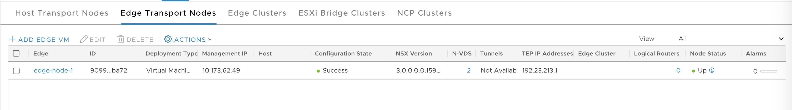
-
Once the process completes, verify the Edge Node 1 deployed successfully in NSX-T Manager.
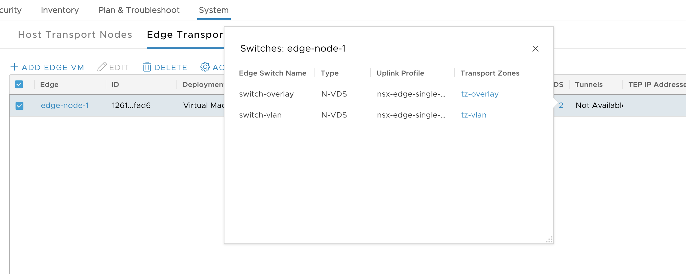
-
Click the N-VDS link and verify that you see the switch or switches.
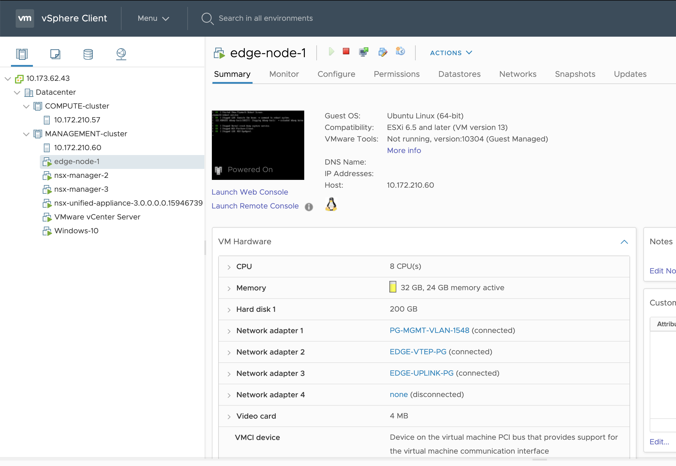
-
In vCenter verify that the Edge Node is created.
Install and Configure Edge Node 2
Deploy the Edge Node 2 VM using the NSX-T Manager interface.
-
In NSX-T Manager, go to System > Fabric > Nodes > Edge Transport Nodes.
-
Click Add Edge VM.
-
Configure the Edge VM as follows:
- Name:
edge-node-2 - Host name/FQDN:
edge-node-2.lab.com - Form Factor: Large
- Name:
-
Configure Credentials as follows:
- CLI User Name:
admin - CLI Password: Enter a strong password for the
adminuser that complies with the NSX-T requirements. - Enable SSH Login: Yes
- System Root Password: Enter a strong password for the
rootuser that complies with the NSX-T requirements. - Enable Root SSH Login: Yes
- Audit Credentials: Enter an
audituser name and password.
- CLI User Name:
-
Configure the deployment as follows:
- Compute Manager: vCenter
- Cluster: MANAGEMENT-Cluster
- Datastore: Select the datastore
-
Configure the node settings as follows:
- IP Assignment: Static
- Management IP: 10.173.62.58/24, for example
- Default Gateway: 10.173.62.253, , for example
- Management Interface: PG-MGMT-VLAN-1548, for example
Configure the N-VDS Switch or Switches for Edge Node 2
You can configure the N-VDS switch and transport zones for NSX Edge Node 2.
To configure N-VDS the switch and transport zones: - If you are using the default Transport Zones, use a single N-VDS switch. - If you are using custom Transport Zones, use a multiple N-VDS switches.
For more information, see Configuring NSX-T Data Center v3.1 Transport Zones and Edge Node Switches for TKGI.
Complete the Installation of Edge Node 2
-
Click Finish to complete the configuration. The installation begins.
-
In vCenter, use the Recent Tasks panel at the bottom of the page to verify that you see the Edge Node 1 VM being deployed.
-
Once the process completes, verify the Edge Node 2 deployed successfully in NSX-T Manager.
-
Click the N-VDS link and verify that you see the N-VDS switch or switches.
-
In vCenter verify that Edge Node 2 is created.
-
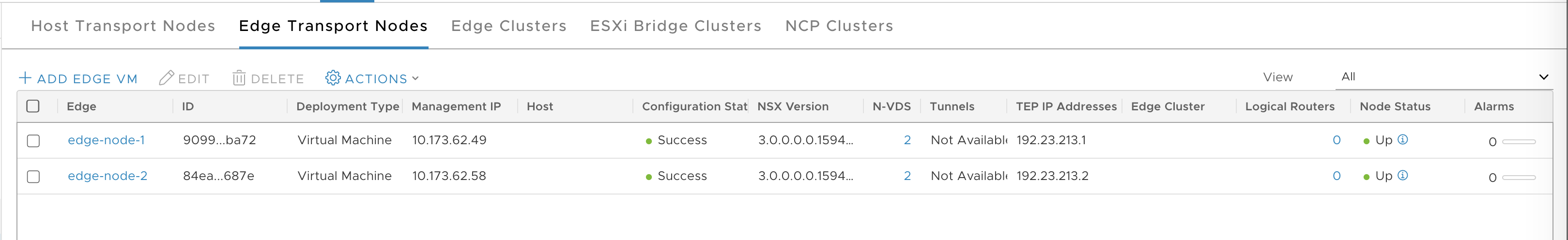
In NSX-T Manager, verify that you see both Edge Nodes.
Create Uplink Profile for ESXi Transport Node
To configure the TEP, we used the default profile named nsx-default-uplink-hostswitch-profile. However, because the TEP is on VLAN 3127, you must modify the uplink profile for the ESXi Transport Node (TN). NSX-T does not allow you to edit settings for the default uplink profile, so we create a new one.
-
Go to System > Fabric > Profiles > Uplink Profiles.
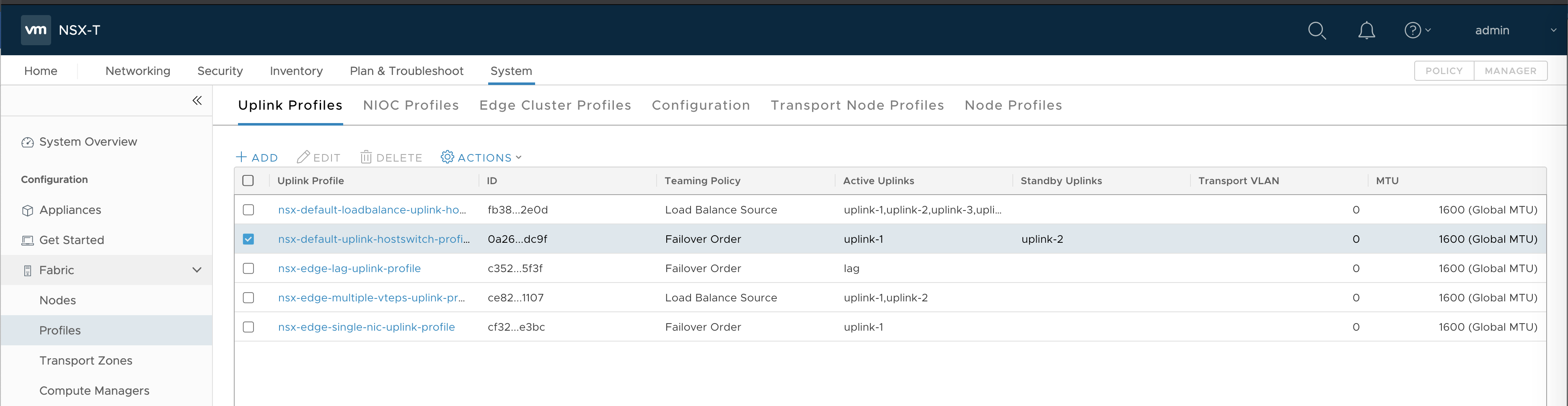
-
Click Add.
-
Configure the New Uplink Profile as follows:
- Name:
nsx-esxi-uplink-hostswitch-profile - Teaming Policy:
Failover Order - Active Uplinks:
uplink-1 - Transport vLAN:
3127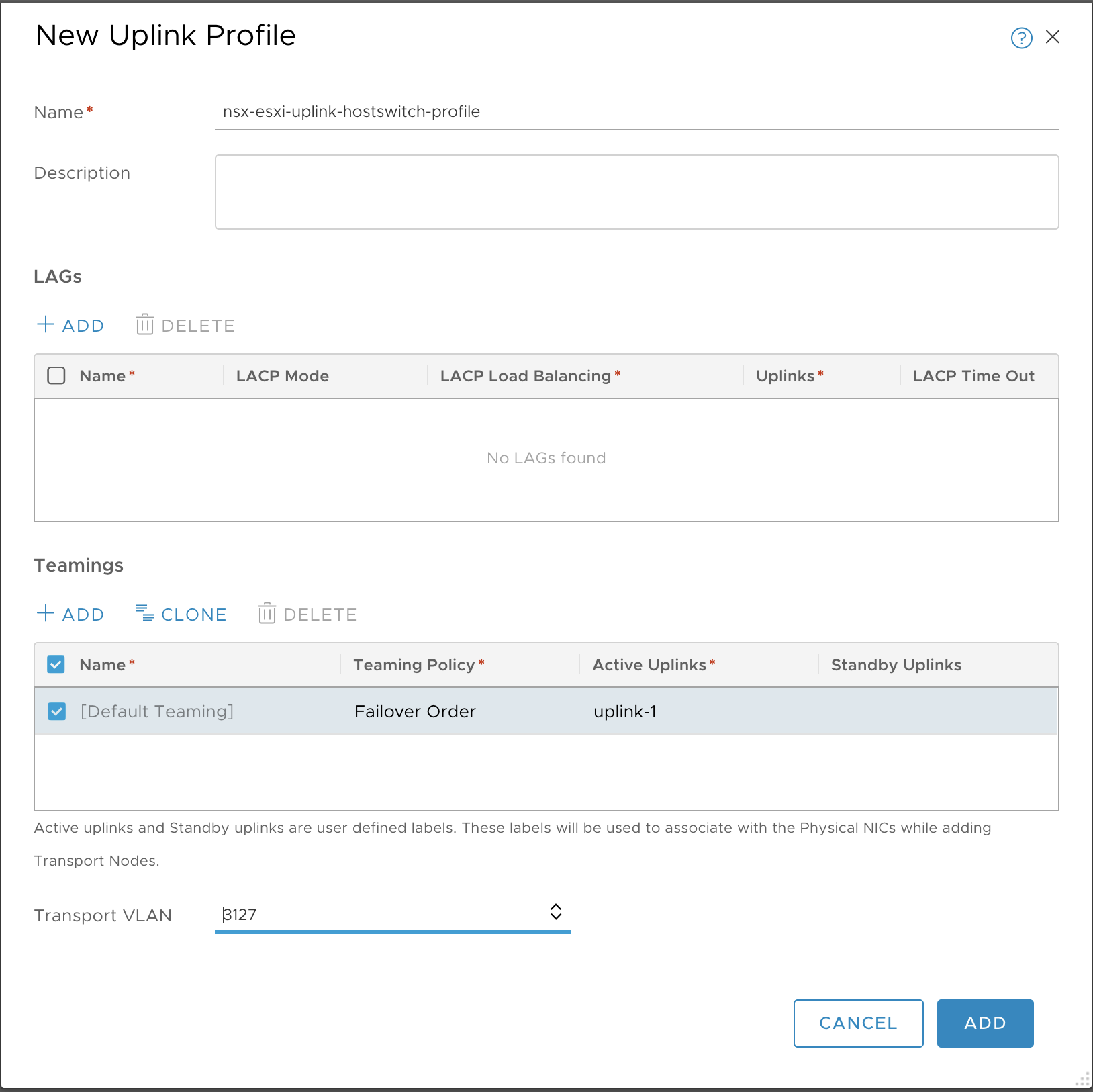
- Name:
-
Click Add.
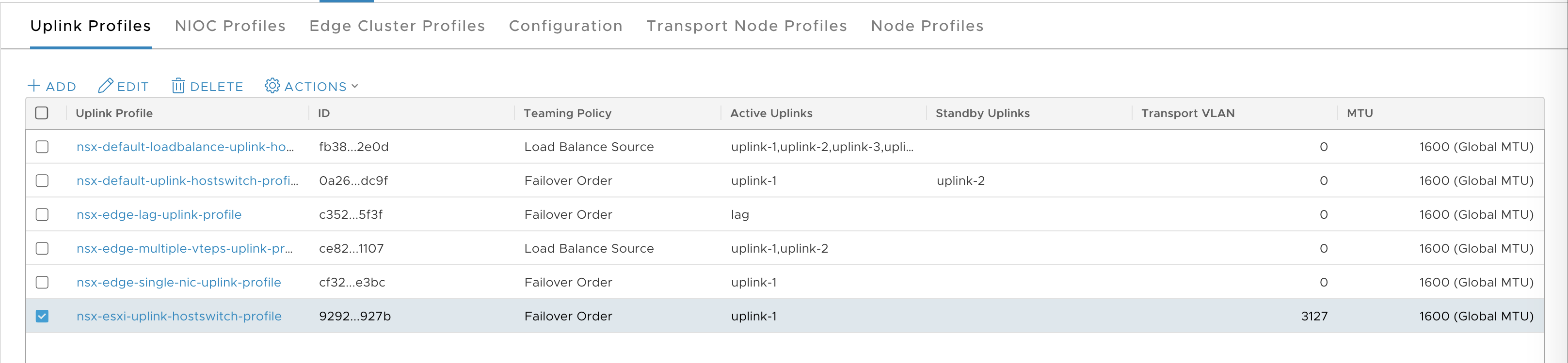
-
Verify that the Uplink Profile is created.
Deploy ESXi Host Transport Nodes Using VDS
Deploy each ESXi host in the COMPUTE-cluster as an ESXi host transport node (TN) in NSX-T. If you have not created a separate COMPUTE-cluster for ESXi hosts, deploy each ESXi host in the vSphere cluster as a host transport node in NSX-T.
-
Go to System > Fabric > Nodes > Host Transport Nodes.
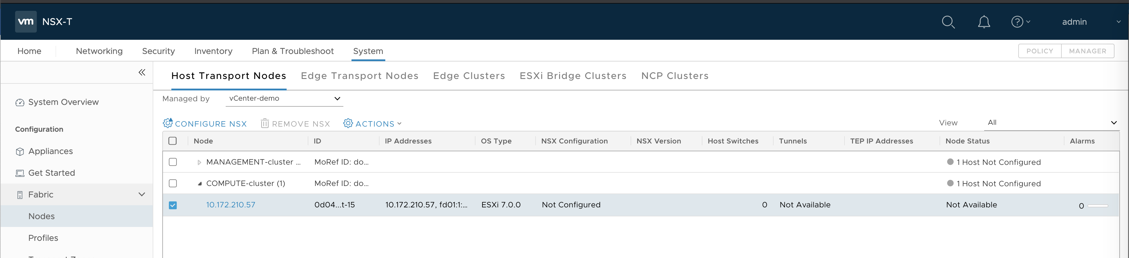
-
Expand the Compute Manager and select the ESXi host in the COMPUTE-cluster, or each ESXi host in the vSphere cluster.
-
Click Configure NSX.
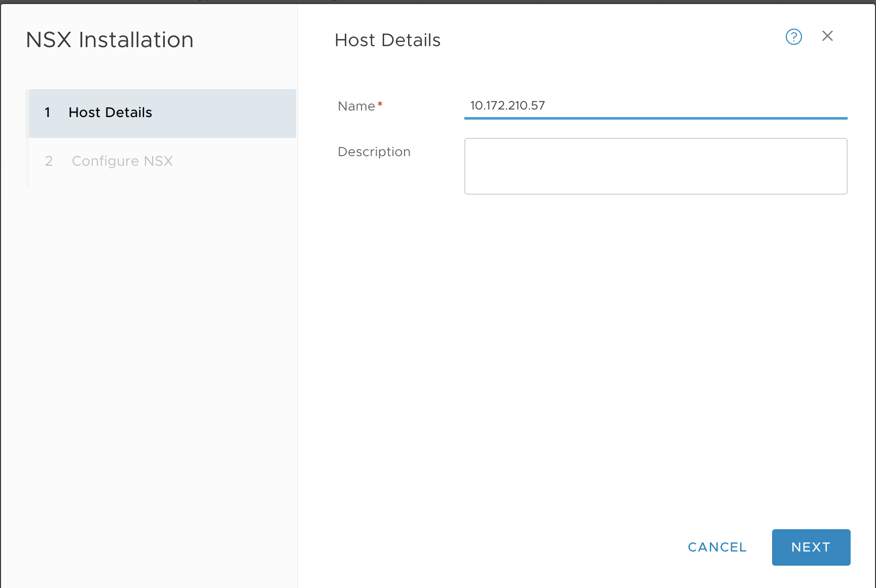
-
In the Host Details tab, enter a name. For example,
10.172.210.57. -
In the Configure NSX tab, configure the transport node as follows:
- Type:
VDS(do not select the N-VDS option) - Name:
switch-overlay(you must use the same switch name that was configured fortz-overlaytransport zone) - Transport Zone:
tz-overlay - NIOC Profile:
nsx-default-nioc-hostswitch-profile - Uplink Profile:
nsx-esxi-uplink-hostswitch-profile - LLDP Profile:
LLDP [Send Packet Disabled] - IP Assignment:
Use IP Pool - IP Pool:
TEP-IP-POOL - Teaming Policy Switch Mapping
- Uplinks:
uplink-1 - Physical NICs:
vmnic1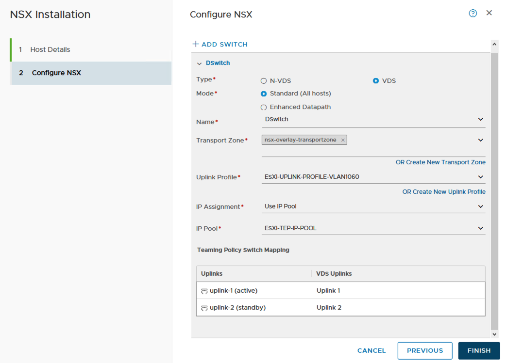
- Uplinks:
- Type:
-
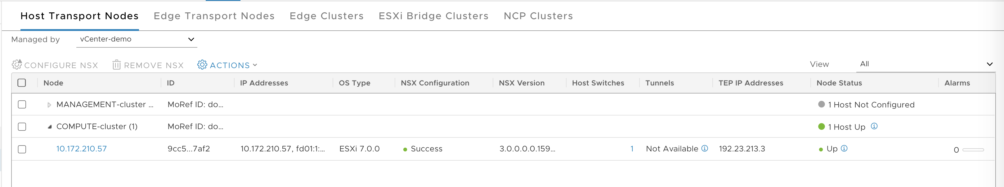
Click Finish.
-
Verify that the host TN is configured.
Verify TEP to TEP Connectivity
To avoid any overlay communication in the future due to MTU issue, test TEP to TEP connectivity and verify that it is working.
-
SSH to edge-node-1 and get the local TEP IP address. For example,
192.23.213.1. Use the commandget vtepsto get the IP. -
SSH to edge-node-2 and get the local TEP IP address, ushc as
192.23.213.2. Use the commandget vtepsto get the IP. -
SSH to the ESXi host and get the TEP IP address. For example,
192.23.213.3. Use the commandesxcfg-vmknic -lto get the IP. The interface will bevmk10and the NetStack will bevxlan. -
From each ESXi transport node, test the connections to each NSX-T Edge Node, for example:
# vmkping ++netstack=vxlan 192.23.213.1 -d -s 1572 -I vmk10: OK # vmkping ++netstack=vxlan 192.23.213.2 -d -s 1572 -I vmk10: OK-
Test the connection from NSX-T Edge Node 1 and Edge Node 2 to ESXi TN:
> vrf 0 > ping 192.23.213.1 size 1572 dfbit enable: OK -
Test the connection from NSX-T Edge Node 1 to NSX-T Edge Node 2:
> vrf 0
> ping 192.23.213.2 size 1572 dfbit enable: OK
-
Create NSX-T Edge Cluster
-
Go to System > Fabric > Nodes > Edge Clusters.
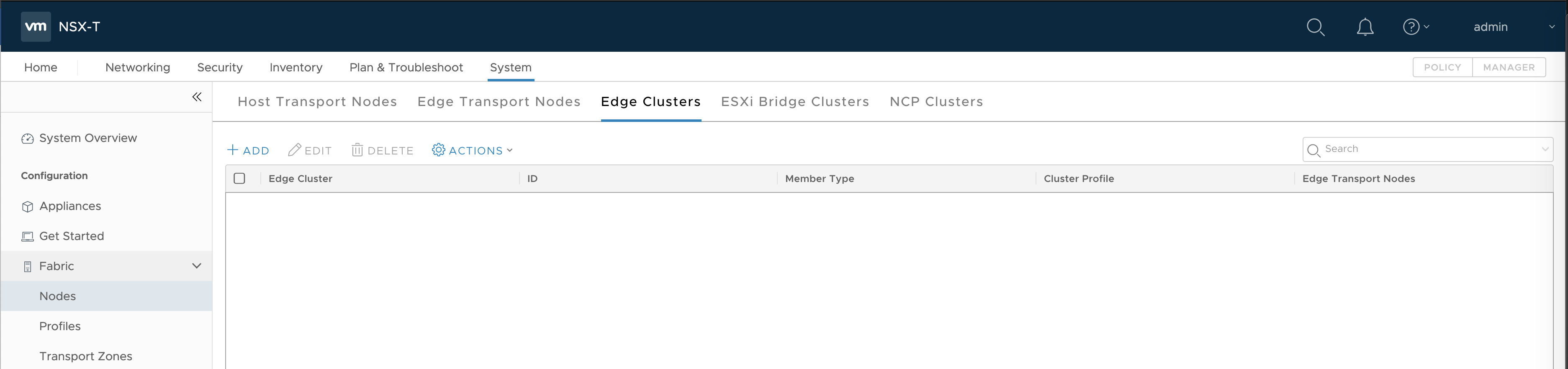
-
Click Add.
- Enter a name. For example,
edge-cluster-1. - Add members, including
edge-node-1andedge-node-2.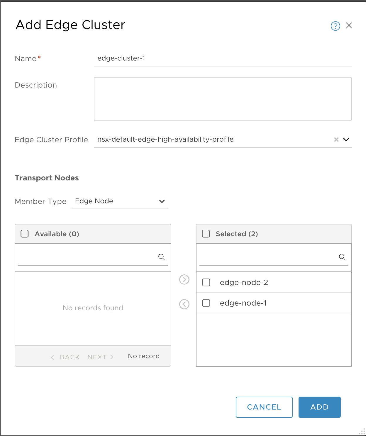
- Enter a name. For example,
-
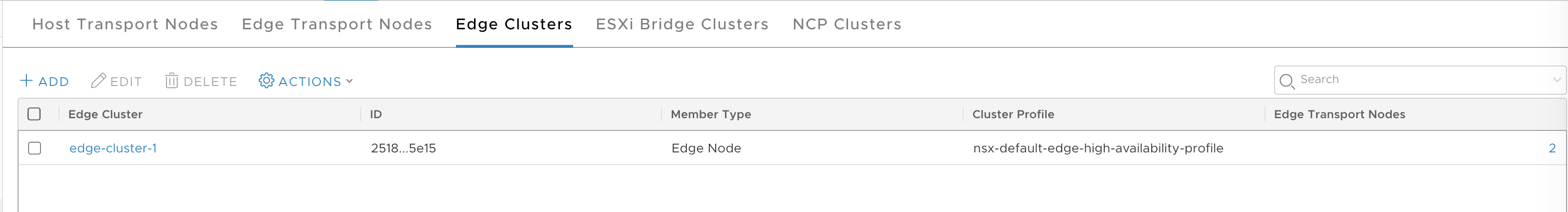
Click Add.
-
Verify.
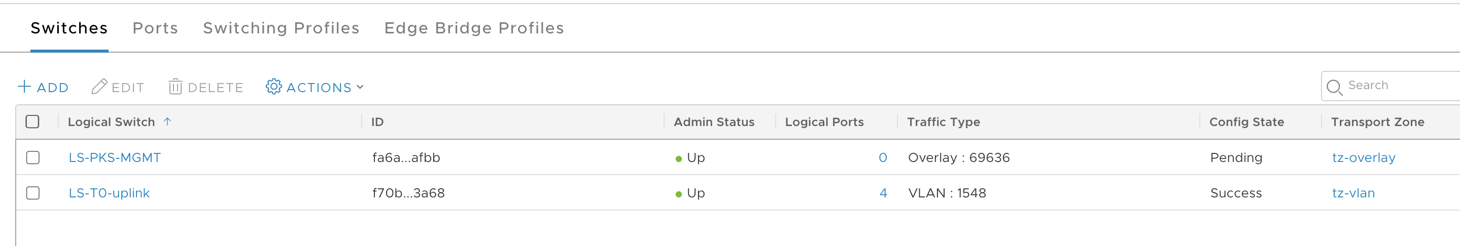
Create Uplink Logical Switch
Create an uplink Logical Switch to be used for the Tier-0 Router.
-
At upper-right, select the Manager tab.
-
Go to Networking > Logical Switches.
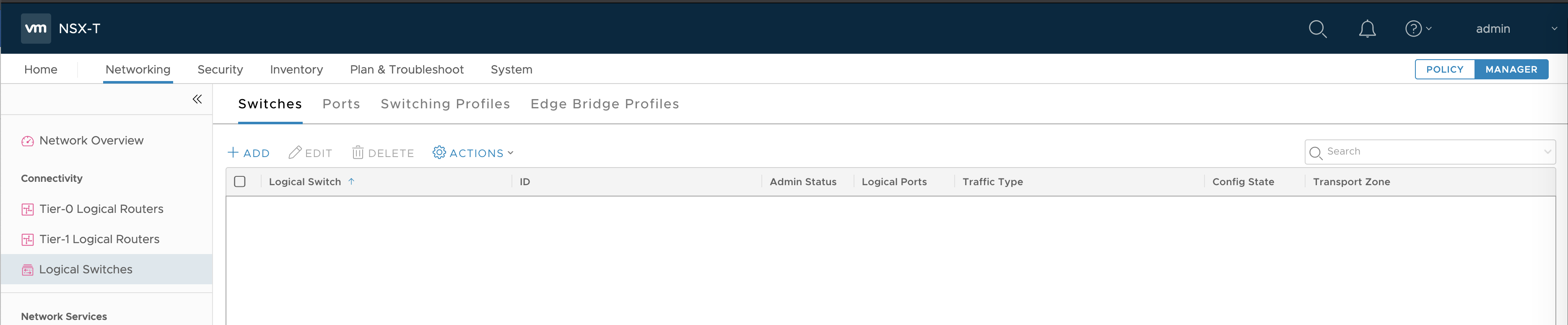
-
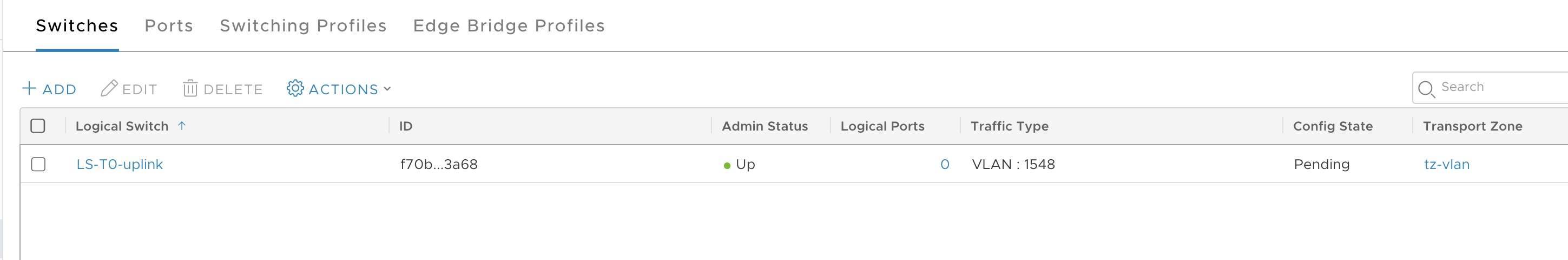
Click Add.
-
Configure the new logical switch as follows:
- Name:
LS-T0-uplink - Transport Zone:
tz-vlan - VLAN:
1548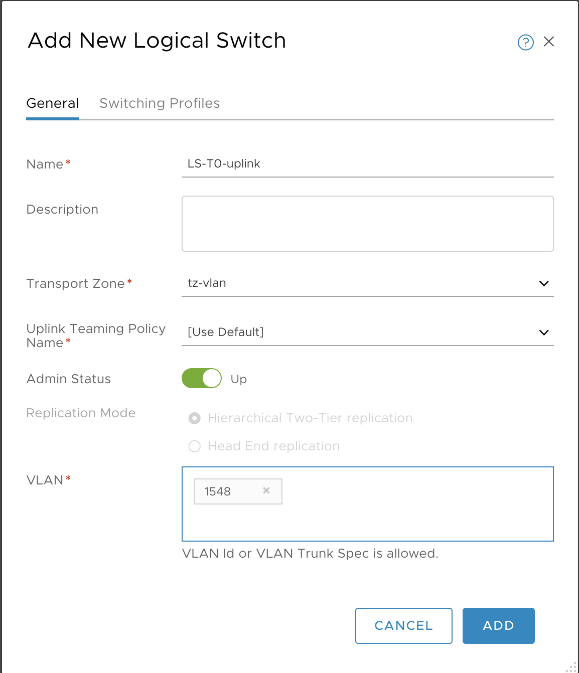
- Name:
-
Click Add.
-
Verify.
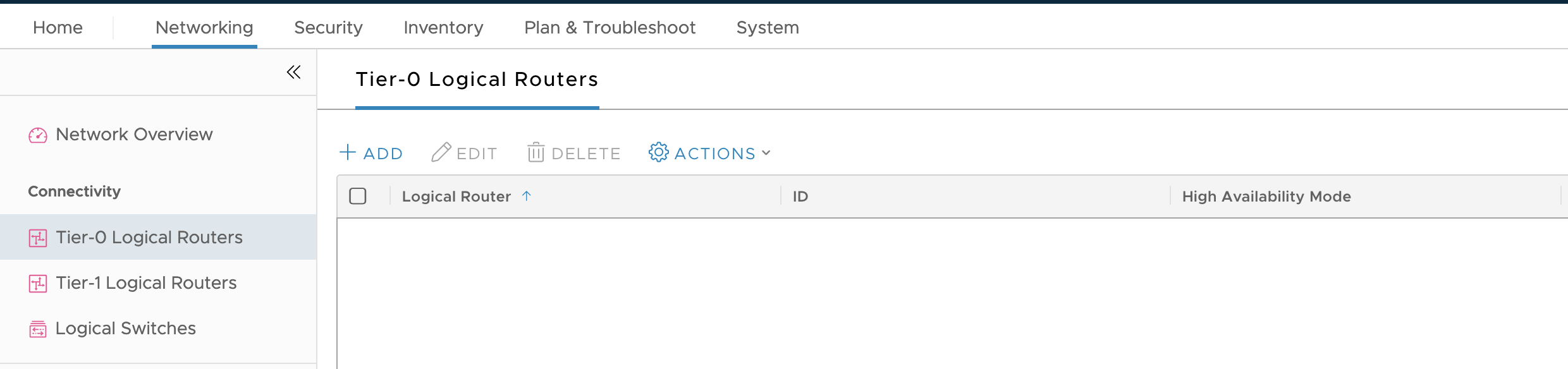
Create Tier-0 Router
-
Select Networking from the Manager tab.
-
Select Tier-0 Logical Router.
-
Click Add.
-
Configure the new Tier-0 Router as follows:
- Name:
T0-router - Edge Cluster:
edge-cluster-1 - HA mode: Either
Active-ActiveorActive-Standby - Failover mode:
Non-Preemptive
Note: Configuring Failover mode is optional if HA mode is configured as
Active-Active. For more information on NSX-T HA mode configuration, see Add a Tier-0 Gateway in the VMware NSX-T Data Center documentation.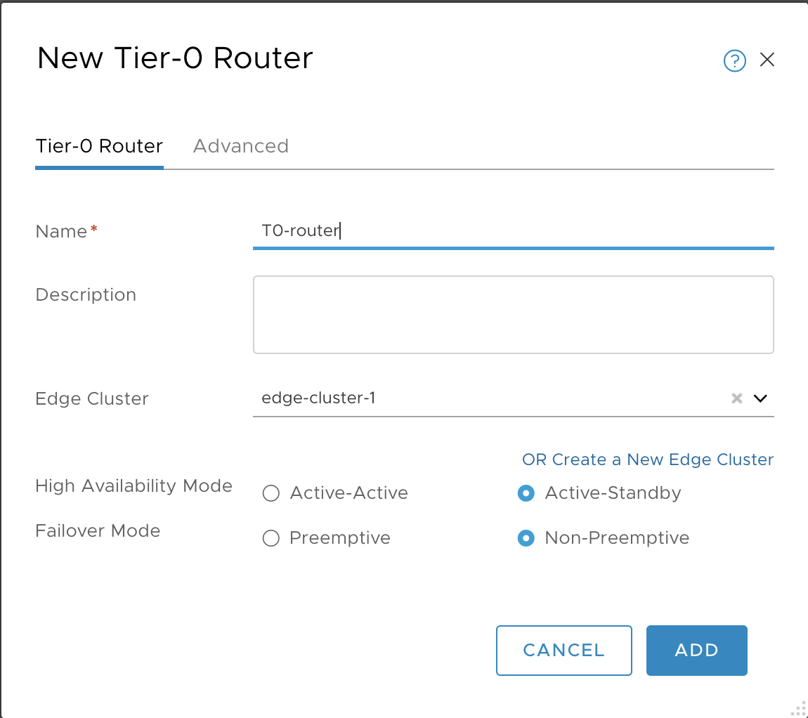
- Name:
-
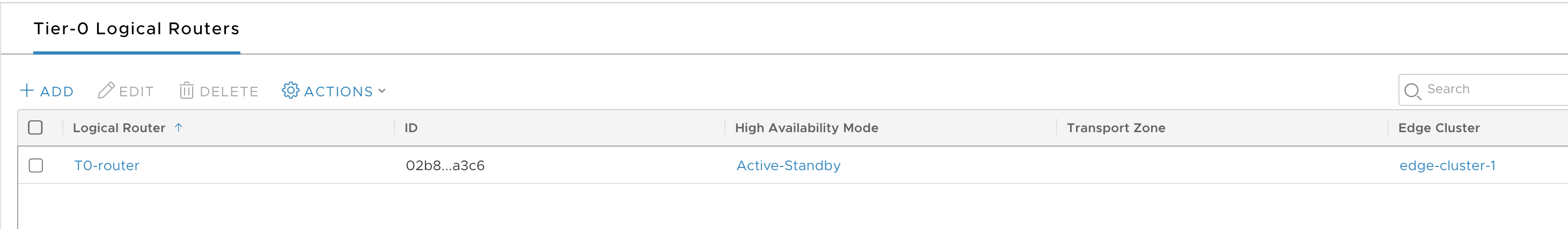
Click Save and verify.
-
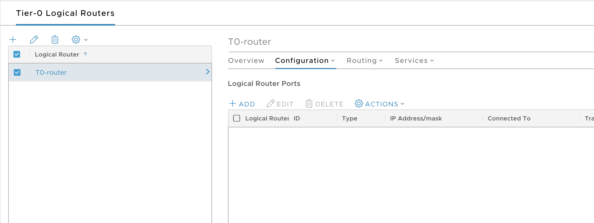
Select the T0 router.
-
Select Configuration > Router Ports.
-
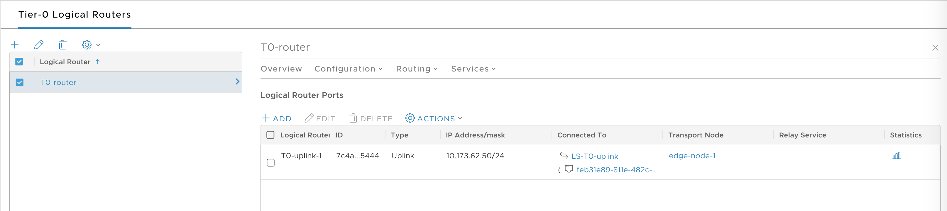
Click Add.
-
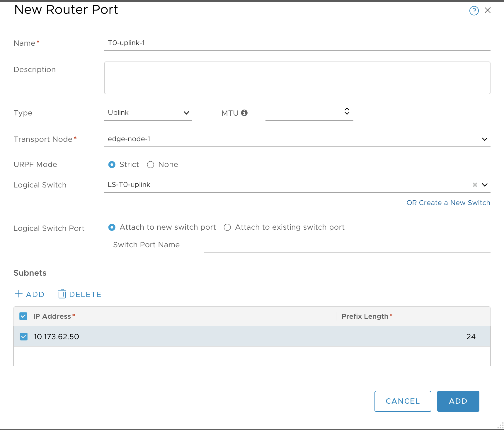
Configure a new router port as follows:
- Name: T0-uplink-1
- Type: uplink
- Transport Node: edge-node-1
- Logical Switch: LS-T0-uplink
- Logical Switch Port: Attach to a new switch port
- Subnet: 10.173.62.50 / 24
-
Click Add and verify.
-
Select the T0 router.
-
Select Configuration > Router Ports.
-
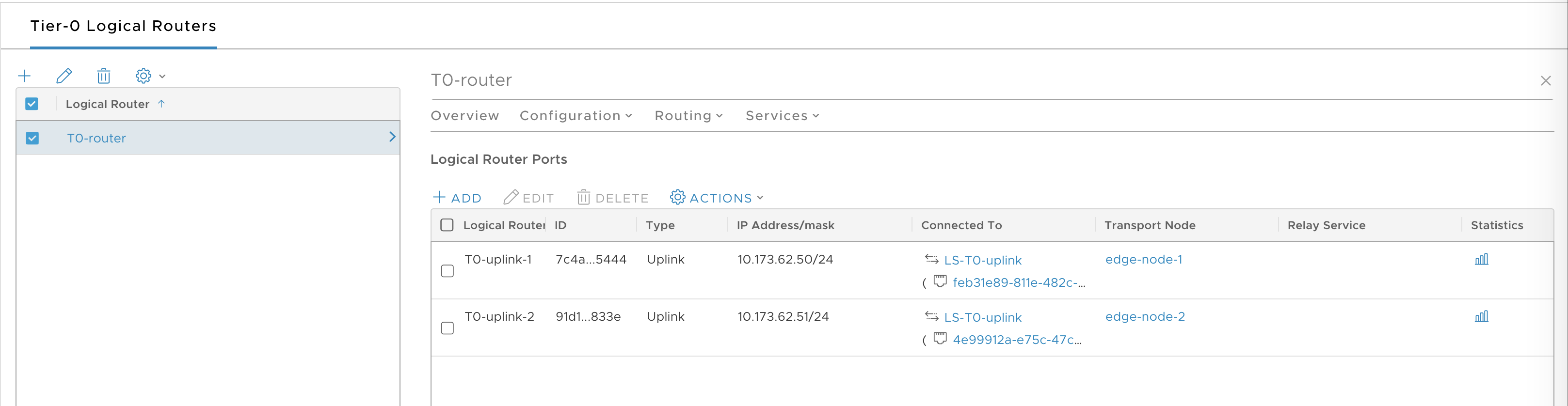
Add a second uplink by creating a second router port for edge-node-2:
- Name: T0-uplink-1
- Type: uplink
- Transport Node: edge-node-2
- Logical Switch: LS-T0-uplink
- Logical Switch Port: Attach to a new switch port
- Subnet: 10.173.62.51 / 24
-
Once completed, verify that you have two connected router ports.
Configure and Test the Tier-0 Router
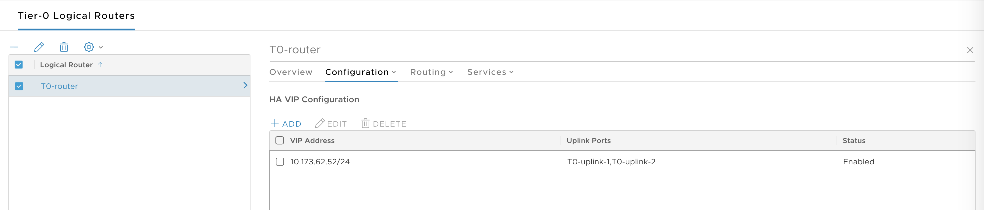
Create an HA VIP for the T0 router, and a default route for the T0 router. Then test the T0 router.
-
Select the Tier-0 Router you created.
-
Select Configuration > HA VIP.
-
Click Add.
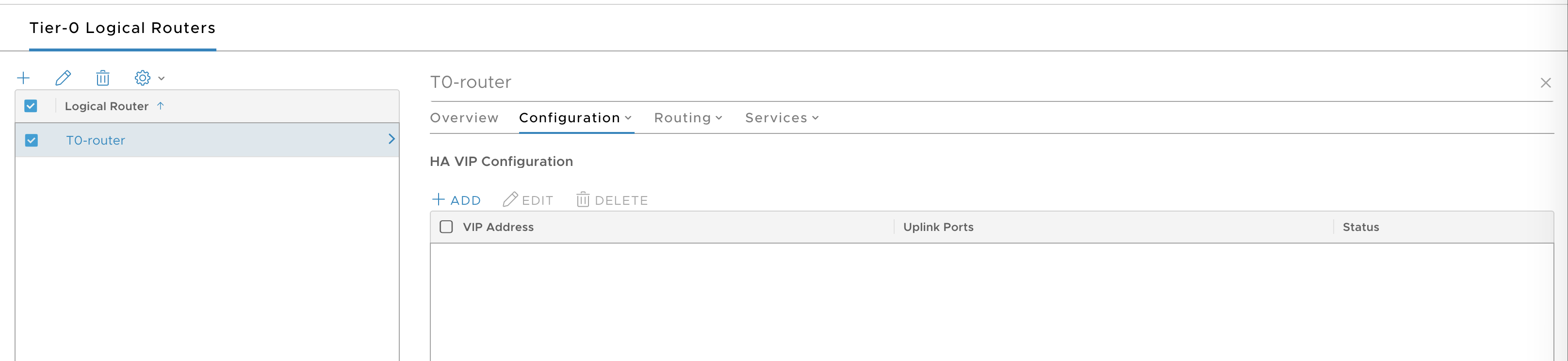
-
Configure the HA VIP as follows:
- VIP address: 10.173.62.52/24, for example
- Uplink ports: T0-uplink-1 and T0-uplink-2
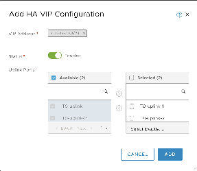
-
Click Add and verify.
-
Select Routing > Static Routes.
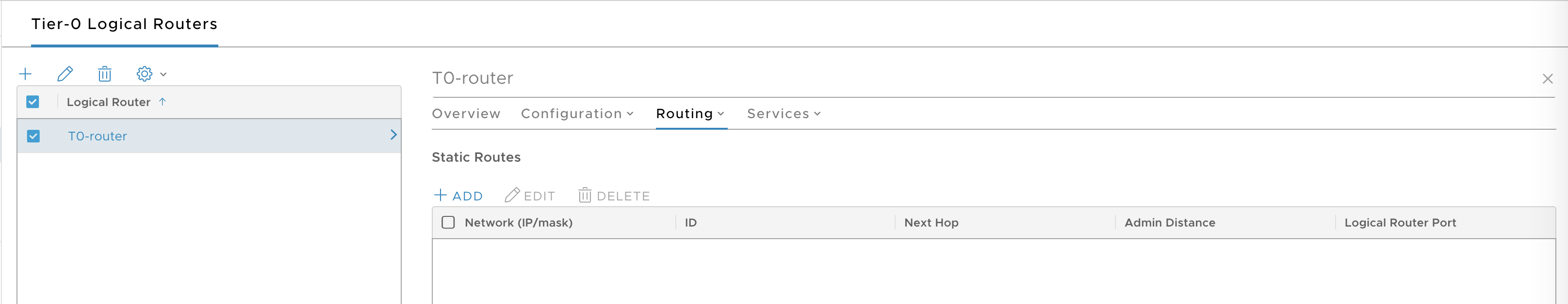
-
Click Add.
- Network:
0.0.0.0/0 - Next Hop:
10.173.62.253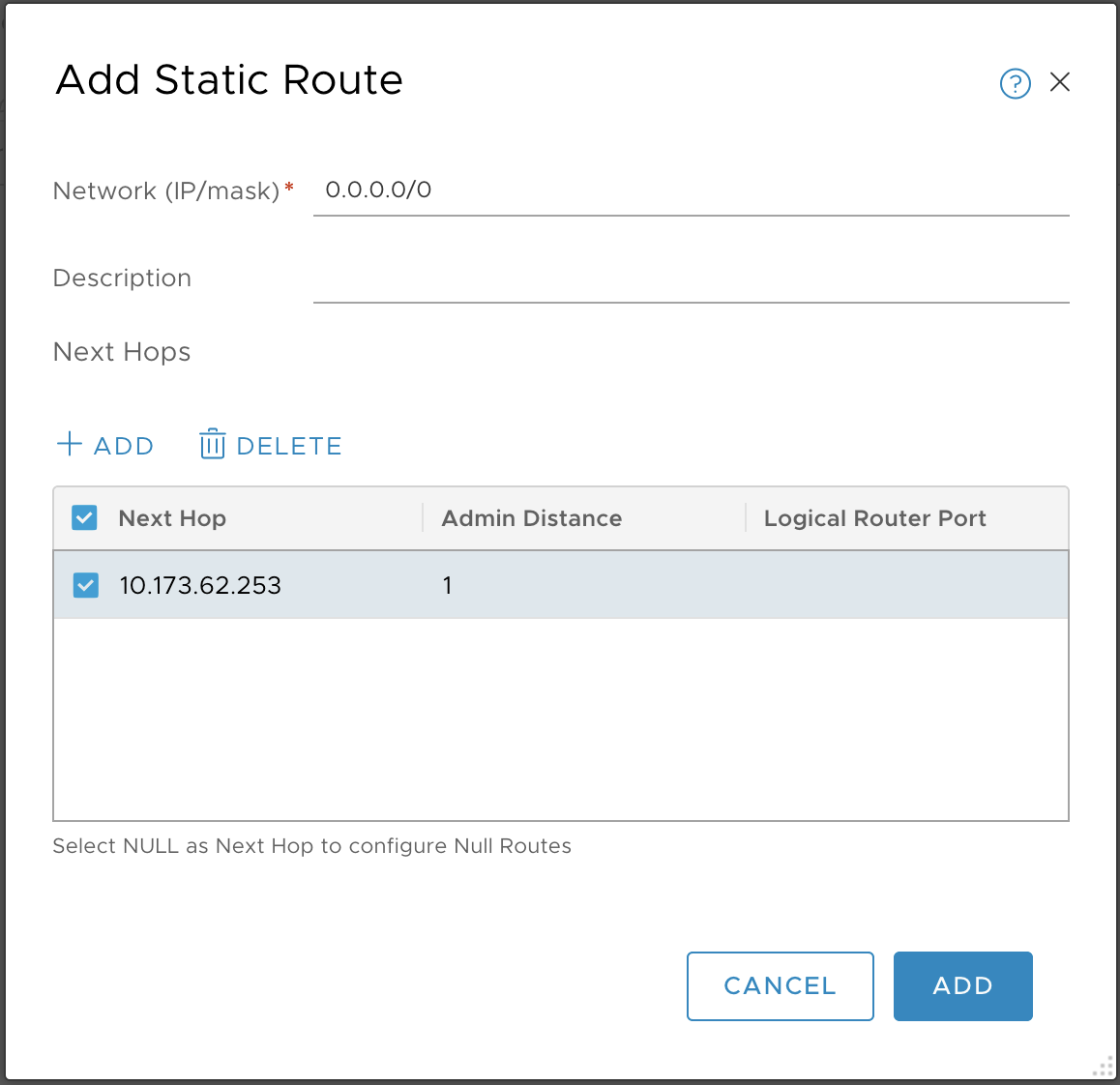
- Network:
-
Click Add and verify.
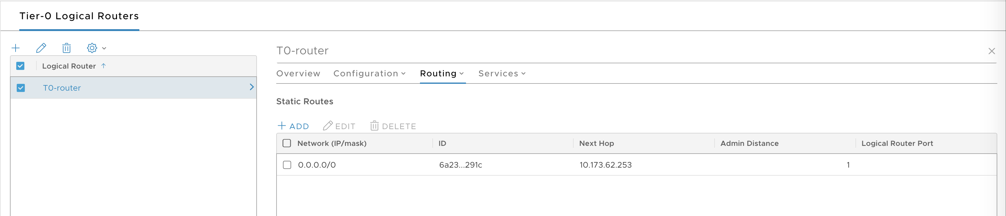
-
Verify the Tier 0 router by making sure the T0 uplinks and HA VIP are reachable from your laptop.
For example:
> ping 10.173.62.50
PING 10.173.62.50 (10.173.62.50): 56 data bytes
Request timeout for icmp_seq 0
64 bytes from 10.173.62.50: icmp_seq=1 ttl=58 time=71.741 ms
64 bytes from 10.173.62.50: icmp_seq=0 ttl=58 time=1074.679 ms

> ping 10.173.62.51
PING 10.173.62.51 (10.173.62.51): 56 data bytes
Request timeout for icmp_seq 0
64 bytes from 10.173.62.51: icmp_seq=0 ttl=58 time=1156.627 ms
64 bytes from 10.173.62.51: icmp_seq=1 ttl=58 time=151.413 ms

> ping 10.173.62.52
PING 10.173.62.52 (10.173.62.52): 56 data bytes
64 bytes from 10.173.62.52: icmp_seq=0 ttl=58 time=6.864 ms
64 bytes from 10.173.62.52: icmp_seq=1 ttl=58 time=7.776 ms
Create IP Blocks and Pool for Compute Plane
TKGI requires a Floating IP Pool for NSX-T load balancer assignment and the following two IP blocks for Kubernetes pods and nodes:
- TKGI-POD-IP-BLOCK: 172.16.0.0/16
-
TKGI-NODE-IP-BLOCK: 172.23.0.0/16
-
In the Manager interface, go to Networking > IP Address Pools > IP Block.
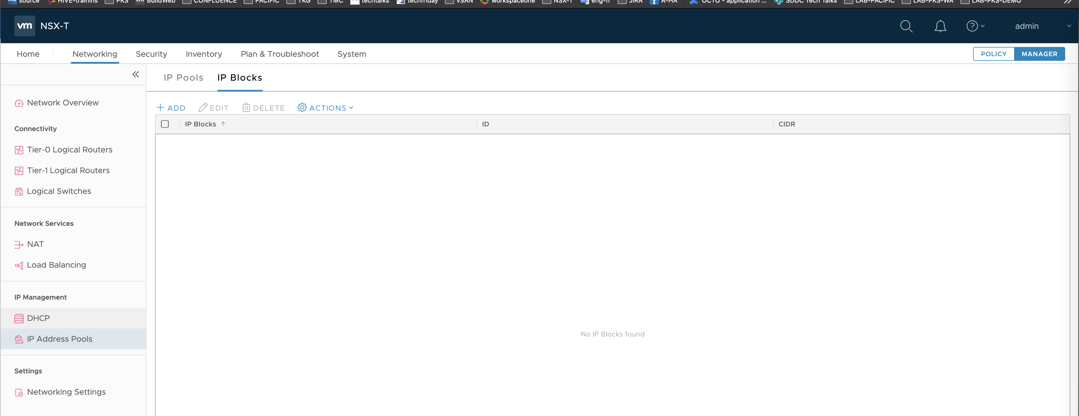
-
Click Add.
-
Configure the Pod IP Block as follows:
- Name: TKGI-POD-IP-BLOCK
- CIDR: 172.16.0.0/16
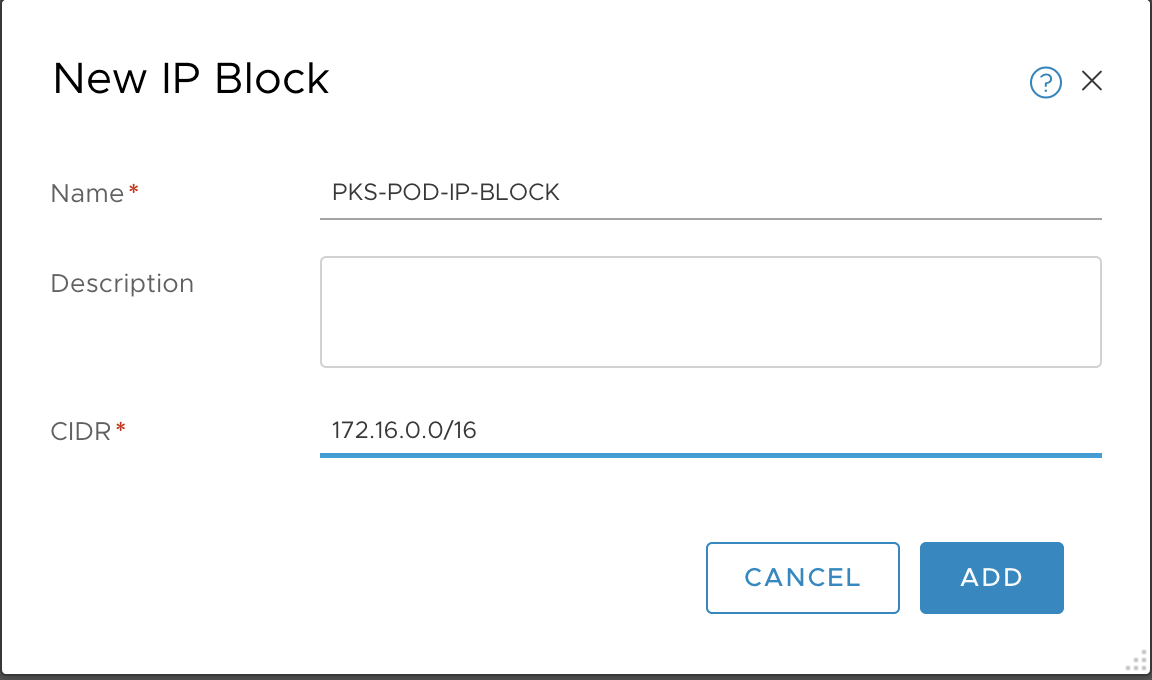
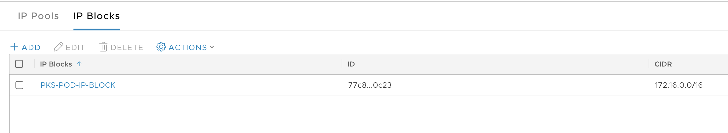
-
Click Add and verify.
-
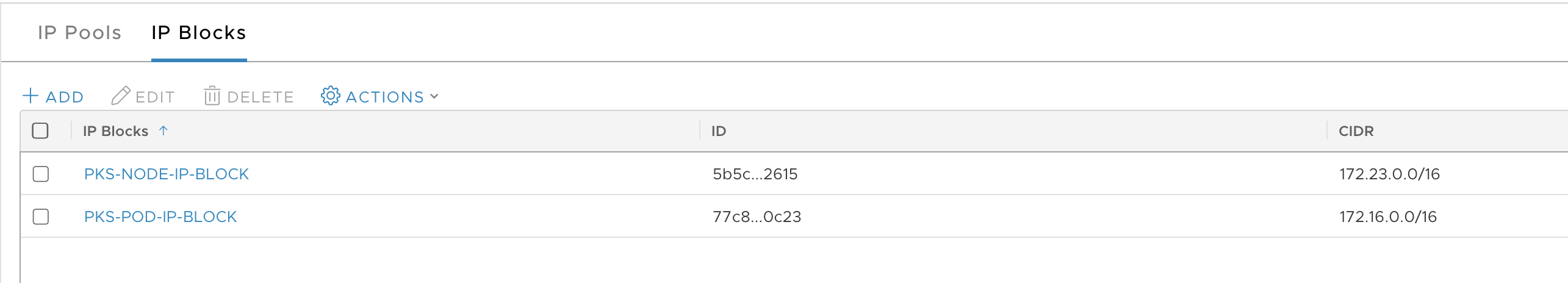
Repeat same operation for the Node IP Block.
- Name: TKGI-NODE-IP-BLOCK
- CIDR: 172.23.0.0/16
-
Click Add and verify.
-
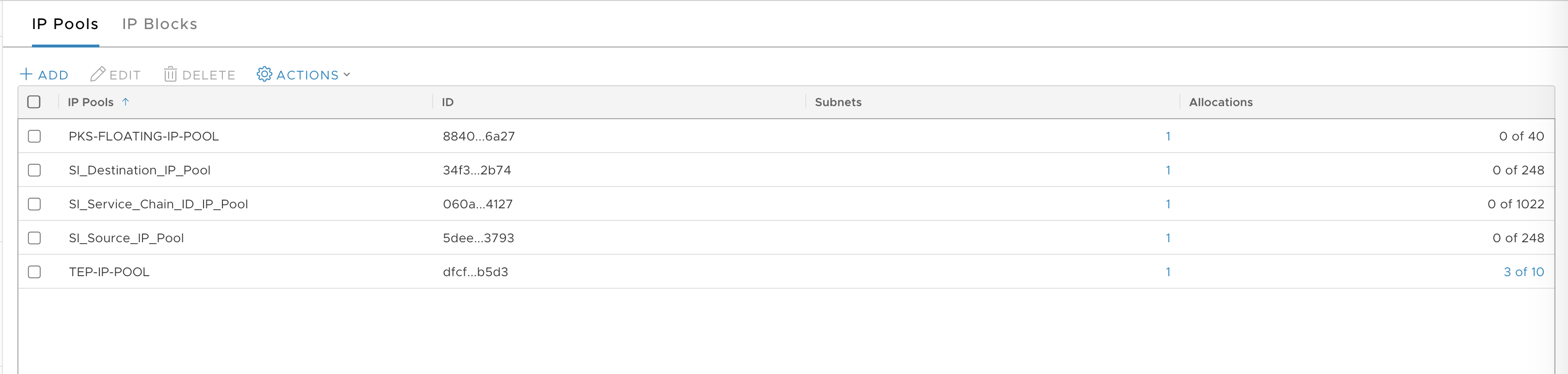
Select IP Pools tab.
-
Click Add.
-
Configure the IP pool as follows:
- Name: TKGI-FLOATING-IP-POOL
- IP ranges: 10.173.62.111 - 10.173.62.150
- CIDR: 10.173.62.0/24
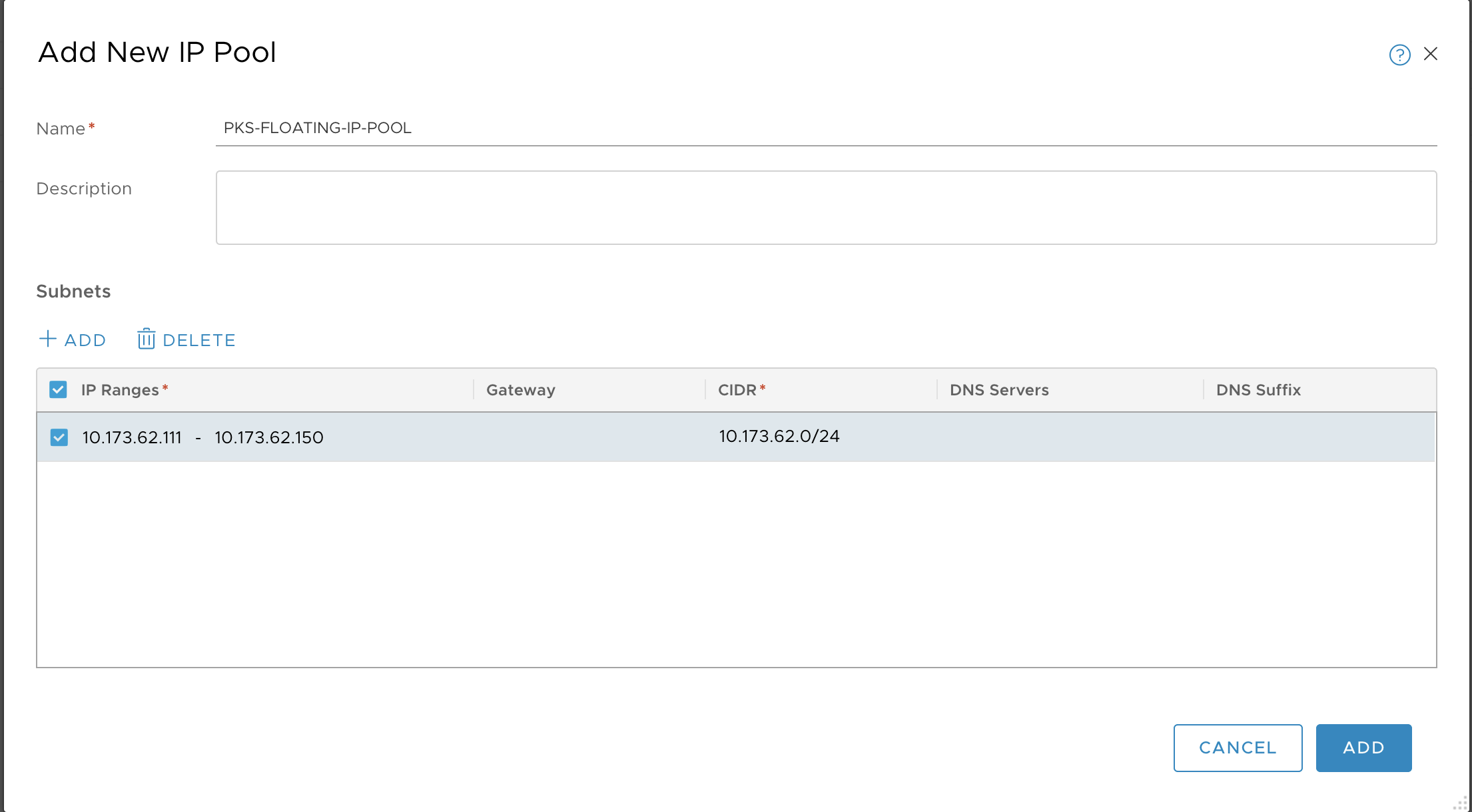
-
Click Add and verify.
Create Management Plane
Networking for the TKGI Management Plane consists of a Tier-1 Router and Switch with NAT Rules for the Management Plane VMs.
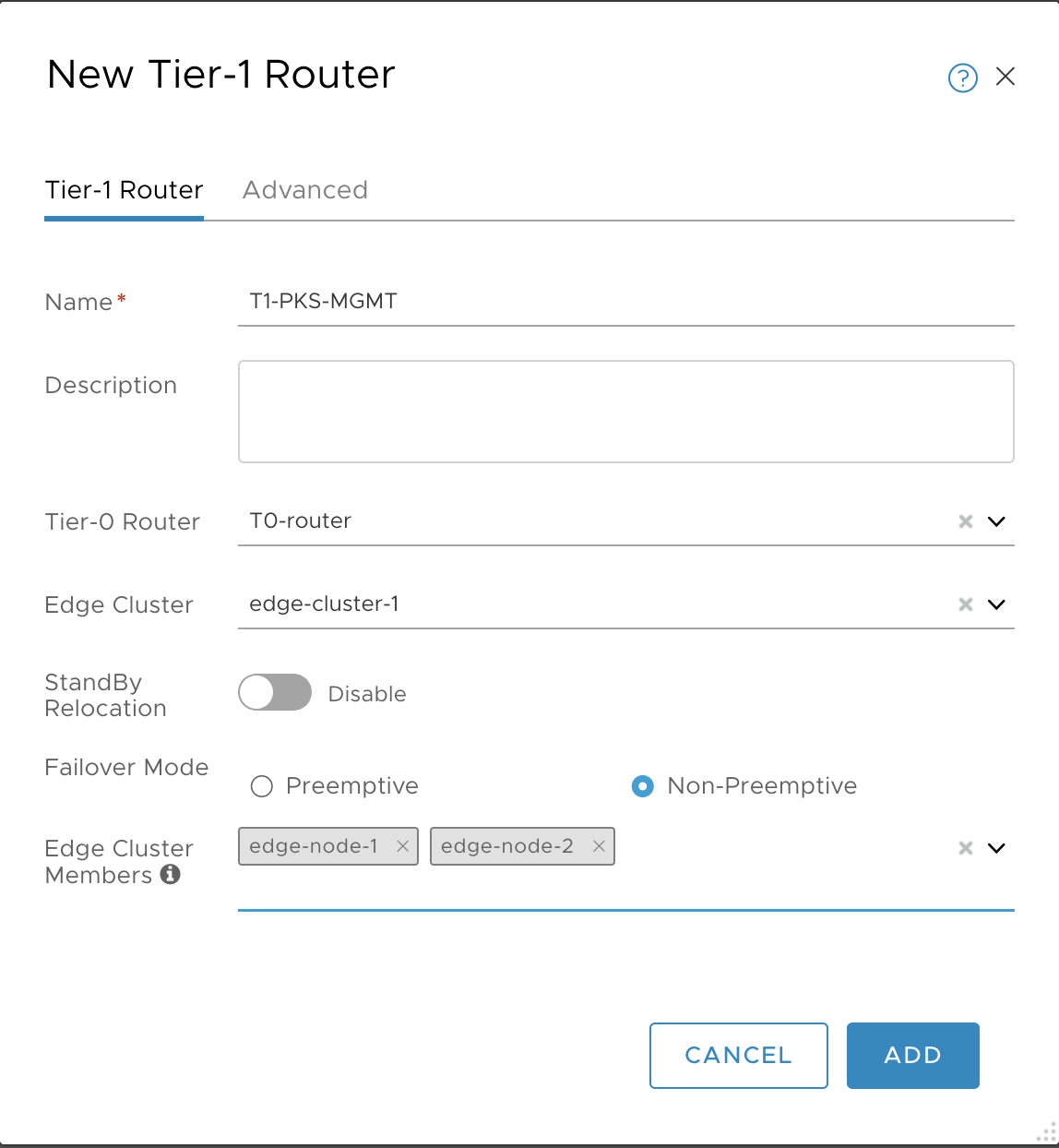
Create Tier-1 Router and Switch
Create Tier-1 Logical Switch and Router for TKGI Management Plane VMs. Complete the configuration by enabling Route Advertisement on the T1 router.
-
In the NSX Management console, navigate to Networking > Logical Switches.
-
Click Add.
-
Create the LS for TKGI Management plane VMs:
- Name: LS-TKGI-MGMT
- Transport Zone: tz-overlay
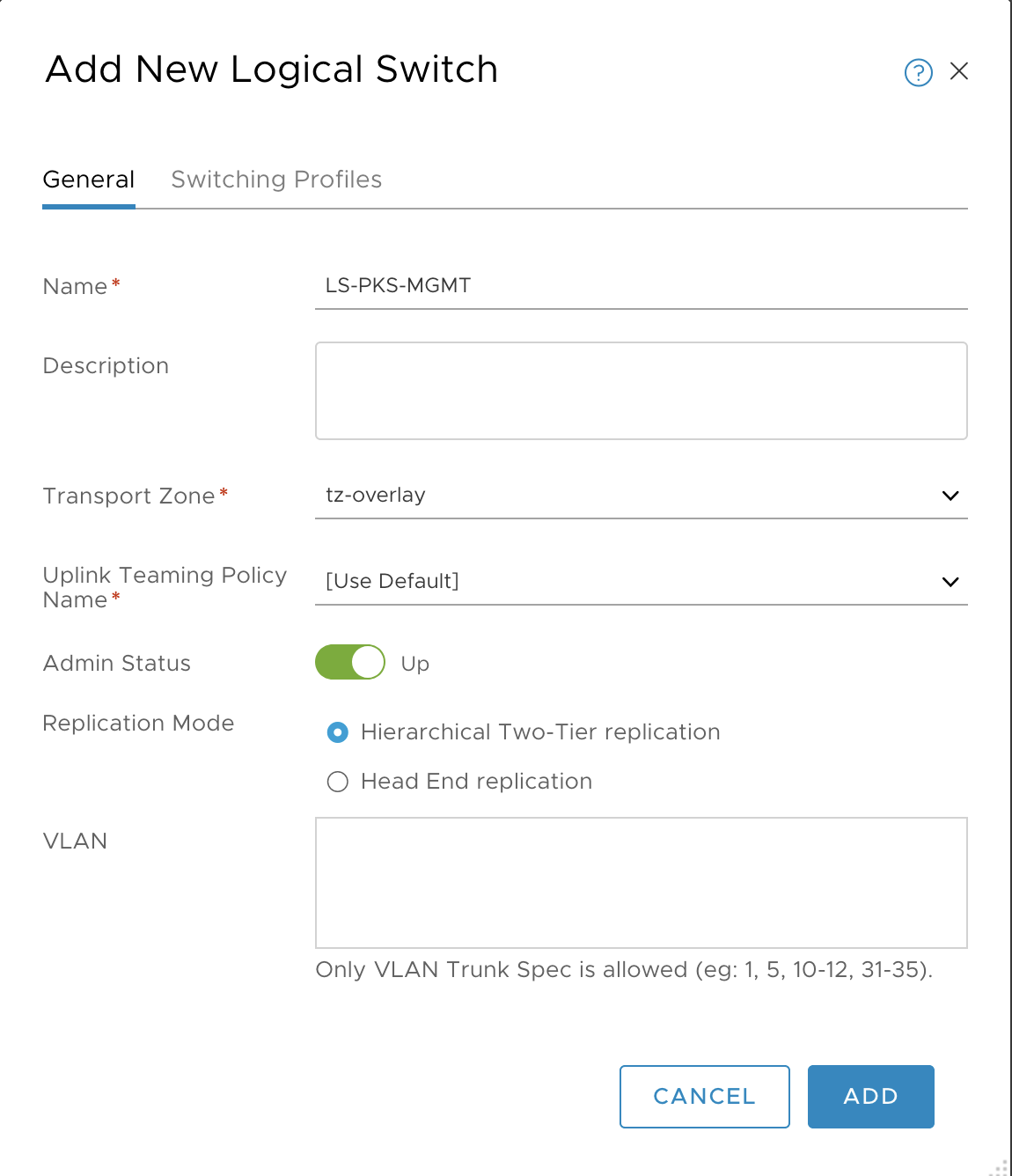
-
Click Add and verify creation of the T1 logical switch.
-
Go to Networking > Tier-1 Logical Router.

-
Click Add.
-
Configure the Tier-1 logical router as follows:
- Name: T1-TKGI-MGMT
- To router: T0-router
- Edge Cluster: edge-cluster-1
- Edge Cluster Members: edge-node-1 and edge-node-2
-
Click Add and verify.
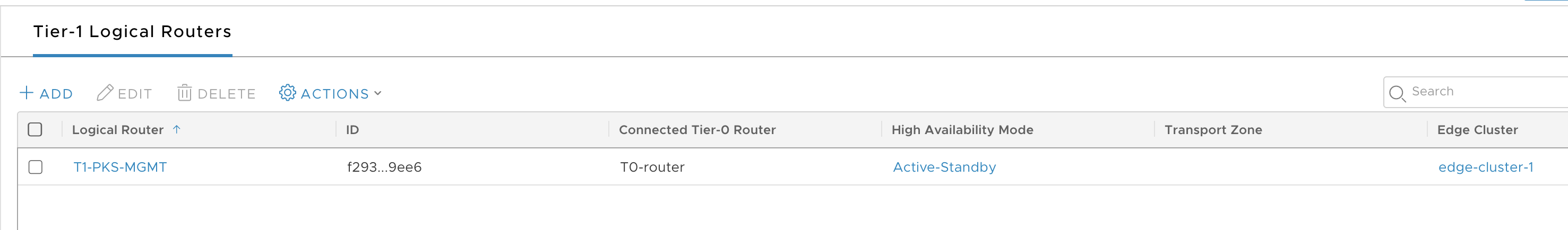
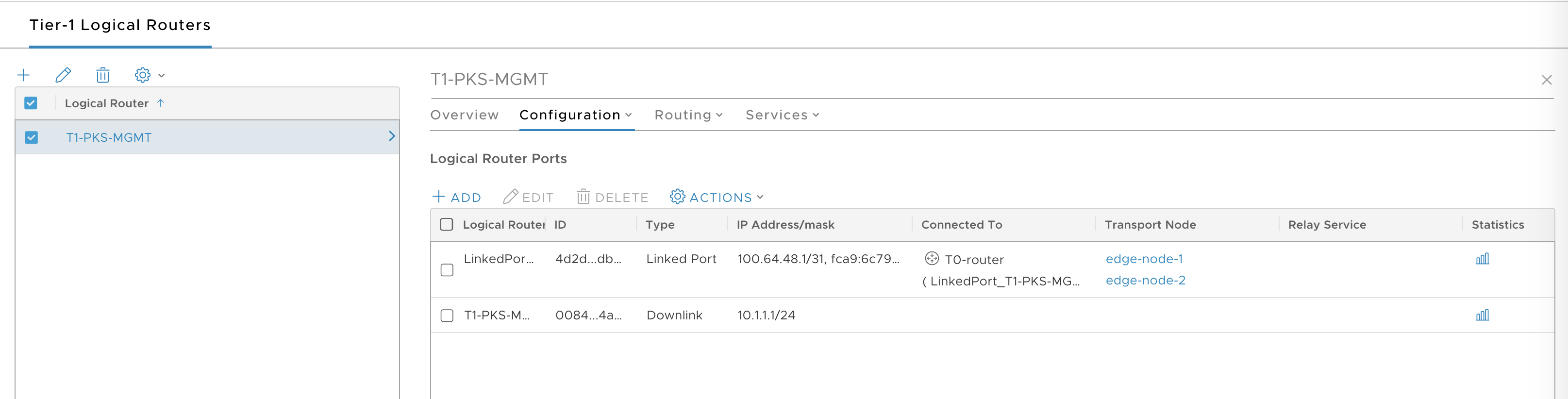
-
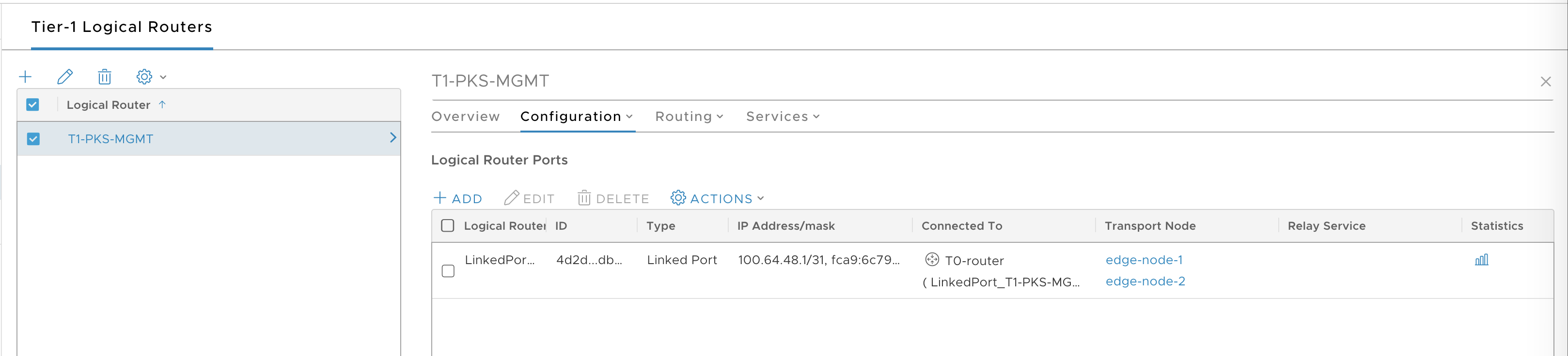
Select the T1 router and go to Configuration > Router port.
-
Click Add.
-
Configure the T1 router port as follows:
- Name: T1-TKGI-MGMT-port
- Logical Switch: LS-TKGI-MGMT
- Subnet: 10.1.1.1/24
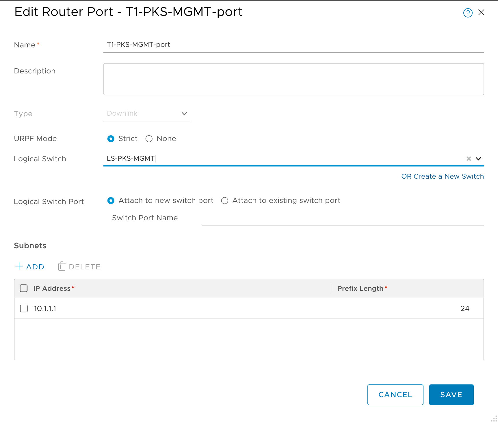
-
Click Add and verify.
-
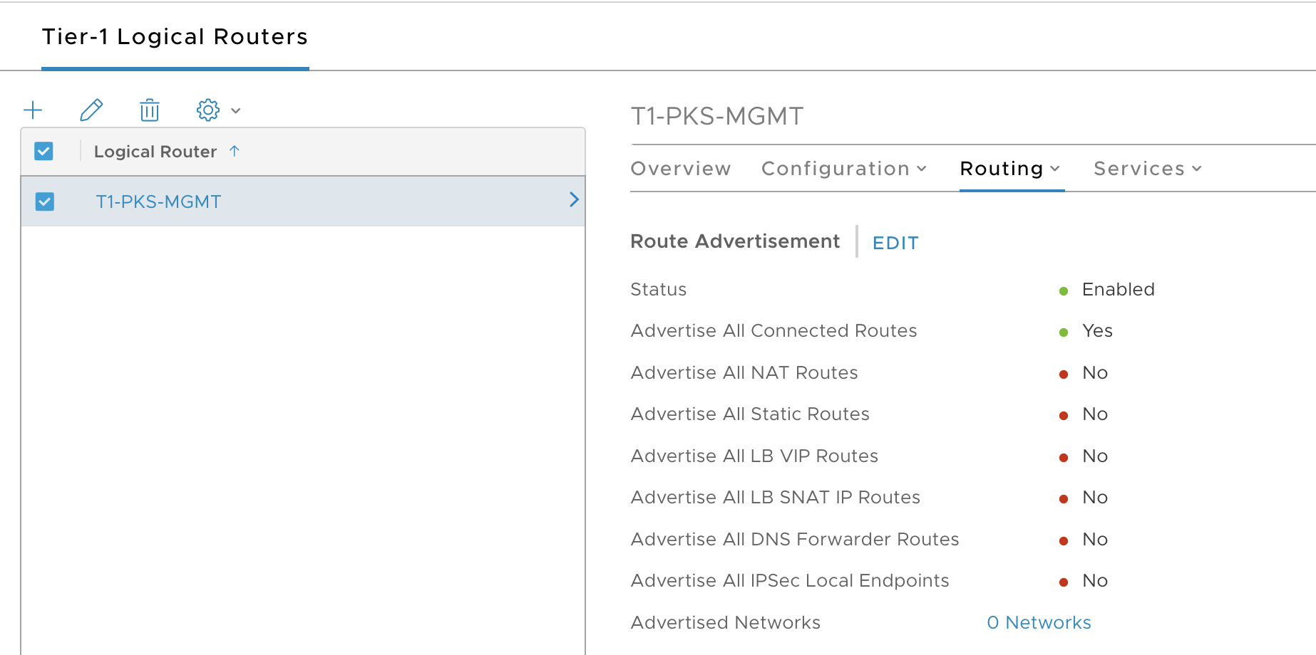
Select Routing tab.
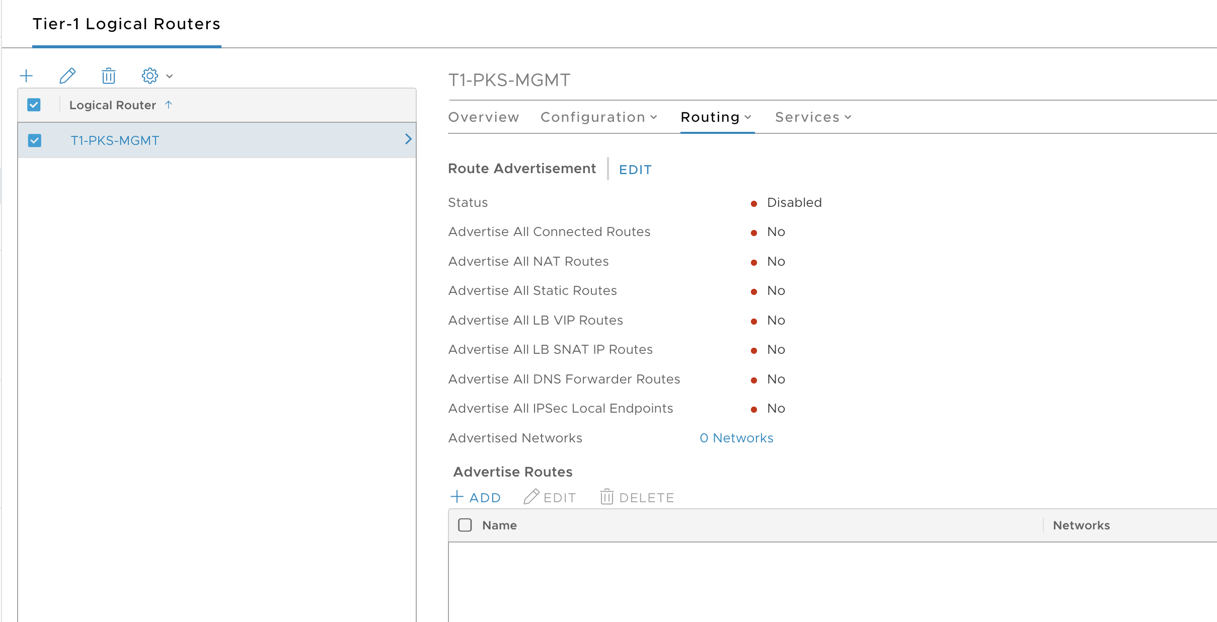
-
Click Edit and configure route advertisement as follows:
- Status: Enabled
- Advertise All Connected Routes: Yes
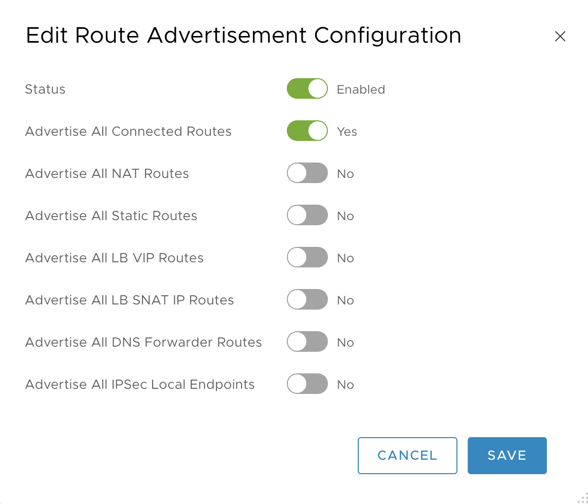
-
Click Save and verify.
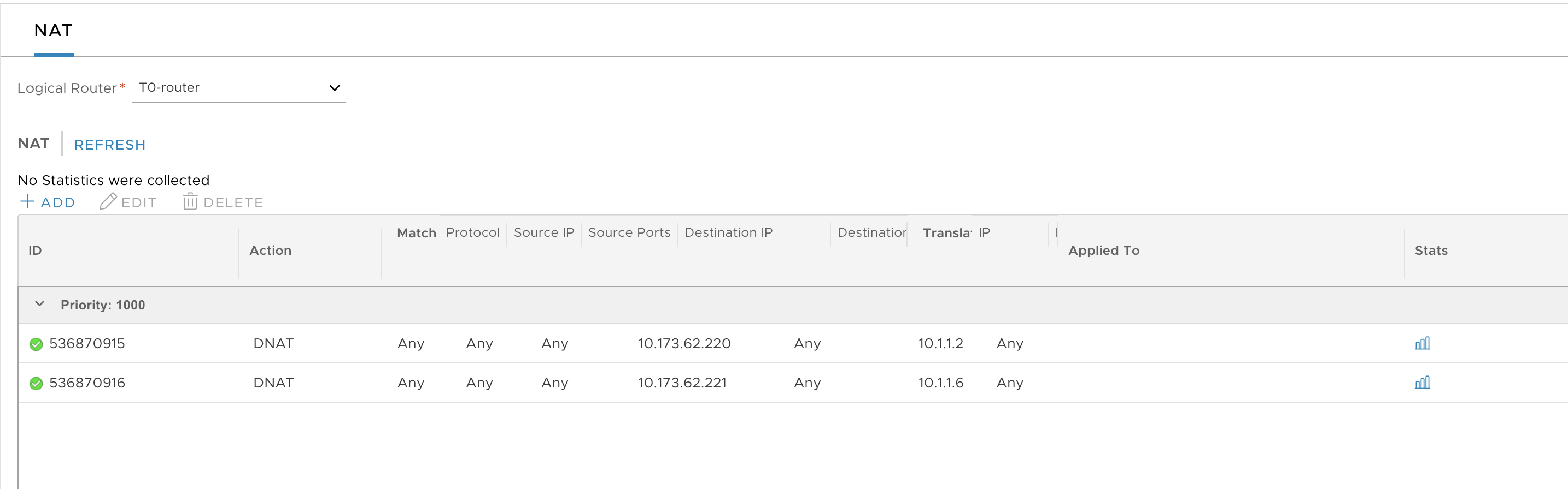
Create NAT Rules
You need to create the following NAT rules on the Tier-0 router for the TKGI Management Plane VMs.
- DNAT:
10.173.62.220(for example) to access Ops Manager - DNAT:
10.173.62.221(for example) to access Harbor -
SNAT:
10.173.62.222(for example) for all TKGI management plane VM traffic destined to the outside world -
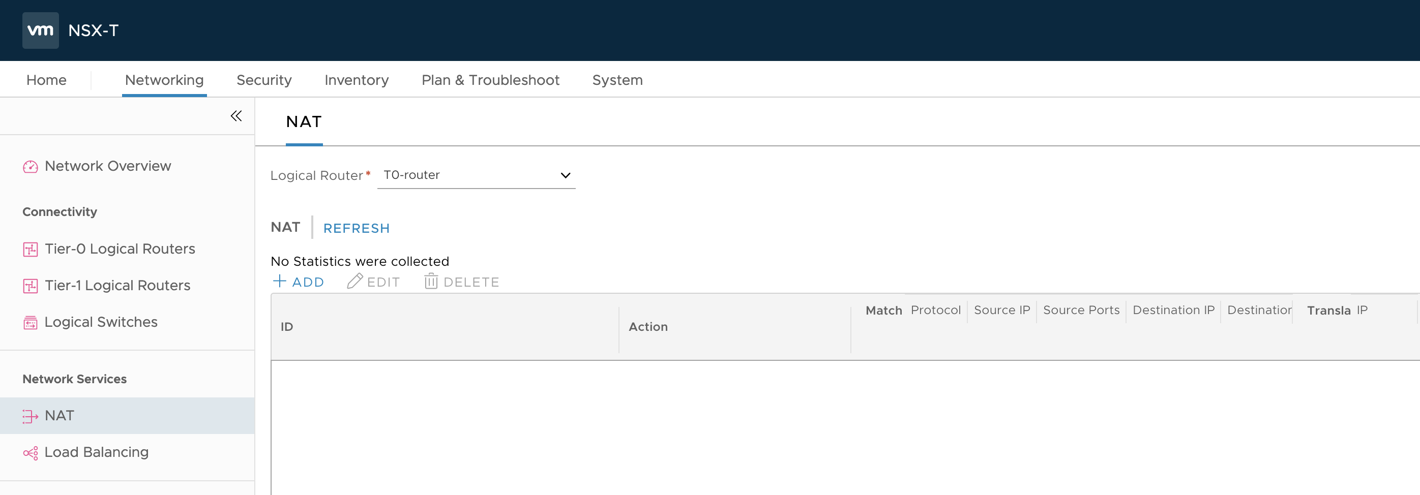
In the NSX Management console, navigate to Networking > NAT.
-
In the Logical Router field, select the T0-router you defined for TKGI.
-
Click Add.
-
Configure the Ops Manager DNAT rule as follows:
- Priority:
1000 - Action:
DNAT - Protocol:
Any Protocol - Destination IP:
10.173.62.220, for example - Translated IP:
10.1.1.2, for example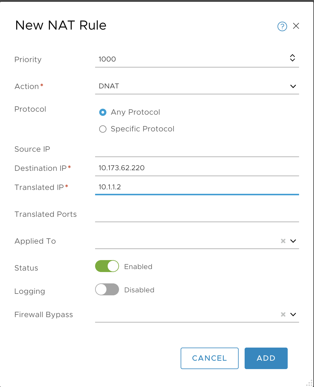
- Priority:
-
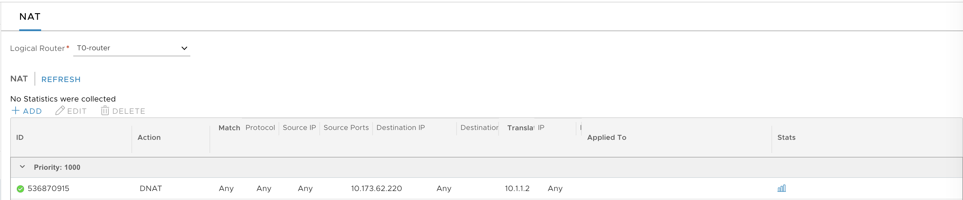
Click Add and verify.
-
Add a second DNAT rule for Harbor by repeating the same operation.
- Priority:
1000 - Action:
DNAT - Protocol:
Any Protocol - Destination IP:
10.173.62.221, for example - Translated IP:
10.1.1.6, for example
- Priority:
-
Verify the creation of the DNAT rules.
-
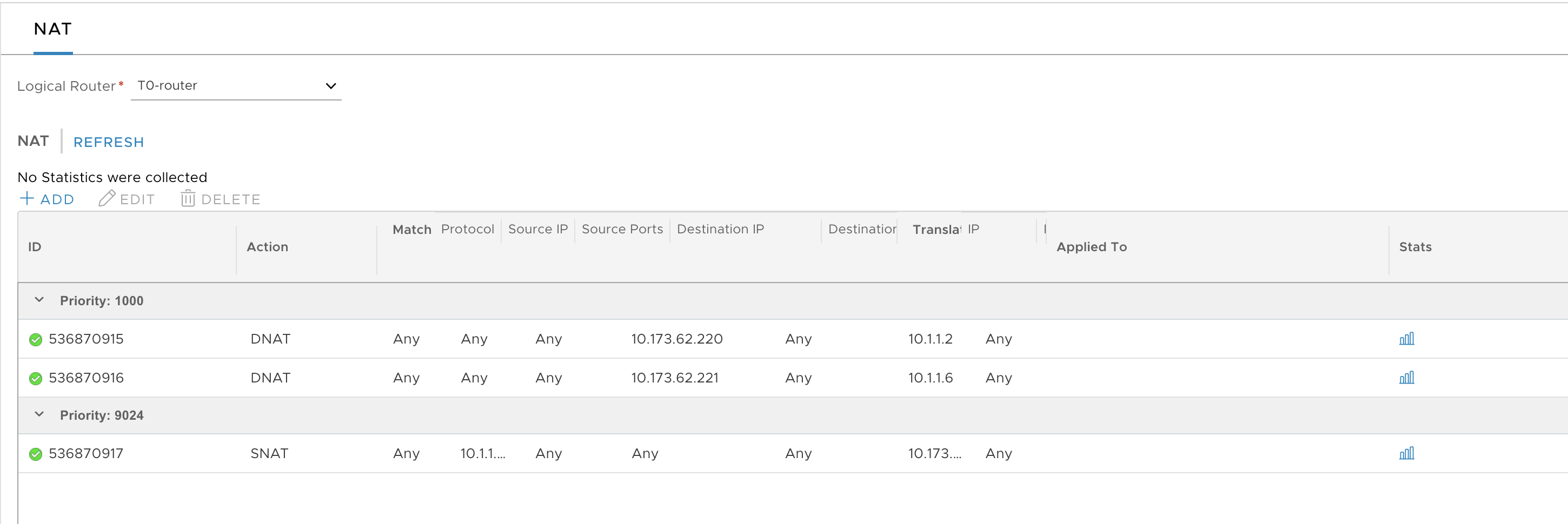
Create the SNAT rule for the management plane traffic as follows:
- Priority:
9024 - Action:
SNAT - Protocol:
Any Protocol - Source IP:
10.1.1.0/24, for example - Translated IP:
10.173.62.222, for example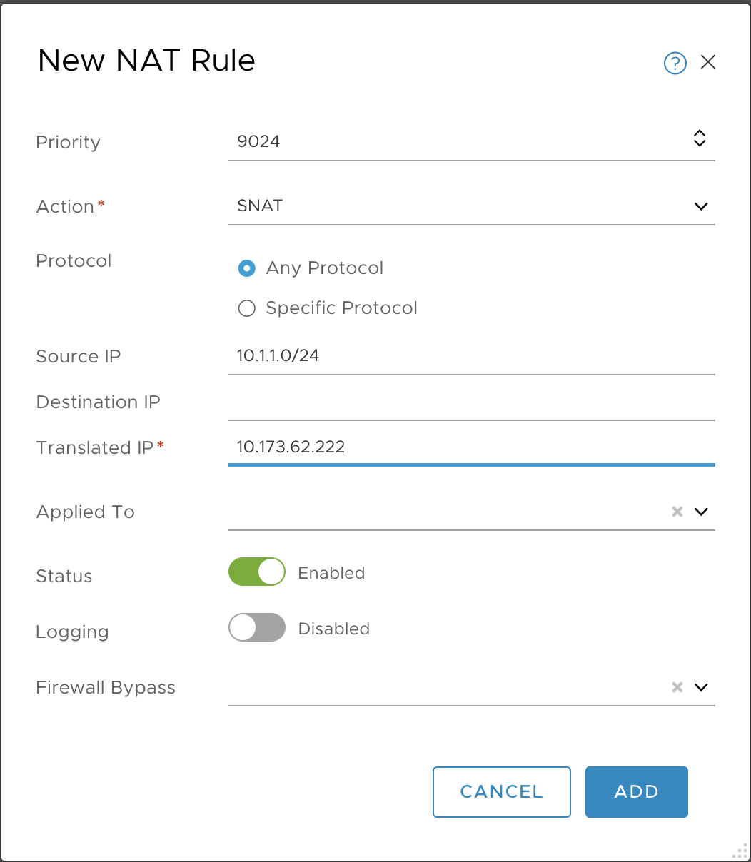
- Priority:
-
Verify the creation of the SNAT rule.
Configure the NSX-T Password Interval (Optional)
The default NSX-T password expiration interval is 90 days. After this period, the NSX-T passwords will expire on all NSX-T Manager Nodes and all NSX-T Edge Nodes. To avoid this, you can extend or remove the password expiration interval, or change the password if needed.
Note: For existing Tanzu Kubernetes Grid Integrated Edition deployments, anytime the NSX-T password is changed you must update the BOSH and TKGI tiles with the new passwords. See Adding Infrastructure Password Changes to the Tanzu Kubernetes Grid Integrated Edition Tile for more information.
Update the NSX-T Manager Password and Password Interval
To update the NSX-T Manager password, perform the following actions on one of the NSX-T Manager nodes. The changes will be propagated to all NSX-T Manager nodes.
SSH into the NSX-T Manager Node
To manage user password expiration, you use the CLI on one of the NSX-T Manager nodes.
To access a NSX-T Manager node, from Unix hosts use the command ssh USERNAME@IP_ADDRESS_OF_NSX_MANAGER.
For example:
ssh [email protected]
On Windows, use PuTTY and provide the IP address for NSX-T Manager. Enter the user name and password that you defined during the installation of NSX-T.
Retrieve the Password Expiration Interval
To retrieve the password expiration interval, use the following command:
get user USERNAME password-expiration
For example:
NSX CLI (Manager, Policy, Controller 3.0.0.0.0.15946739). Press ? for cost or enter: help
nsx-mgr-1> get user admin password-expiration
Password expires 90 days after last change
Update the Admin Password
To update the user password, use the following command:
set user USERNAME password NEW-PASSWORD old-password OLD-PASSWORD.
For example:
set user admin password my-new-pwd old-password my-old-pwd
Set the Admin Password Expiration Interval
To set the password expiration interval, use the following command:
set user USERNAME password-expiration PASSWORD-EXPIRATION.
For example, the following command sets the password expiration interval to 120 days:
set user admin password-expiration 120
Remove the Admin Password Expiration Interval
To remove password expiration, use the following command:
clear user USERNAME password-expiration.
For example:
clear user admin password-expiration
To verify:
nsx-mgr-1> clear user admin password-expiration
nsx-mgr-1> get user admin password-expiration
Password expiration not configured for this user
Update the Password for NSX-T Edge Nodes
To update the NSX-T Edge Node password, perform the following actions on each NSX-T Edge Node.
Note: Unlike the NSX-T Manager nodes, you must update the password or password interval on each Edge Node.
Enable SSH
SSH on the Edge Node is deactivated by default. You have to enable SSH on the Edge Node using the Console from vSphere.
start service ssh
set service ssh start-on-boot
SSH to the NSX-T Edge Node
For example:
ssh [email protected]
Get the Password Expiration Interval for the Edge Node
For example:
nsx-edge> get user admin password-expiration
Password expires 90 days after last change
Update the User Password for the Edge Node
For example:
nsx-edge> set user admin password my-new-pwd old-password my-old-pwd
Set the Password Expiration Interval
For example, the following command sets the password expiration interval to 120 days:
nsx-edge> set user admin password-expiration 120
Remove the Password Expiration Interval
For example:
NSX CLI (Edge 3.0.0.0.0.15946012). Press ? for command list or enter: help
nsx-edge-2> get user admin password-expiration
Password expires 90 days after last change. Current password will expire in 7 days.

nsx-edge-2> clear user admin password-expiration
nsx-edge-2> get user admin password-expiration
Password expiration not configured for this user
Next Steps
Once you have completed the installation of NSX-T v3.0, return to the TKGI installation workflow and proceed with the next phase of the process. See Install Tanzu Kubernetes Grid Integrated Edition on vSphere with NSX-T Using Ops Manager.
