


Deploy Tanzu for Kubernetes Operations on vSphere with VMware VDS
This document provides step-by-step instructions for installing and configuring Tanzu for Kubernetes Operations on a vSphere environment backed by a Virtual Distributed Switch (VDS). The deployment is based on the reference design provided in VMware Tanzu for Kubernetes Operations on vSphere Reference Design. This document does not provide instructions for deploying the underlying SDDC components.
Deploying with VMware Service Installer for Tanzu
You can use VMware Service Installer for VMware Tanzu to automate this deployment.
VMware Service Installer for Tanzu automates the deployment of the reference designs for Tanzu for Kubernetes Operations. It uses best practices for deploying and configuring the required Tanzu for Kubernetes Operations components.
To use Service Installer to automate this deployment, see Deploying VMware Tanzu for Kubernetes Operations on vSphere with vSphere Distributed Switch Using Service Installer for VMware Tanzu.
Alternatively, if you decide to manually deploy each component, follow the steps provided in this document.
Prepare Your Environment for Deploying Tanzu for Kubernetes Operations
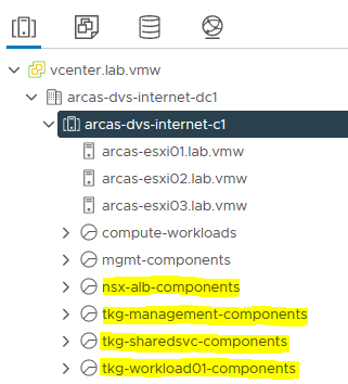
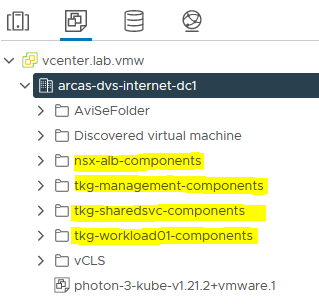
Before you start the deployment, ensure that the required resource pools and folders are created. Following are sample entries of the resource pools and folders.
| Resource Type | Sample Resource Pool Name | Sample Folder Name |
|---|---|---|
| NSX Advanced Load Balancer Components | nsx-alb-components |
nsx-alb-components |
| TKG Management Components | tkg-management-components |
tkg-management-components |
| TKG Shared Service Components | tkg-sharedsvc-components |
tkg-sharedsvc-components |
| TKG Workload components | tkg-workload01-components |
tkg-workload01-components |
The following picture is an example of resource pools in a vSphere environment:
The following picture is an example of VM folders in a vSphere environment:
Overview of the Deployment Steps
The following is an overview of the main steps for deploying Tanzu Kubernetes Operations on vSphere backed by VDS:
Deploy and Configure NSX Advanced Load Balancer
NSX Advanced Load Balancer is an enterprise-grade integrated load balancer that provides L4-L7 Load Balancer support. NSX Advanced Load Balancer is recommended for vSphere deployments without NSX-T, or when there are unique scaling requirements.
For a production-grade deployment, VMware recommends that you deploy 3 instances of the NSX Advanced Load Balancer Controller for high availability and resiliency.
The following is the sample IP address and FQDN set for the NSX Advanced Load Balancer controllers:
| Controller Node | IP Address | FQDN |
|---|---|---|
| Node 1 Primary | 172.16.10.10 | avi01.lab.vmw |
| Node 2 Secondary | 172.16.10.28 | avi02.lab.vmw |
| Node 3 Secondary | 172.16.10.29 | avi03.lab.vmw |
| HA Address | 172.16.10.30 | avi-ha.lab.vmw |
Deploy NSX Advanced Load Balancer
As one of the prerequisites, you must have downloaded the NSX Advanced Load Balancer 20.1.6 Open Virtual Appliance (OVA) and imported it to the content library. Deploy the NSX Advanced Load Balancer under the resource pool “nsx-alb-components” and place it in the “nsx-alb-components” folder.
To deploy NSX Advanced Load Balancer:
-
Log in to vCenter Home Content Libraries.
-
Select the Content Library under which the NSX-ALB OVA is placed.
-
Click OVA & OVF Templates.
-
Right-click NSX ALB Image and select New VM from this Template.
-
On the Select name and folder page, enter a name and select a folder for the NSX Advanced Load Balancer VM as nsx-alb-components.
-
On the Select a compute resource page, select the resource pool as nsx-alb-components.
-
On the Review details page, verify the template details and click Next.
-
On the Select storage page, select a storage policy from the VM Storage Policy drop-down menu and choose the datastore location where you want to store the virtual machine files.
-
On the Select networks page, select the
nsx_alb_management_pgnetwork and click Next. -
On the Customize Template page, provide the NSX Advanced Load Balancer Management network details, such as IP Address, Subnet Mask, and Gateway, and click Next. Note: If you choose to use DHCP, you can leave these entries blank.
-
On the Ready to complete page, review the page and click Finish.
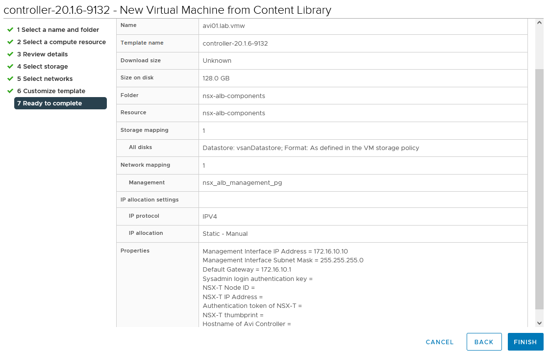
A new task for creating the virtual machine appears in the Recent Tasks pane. After the task is complete, the NSX Advanced Load Balancer virtual machine is created on the selected resource. Power on the virtual machine and give it few minutes for the system to boot.
Note: While the system is booting up, a blank web page or a 503 status code may appear.
NSX Advanced Load Balancer: Initial setup
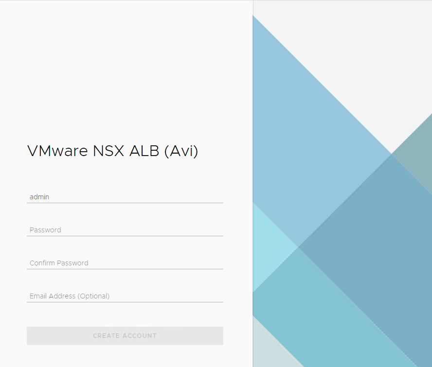
Once the NSX Advanced Load Balancer is successfully deployed and boots up, navigate to NSX Advanced Load Balancer on your browser using the URL “https://<AVI_IP/FQDN>” and configure the basic system settings:
-
Administrator account setup. Set an admin password and click Create Account.
-
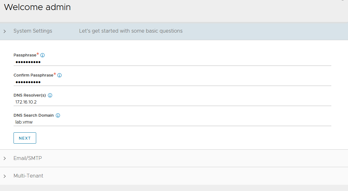
On the Welcome admin page:
-
Under System Settings: Set backup Passphrase and provide DNS information and click Next.
-
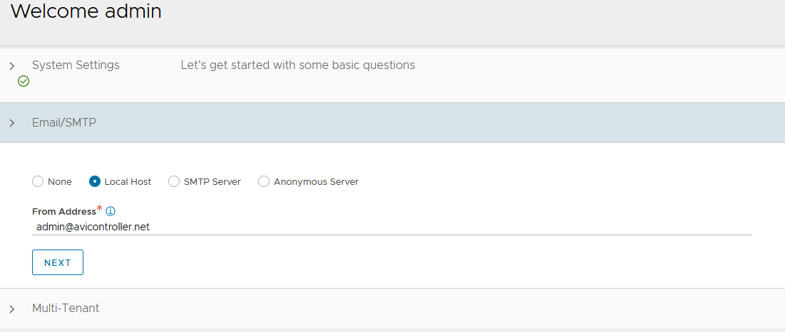
Under Email/SMTP: Provide Email or SMTP information.
-
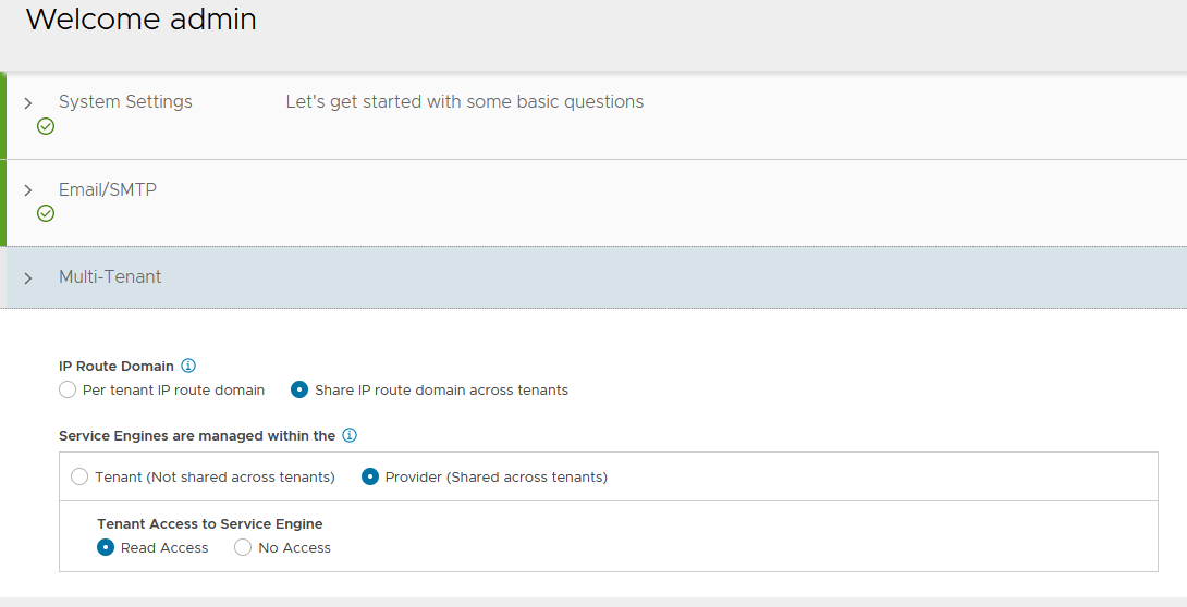
Under Multi-Tenant: Configure settings as shown and click Save IP Route Domain: Share IP route domain across tenants Service Engines are managed within the: Provider (Shared across tenants) Tenant Access to Service Engine: Read Access
-
-
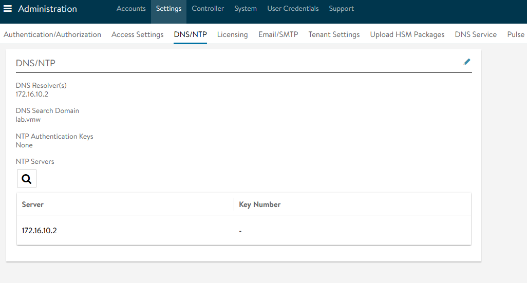
Go to Administration Settings DNS/NTP Edit to add your NTP server details and Save.
Note: You may also delete the default NTP servers.
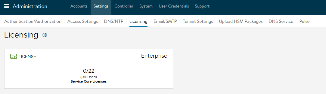
NSX Advanced Load Balancer: Licensing
By default, the evaluation license uses Enterprise licensing. If you plan to use the Enterprise Licensing for your deployment, you may add your license key in the licensing section. If not, change the license model to Essentials.
See NSX Advanced Load Balancer Editions for a comparison of available licensing editions.
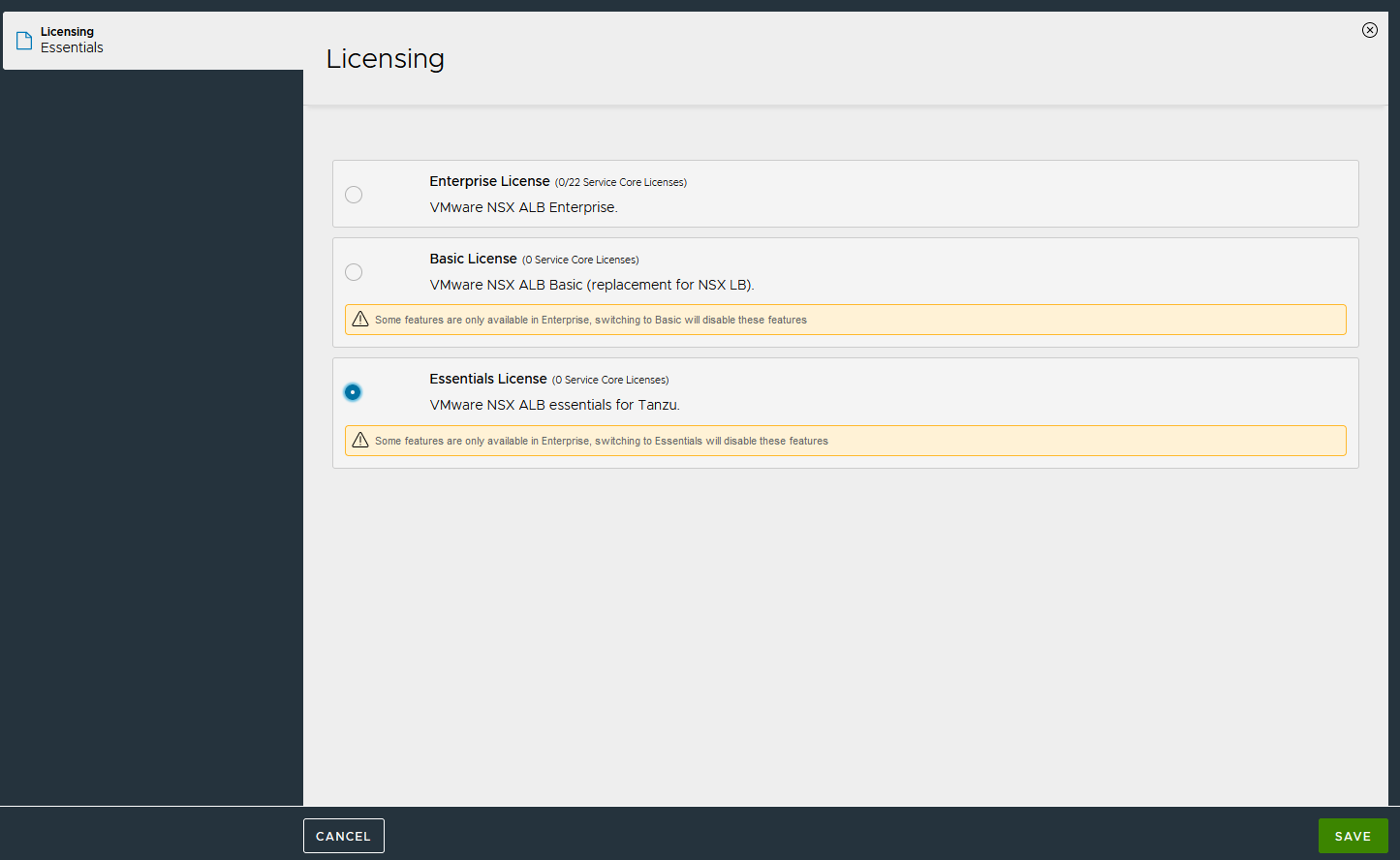
To change the license edition to Essentials:
-
Log in to NSX Advanced Load Balancer Administration Settings Licensing. On the Licensing page, click gear icon next to Licensing**. **
-
Select Essentials License and click Save.
NSX Advanced Load Balancer: Controller High Availability
NSX Advanced Load Balancer can run with a single controller (single-node deployment) or with a 3-node controller cluster. In a deployment that uses a single controller, that controller performs all administrative functions as well as all analytics data gathering and processing.
Adding 2 additional nodes to create a 3-node cluster provides node-level redundancy for the controller and also maximizes performance for CPU-intensive analytics functions.
In a 3-node NSX Advanced Load Balancer Controller cluster, one node is the primary (leader) node and performs the administrative functions. The other two nodes are followers (secondaries) and perform data collection for analytics, in addition to standing by as backups for the leader. Perform the following steps to configure AVI Advanced Load Balancer HA:
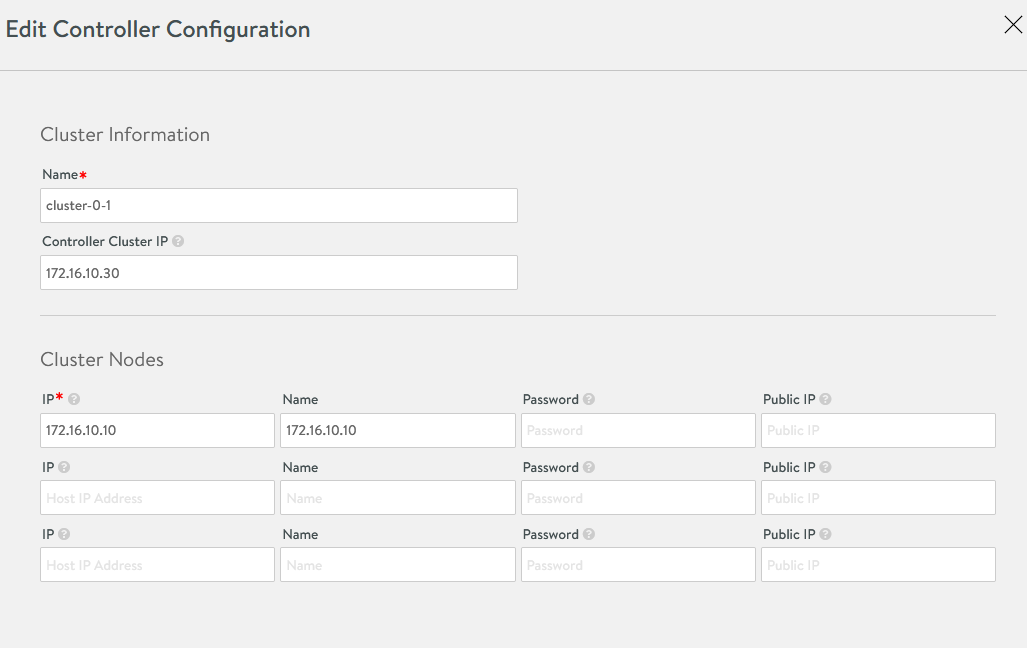
-
Set the Cluster IP for the NSX Advanced Load Balancer controller Log in to the primary NSX Advanced Load Balancer controller. Navigate to Administrator Controller Nodes, and click Edit. The Edit Controller Configuration popup appears
-
In the Controller Cluster IP field, enter the Controller Cluster IP for the controller and click Save.
-
Deploy the 2nd and 3rd NSX Advanced Load Balancer nodes, following the steps provided in Deploy NSX Advanced Load Balancer.
-
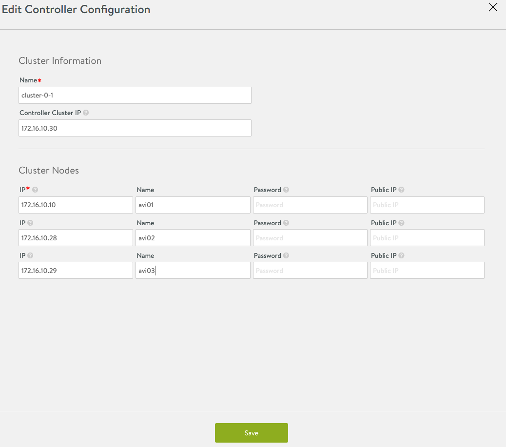
Log in to the Primary NSX Advanced Load Balancer controller using the Controller Cluster IP/FQDN, navigate to Administrator Controller Nodes, and click Edit. The Edit Controller Configuration popup appears.
-
In the Cluster Nodes field, enter the IP address for the 2nd and 3rd controllers and click Save.
Optional: Provide a friendly name for all 3 nodes.
After these steps, the primary Avi Controller becomes the leader for the cluster and invites the other controllers to the cluster as members.
NSX Advanced Load Balancer then performs a warm reboot of the cluster. This process can take 2-3 minutes. The configuration of the primary (leader) controller is synchronized to the new member nodes when the cluster comes online following the reboot.
Once the cluster is successfully formed, you should see the following status: 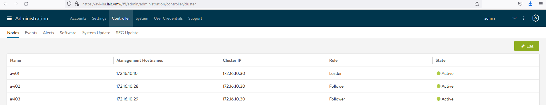
Note: After the cluster is formed, all NSX Advanced Load Balancer configurations are done by connecting to the NSX Advanced Load Balancer Controller Cluster IP/FQDN.
NSX Advanced Load Balancer: Certificate Management
The default system-generated controller certificate generated for SSL/TSL connections will not have required SAN entries. Follow the following steps to create a Controller certificate:
-
Log in to NSX Advanced Load Balancer Controller Templates Security SSL/TLS Certificates
-
Click Create and select Controller Certificate
-
You can either generate a Self-Signed certificate, generate a Certificate Signing Request (CSR), or import a certificate. For the purpose of this document, a self-signed certificate will be generated.
-
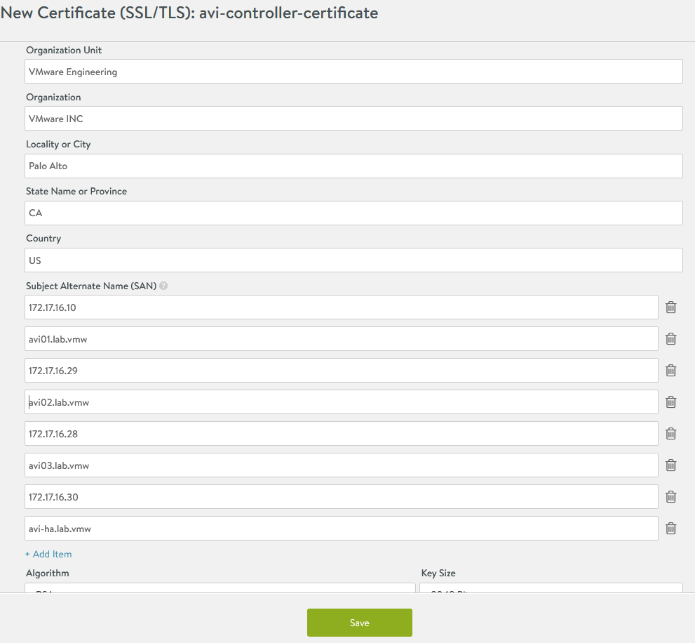
Provide all required details as per your infrastructure requirements. Under the Subject Alternate Name (SAN) section, provide the IP address and Fully Qualified Domain Name (FQDN) of all NSX Advanced Load Balancer controllers, including the IP address and FQDN of the NSX Advanced Load Balancer cluster, and click Save.
-
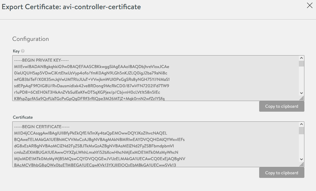
Once the certificate is created, capture the certificate contents. You will need this when you deploy the Tanzu Kubernetes Grid management cluster.
To capture the certificate content, click the “Download” icon next to the certificate, and then click “Copy to clipboard” under the Certificate section.
-
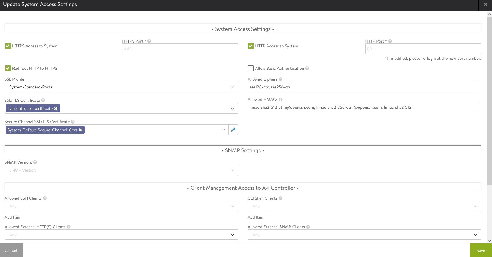
To replace the certificate, navigate to Administration Settings Access Settings, and click the pencil icon at the top right to edit the System Access Settings, replace the SSL/TSL certificate, and click Save.
-
To complete the certificate configuration, log out and log back in to the NSX Advanced Load Balancer.
NSX Advanced Load Balancer: Create vCenter Cloud and SE Groups
Avi Vantage may be deployed in multiple environments for the same system. Each environment is called a cloud. The following procedure provides steps on how to create a VMware vCenter cloud. As shown in the architecture, two Service Engine (SE) Groups will be created: Service Engine Group 1: Service engines in this group host:
-
Virtual services for all load balancer functionalities requested by the Tanzu Kubernetes Grid management and workload clusters
-
Virtual services that load balance the control plane nodes of all Tanzu Kubernetes Grid Kubernetes clusters
Service Engine Group 2: Service engines part of this Service Engine group hosts virtual services for all load balancer functionalities requested by Tanzu Kubernetes Grid Workload clusters mapped to this SE group.
-
Based on your requirements, you can create additional Service Engine groups for the workload clusters.
-
Multiple Workload clusters can be mapped to a single SE group.
-
A Tanzu Kubernetes Grid cluster can be mapped to only one SE group for Advanced Load Balancer services. See Configure NSX Advanced Load Balancer in Tanzu Kubernetes Grid Workload Cluster for more details on mapping a specific SE group to a Tanzu Kubernetes Grid workload cluster.
The following components will be created in NSX Advanced Load Balancer:
| Object | Sample Name |
|---|---|
| vCenter Cloud | tanzu-vcenter01 |
| Service Engine Group 1 | tanzu-mgmt-segroup-01 |
| Service Engine Group 2 | tanzu-wkld-segroup-01 |
-
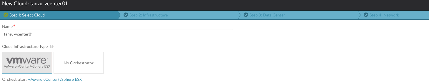
Log in to NSX ALB > Infrastructure > Clouds > Create > VMware vCenter/vSphere ESX
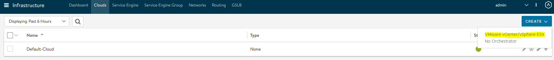
-
Provide the cloud name and click Next.
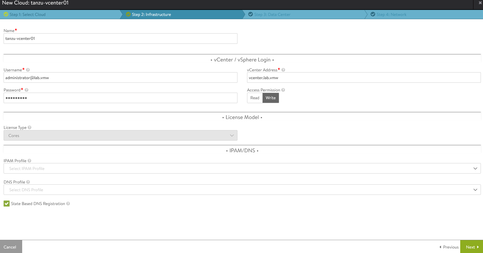
-
Under the Infrastructure pane, provide vCenter Address, username, and password. Set Access Permission to “Write” and click Next.
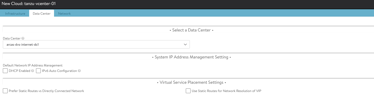
-
Under the Datacenter pane, choose the datacenter for NSX Advanced Load Balancer to discover infrastructure resources.
-
Under the Network pane, choose the NSX Advanced Load Balancer Management Network for Service Engines and provide a Static IP pool for SEs and VIP and click Complete.
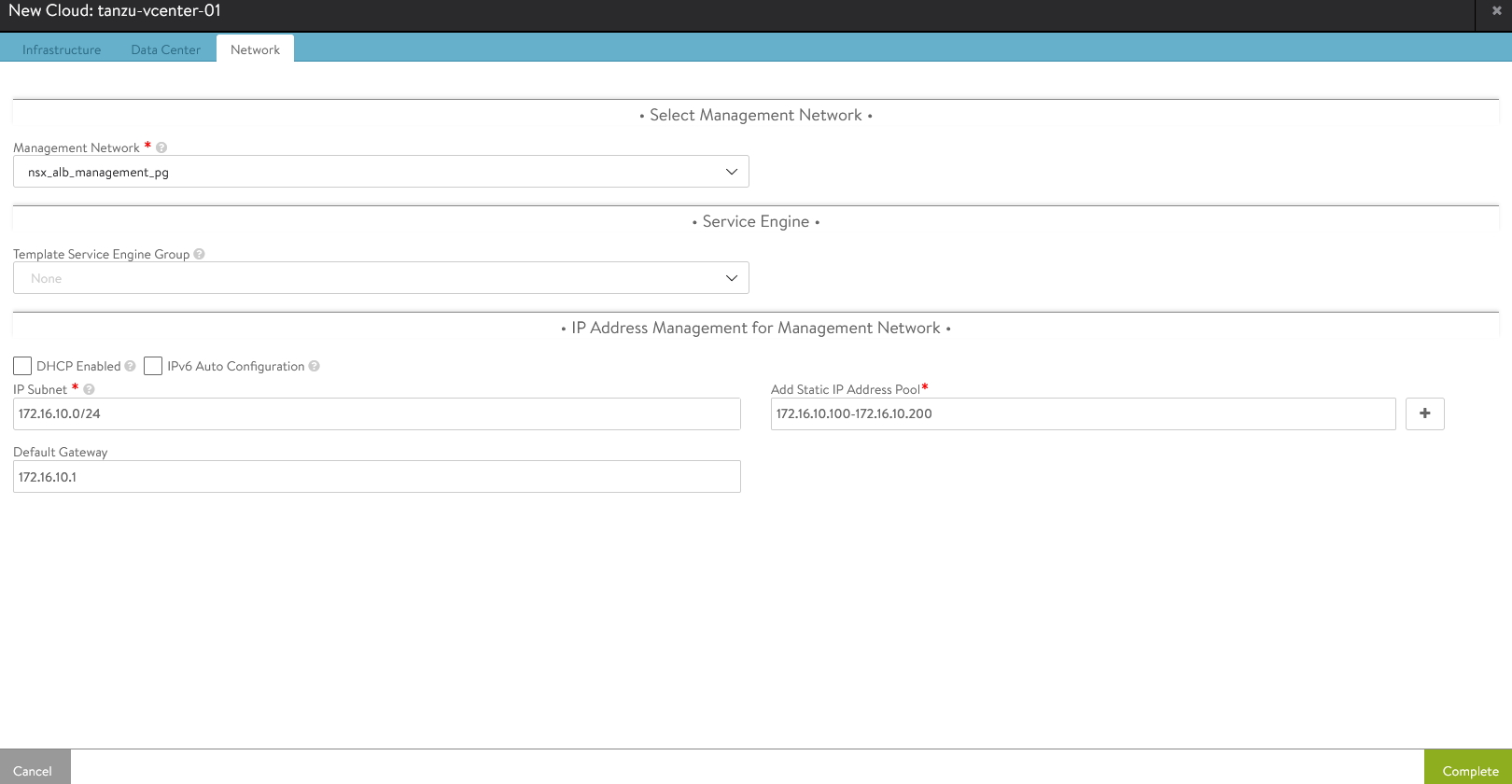
-
Wait for the cloud to configure and the cloud status indicator to turn green.
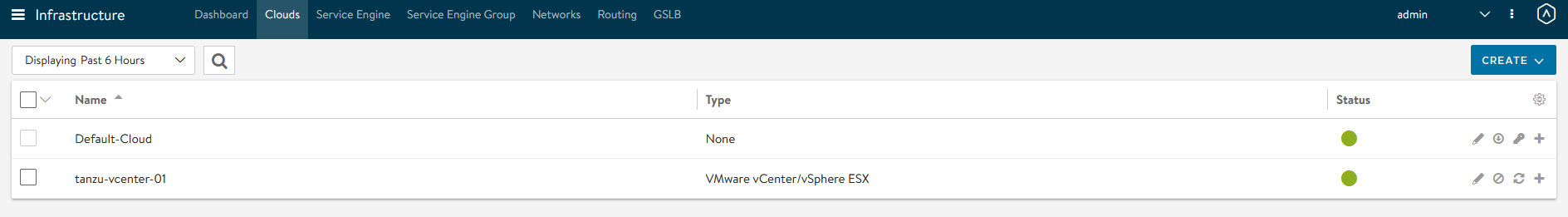
-
To create a Service Engine group for Tanzu Kubernetes Grid management clusters, click the Service Engine Group tab. Under Select Cloud, choose the cloud created in the previous step, and click Create.
-
Provide a name for the Tanzu Kubernetes Grid management Service Engine group and set the following parameters:
Parameter Value High availability mode Active/Standby (Tanzu Essentials License supports only Active/Standby Mode Memory per Service Engine 4 vCPU per Service Engine 2 Leave the remaining parameters at their default settings.
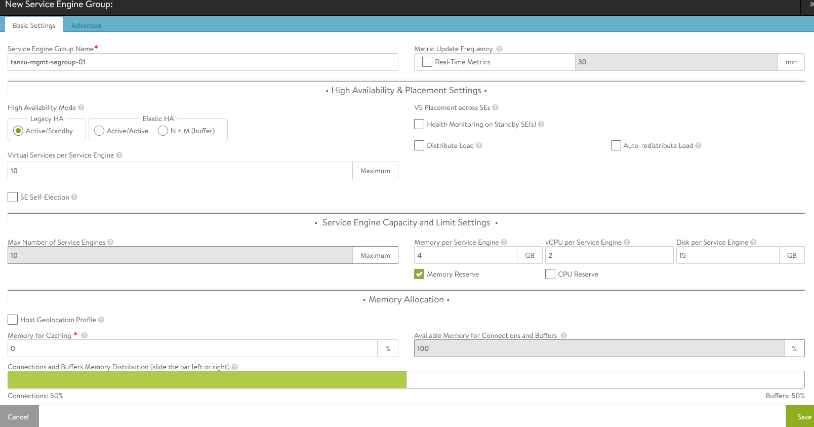
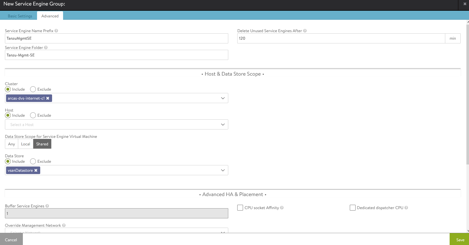
-
For advanced configuration, click the Advanced tab. Here you can set the AVI service engine folder and service engine name prefix and select a specific cluster and datastore for service engine placement. Click Save when you are done.
-
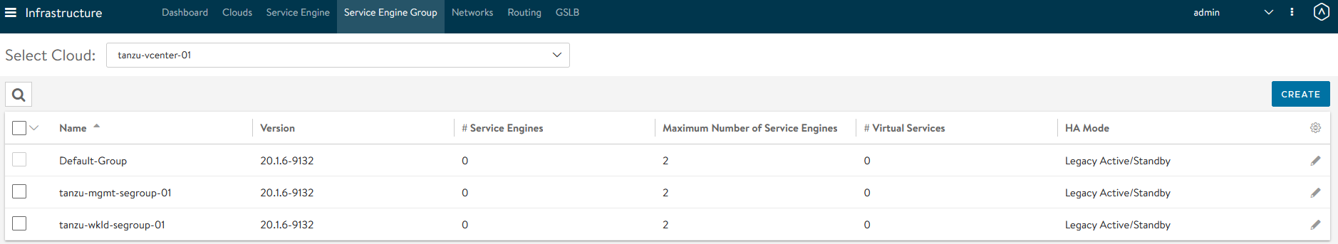
Follow steps 7 and 8 to create another SE group for Tanzu Kubernetes Grid workload clusters. Once complete, there will be two SE groups created.
NSX Advanced Load Balancer: Configure Network and IPAM Profile
Configure Tanzu Kubernetes Grid Networks in NSX Advanced Load Balancer
As part of the cloud creation in NSX Advanced Load Balancer, only the Management Network has been configured in NSX Advanced Load Balancer. Follow this procedure to configure these networks:
- TKG Management Network
- TKG Workload Network
- TKG Cluster VIP/Data Network
- TKG Management VIP/Data Network
-
TKG Workload VIP/Data Network
-
Log in to NSX Advanced Load Balancer Infrastructure Networks
-
Select the appropriate Cloud
All the networks available in vCenter will be listed.
-
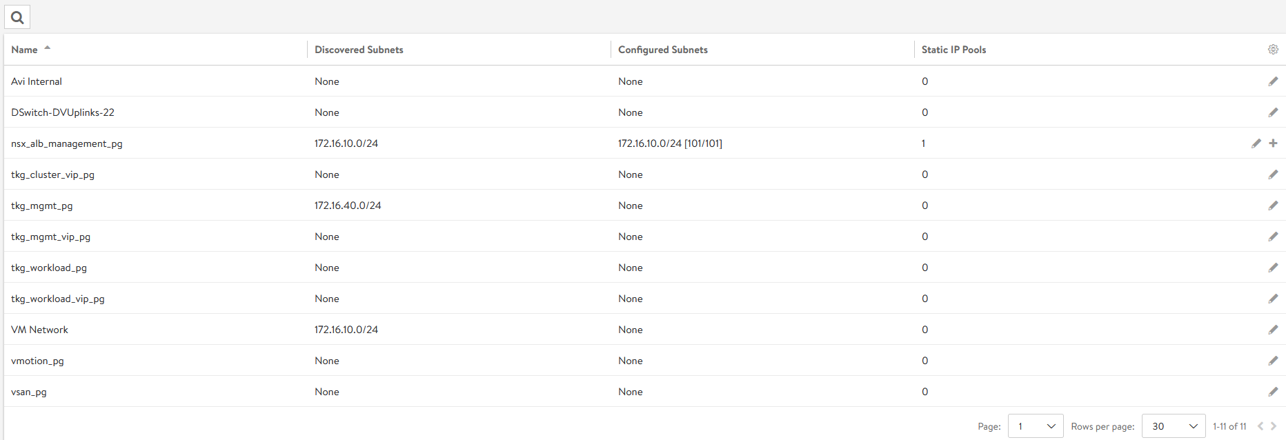
Click the edit icon for the network and configure as shown. Change the details provided in the table according to your SDDC configuration. Note: Not all networks will be auto-discovered. For those that are not, add the subnet manually.
Network Name DHCP Subnet Static IP Pool tkg_mgmt_pgYes 172.16.40.0/24 NA tkg_workload_pgYes 172.16.60.0/24 NA tkg_cluster_vip_pgNo 172.16.80.0/24 172.16.80.100 - 172.16.80.200 tkg_mgmt_vip_pgNo 172.16.50.0/24 172.16.50.100 - 172.16.50.200 tkg_workload_vip_pgNo 172.16.70.0/24 172.16.70.100 - 172.16.70.200 The following snippet shows the configuration of one of the networks, for example:
tkg_cluster_vip_pg:
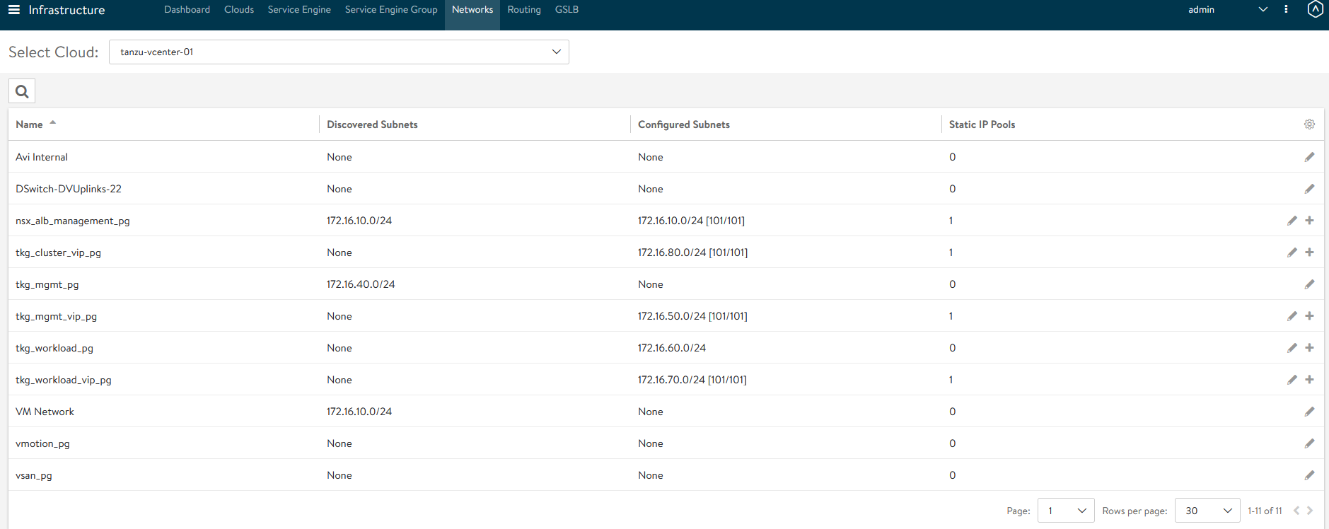
Once the networks are configured, the configuration must look as shown:
-
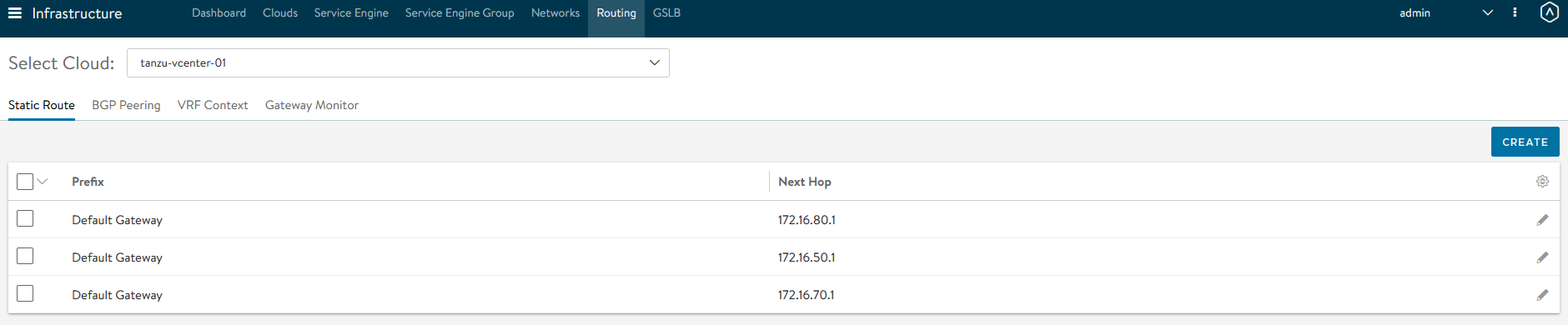
After the networks are configured, set the default routes for all VIP/Data networks. Click Routing. Create and add default routes for following networks. Change the gateway subnet to match your network configuration:
Network Name Gateway Subnet Next Hop tkg_cluster_vip_pg 0.0.0.0/0 172.16.80.1 tkg_mgmt_vip_pg 0.0.0.0/0 172.16.50.1 tkg_workload_vip_pg 0.0.0.0/0 172.16.70.1
Create IPAM Profile in NSX Advanced Load Balancer and Attach it to Cloud
At this point, all the networks required for Tanzu functionality are configured in NSX Advanced Load Balancer, except for the TKG Management and Workload Networks, which use DHCP. NSX Advanced Load Balancer provides IPAM service for the TKG Cluster VIP network, the TKG Management VIP network, and the TKG Workload VIP network. The following procedure creates an IPAM profile and attaches it to the vCenter cloud created earlier.
-
Log in to NSX Advanced Load Balancer Infrastructure Templates IPAM/DNS Profiles Create IPAM Profile and provide the following details and click Save.
Parameter Value Name tanzu-vcenter-ipam-01 Type AVI Vintage IPAM Cloud for Usable Networks Tanzu-vcenter-01, created here Usable Networks tkg_cluster_vip_pg
tkg_mgmt_vip_pg
tkg_workload_vip_pg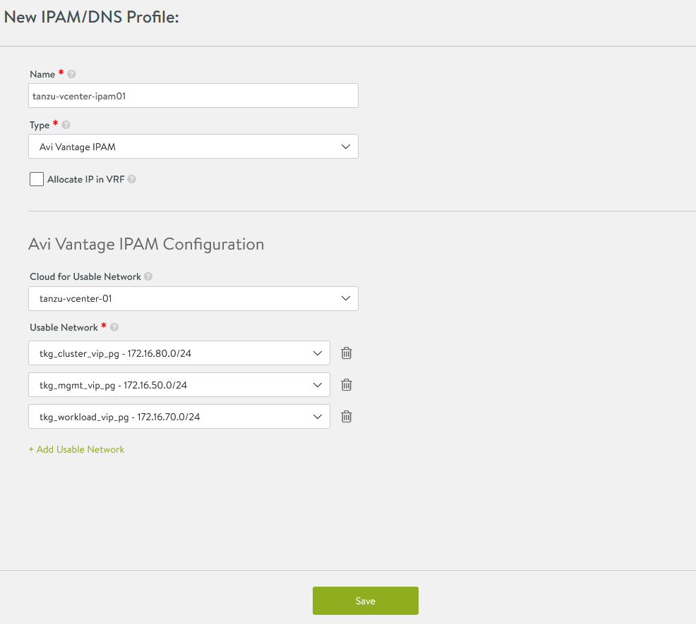
-
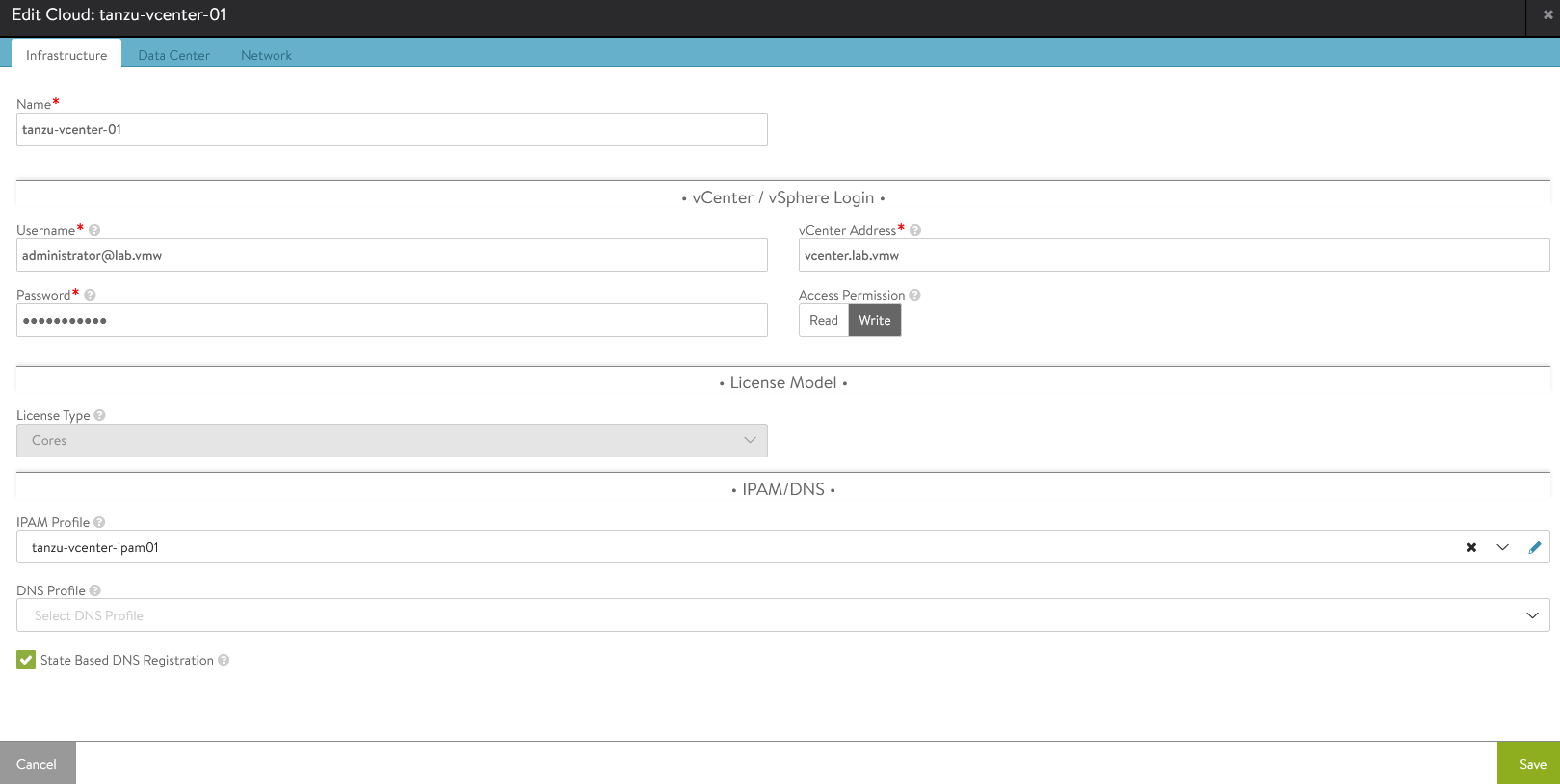
Attach the IPAM profile to the “tanzu-vcenter-01” cloud:
- Navigate to Infrastructure Clouds.
- Edit the tanzu-vcenter-01 cloud.
- Under IPAM Profile, choose the profile created in the previous step and Save the configuration,
This completes the NSX Advanced Load Balancer configuration. Next is to deploy and configure the bootstrap machine that will be used to deploy and manage Tanzu Kubernetes clusters.
Deploy and Configure Bootstrap Machine
The bootstrap machine can be a laptop, host, or server (running on a Linux/MAC/Windows platform) that you deploy management and workload clusters from, and that keeps the Tanzu and Kubernetes configuration files for your deployments. The bootstrap machine is typically local.
For the purpose of this document, the bootstrap server is a Photon-based virtual machine. See Install the Tanzu CLI and Other Tools to configure MAC/Windows machines.
-
Ensure that the bootstrap VM is connected to TKG Management Network
tkg_mgmt_pg. -
Configure NTP on your bootstrap machine.
-
For this example using the Photon OS, download and unpack following Linux CLI packages from myvmware
-
VMware Tanzu CLI for Linux
-
kubectl cluster cli v1.21.2 for Linux
-
-
Execute the following commands to install the Tanzu Kubernetes Grid CLI, Kubectl CLIs, and Carvel tools:
## Install required packages tdnf install tar zip unzip wget -y ## Install TKG CLI tar -xvf tanzu-cli-bundle-linux-amd64.tar cd ./cli/ sudo install core/v1.5.0/tanzu-core-linux_amd64 /usr/local/bin/tanzu chmod +x /usr/local/bin/tanzu ## Install TKG CLI Plugins tanzu plugin install --local ./cli all ## Install Kubectl CLI gunzip kubectl-linux-v1.21.2+vmware.1.gz mv kubectl-linux-v1.21.2+vmware.1 /usr/local/bin/kubectl && chmod +x /usr/local/bin/kubectl # Instal Carvel tools cd ./cli gunzip ytt-linux-amd64-v0.34.0+vmware.1.gz chmod ugo+x ytt-linux-amd64-v0.34.0+vmware.1 && mv ./ytt-linux-amd64-v0.34.0+vmware.1 /usr/local/bin/ytt cd ./cli gunzip kapp-linux-amd64-v0.37.0+vmware.1.gz chmod ugo+x kapp-linux-amd64-v0.37.0+vmware.1 && mv ./kapp-linux-amd64-v0.37.0+vmware.1 /usr/local/bin/kapp cd ./cli gunzip kbld-linux-amd64-v0.30.0+vmware.1.gz chmod ugo+x kbld-linux-amd64-v0.30.0+vmware.1 && mv ./kbld-linux-amd64-v0.30.0+vmware.1 /usr/local/bin/kbld cd ./cli gunzip imgpkg-linux-amd64-v0.10.0+vmware.1.gz chmod ugo+x imgpkg-linux-amd64-v0.10.0+vmware.1 && mv ./imgpkg-linux-amd64-v0.10.0+vmware.1 /usr/local/bin/imgpkg -
Validate the Carvel tools installation using the following commands:
ytt version kapp version kbld version imgpkg version -
Install
yq.yqis a lightweight and portable command-line YAML processor.yqusesjq-like syntax but works with yaml files as well as json.wget https://github.com/mikefarah/yq/releases/download/v4.13.4/yq_linux_amd64.tar.gz tar -xvf yq_linux_amd64.tar && mv yq_linux_amd64 /usr/local/bin/yq -
By default, Photon OS has Docker installed. Use the following commands to start the Docker service and enable it to start at boot.
## Check Docker service status systemctl status docker ## Start Docker Service systemctl start docker ## To start Docker Service at boot systemctl enable docker -
Ensure that the bootstrap machine is using cgroup v1 by running the following command:
docker info | grep -i cgroup ## You should see the following: Cgroup Driver: cgroupfs -
Create an SSH Key Pair. This is required for Tanzu CLI to connect to vSphere from the bootstrap machine. The public key part of the generated key will be passed during the Tanzu Kubernetes Grid management cluster deployment.
## Generate SSH key pair ## When prompted enter file in which to save the key (/root/.ssh/id_rsa): press Enter to accept the default and provide password ssh-keygen -t rsa -b 4096 -C "[email protected]" ## Add the private key to the SSH agent running on your machine, and enter the password you created in the previous step. ssh-add ~/.ssh/id_rsa ## If this command fails, execute "eval $(ssh-agent)" and then rerun the command. -
If your bootstrap machine runs Linux or Windows Subsystem for Linux, and it has a Linux kernel built after the May 2021 Linux security patch, for example Linux 5.11 and 5.12 with Fedora, run the following:
sudo sysctl net/netfilter/nf_conntrack_max=131072
Now all the required packages are installed and the required configurations are in place in the bootstrap virtual machines. Proceed to the next section to deploy the Tanzu Kubernetes Grid management cluster.
Deploy Tanzu Kubernetes Grid Management Cluster
After you have performed the steps described in deploy and configure bootstrap machine, you can deploy the Tanzu Kubernetes Grid management cluster.
The management cluster is a Kubernetes cluster that runs cluster API operations on a specific cloud provider to create and manage workload clusters on that provider.
The management cluster is also where you configure the shared and in-cluster services utilized by the workload clusters. You may deploy management clusters in two ways:
-
Run the Tanzu Kubernetes Grid installer, a wizard interface that guides you through the process of deploying a management cluster. This is the recommended method.
-
Create and edit YAML configuration files, and use them with CLI commands to deploy a management cluster.
You may deploy and manage Tanzu Kubernetes Grid management clusters on:
-
vSphere 6.7u3
-
vSphere 7, if vSphere with Tanzu is not enabled.
Import Base Image template for Tanzu Kubernetes Grid Cluster Deployment
Before create the management cluster, ensure that the base image template is imported into vSphere and is available as a template. To import a base image template into vSphere:
-
Go to the Tanzu Kubernetes Grid downloads page, and download a Tanzu Kubernetes Grid OVA for the cluster nodes.
-
For the management cluster, this must be either a Photon- or Ubuntu-based Kubernetes v1.21.2 OVA.
Note: Custom OVA with a custom Tanzu Kubernetes release (TKr) is also supported, as described in Build Machine Images.
-
For workload clusters, OVA can have any supported combination of OS and Kubernetes versions, as packaged in a Tanzu Kubernetes release
Important: Make sure you download the most recent OVA base image templates in the event of security patch releases. You can find updated base image templates that include security patches on the Tanzu Kubernetes Grid product download page.
-
-
In the vSphere Client, right-click an object in the vCenter Server inventory, select Deploy OVF template.
-
Select Local file, click the button to upload files, and navigate to the downloaded OVA file on your local machine.
-
Follow the installer prompts to deploy a VM from the OVA.
-
Click Finish to deploy the VM. When the OVA deployment finishes, right-click the VM and select Template Convert to Template. NOTE: Do not power on the VM before you convert it to a template.
-
If using non administrator SSO account: In the VMs and Templates view, right-click the new template, select Add Permission, and assign the tkg-user to the template with the TKG role. For information about how to create the user and role for Tanzu Kubernetes Grid, see Required Permissions for the vSphere Account.
Deploy Tanzu Kubernetes Grid Management Cluster from the UI
Important: If you are deploying Tanzu Kubernetes Grid clusters in an Internet- restricted environment, ensure that the local image repository is accessible from the boot strap machine and the TKG Management and Workload Networks. For the boot strap machine to pull images from the private image repository, set the TKG_CUSTOM_IMAGE_REPOSITORY environment variable tpo point to the repository.
Once this is set, Tanzu Kubernetes Grid will pull images from your local private registry rather than from the external public registry. To make sure that Tanzu Kubernetes Grid always pulls images from the local private registry, add “TKG_CUSTOM_IMAGE_REPOSITORY” to the global cluster configuration file, ~/.config/tanzu/tkg/config.yaml.
If your local image repository uses self-signed certificates, also add TKG_CUSTOM_IMAGE_REPOSITORY_CA_CERTIFICATE to the global cluster configuration file. Provide the CA certificate in base64 encoded format by executing base64 -w 0 your-ca.crt.
TKG_CUSTOM_IMAGE_REPOSITORY: custom-image-repository.io/yourproject
TKG_CUSTOM_IMAGE_REPOSITORY_SKIP_TLS_VERIFY: false
TKG_CUSTOM_IMAGE_REPOSITORY_CA_CERTIFICATE: LS0t[...]tLS0tLQ==
Do the following to deploy the Tanzu Kubernetes Grid management cluster using the Installer Interface:
-
To launch the installer wizard UI, run the following command on the bootstrap machine:
tanzu management-cluster create --ui --bind <bootstrapper-ip>:<port> --browser none ## For example tanzu management-cluster create --ui --bind 172.16.40.135:8000 --browser none -
Access the Tanzu UI wizard by opening a browser and entering
http://<bootstrapper-ip>:port/.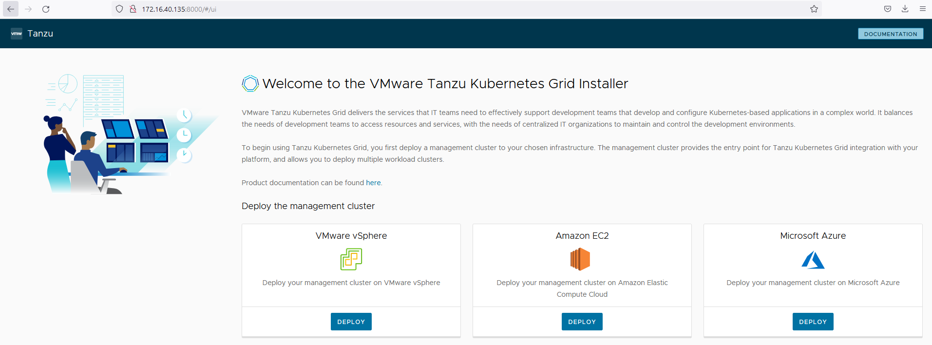
-
Click Deploy on the VMware vSphere tile
-
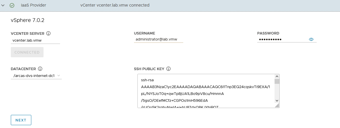
On the “IaaS Provider” section, enter the IP/FQDN and credentials of the vCenter server where the Tanzu Kubernetes Grid management cluster will be deployed
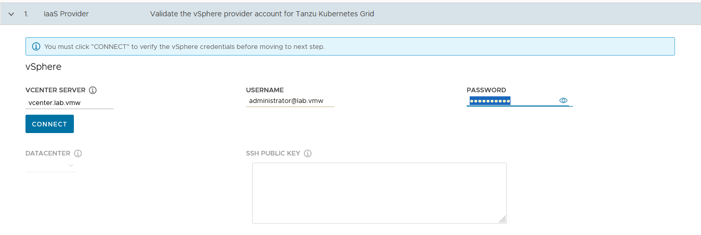
-
Click Connect and accept the vCenter Server SSL thumbprint
-
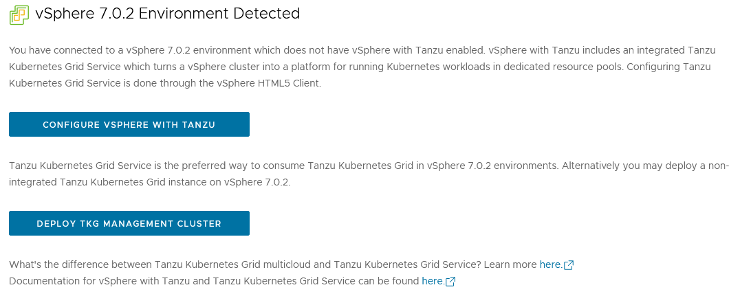
If you are running on a vCenter 7.x environment, you would get the following popup. Select “DEPLOY TKG MANAGEMENT CLUSTER” to continue.
-
Select the Datacenter and provide the SSH Public Key generated while configuring the Bootstrap VM .
If you have saved the SSH key in the default location, execute the following command in your bootstrap machine to get the SSH public key:
cat /root/.ssh/id_rsa.pub -
Click Next
-
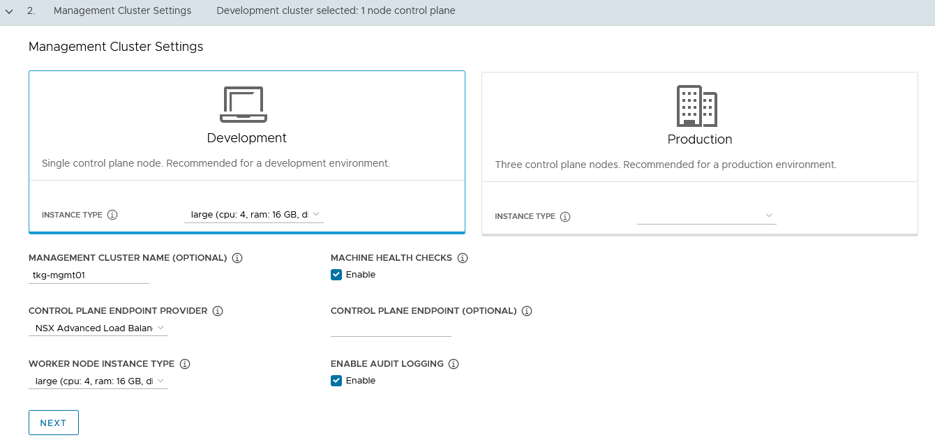
On the Management cluster settings section, provide the following details.
-
Based on your environment requirements, select the appropriate deployment type for the Tanzu Kubernetes Grid management cluster
-
Development: Recommended for Dev or POC environments
-
Production: Recommended for Production environments
-
-
VMware recommends that you set the instance type to Large or greater.
For the purpose of this document, the deployment type is Development and instance type is Large.
-
-
Management Cluster Name: Name for your management cluster.
-
Control Plane Endpoint Provider: Select NSX Advanced Load Balancer for the Control Plane HA.
-
Control Plane Endpoint: This field is optional. If left blank, NSX Advanced Load Balancer will assign an IP address from the
tkg_cluster_vip_pgpool created earlier.If you need to provide an IP address, pick an unused IP address from the
tkg_cluster_vip_pgstatic IP pools configured in AVI. -
Machine Health Checks: Enable
-
Enable Audit Logging: Enables audit logging for Kubernetes API server and node VMs. Set according to your environmental needs. For more information, see Audit Logging
-
Click Next
-
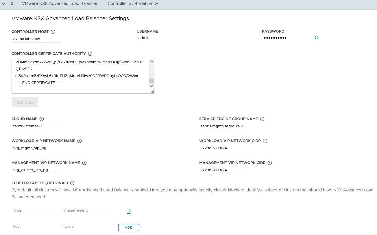
In the NSX Advanced Load Balancer section, provide the following:
-
Controller Host: NSX Advanced Load Balancer Controller IP/FQDN (Advanced Load Balancer Controller cluster IP/FQDN of the controller cluster is configured)
-
Controller credentials: Username and Password of NSX Advanced Load Balancer
-
Controller certificate
-
-
Click “Verify Credentials” and set the following parameters:
-
Cloud Name: Name of the cloud created while configuring NSX Advanced Load Balancer
tanzu-vcenter-01 -
Service Engine Group Name: Name of the Service Engine Group created for Tanzu Kubernetes Grid management clusters created while configuring NSX Advanced Load Balancer
tanzu-mgmt-segroup-01 -
Workload VIP Network Name: Select
tkg_mgmt_vip_pgas the TKG Management VIP/Data Network network and select the discovered subnet. -
Workload VIP network CIDR: Select the discovered subnet. In our example,
172.16.50.0/24 -
Management VIP network Name: Select
tkg_cluster_vip_pgas the TKG Cluster VIP/Data Network network. -
Cluster Labels: To adhere to the architecture, defining a label is mandatory. Provide the required labels, for example, type:management Note: Based on your requirements, you may specify multiple labels.
-
-
Click Next.
Important: With the above configurations, when Tanzu Kubernetes Grid clusters (shared service/workload) are tagged with the label
type=management, anakopod is deployed on the cluster. Any applications hosted on the cluster that require load balancing will be exposed via thetkg_mgmt_vip_pgnetwork, and the virtual service will be placed in thetanzu-mgmt-segroup-01SE group.As defined in the architecture, the Cluster Labels specified here will be applied only on shared service clusters.
If no labels are specified in the “Cluster Labels” section, an AKO pod is deployed on all clusters without any labeling requirement, which deviates from the defined architecture.
-
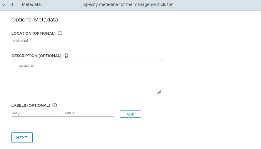
On the Metadata page, you can specify location and labels and click Next. These are optional.
-
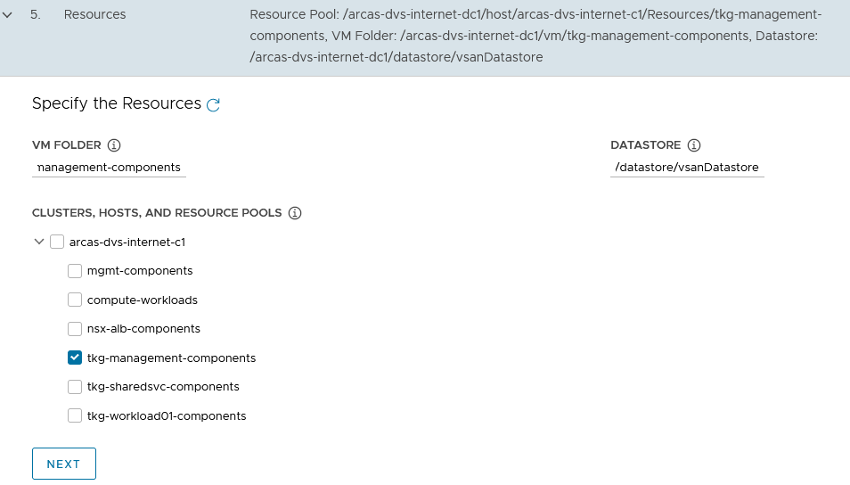
On the Resources section, specify the resources to be consumed by Tanzu Kubernetes Grid management cluster and click Next.
-
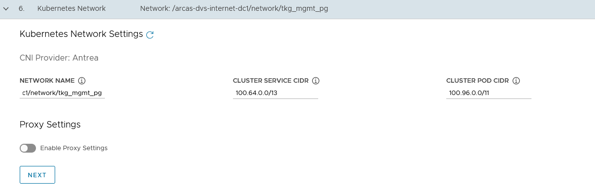
On the Kubernetes Network section, select the TKG Management Network (“tkg_mgmt_pg”) where the control plane and worker nodes will be placed during management cluster deployment. Ensure that the network has DHCP service enabled.
Optionally, change the Pod and Service CIDR if the default provided network is already in use in your environment.
-
If the Tanzu environment is placed behind a proxy, enable the proxy and provide the proxy details. If using a proxy, the following details are the key points:
- If you set http-proxy, you must also set https-proxy and vice-versa.
-
For the no-proxy section:
-
For Tanzu Kubernetes Grid management and workload clusters, localhost, 127.0.0.1, the values of CLUSTER_CIDR and SERVICE_CIDR, .svc, and .svc.cluster.local values are appended along with the user-specified values.
-
Important: If the Kubernetes cluster needs to communicate with external services and infrastructure endpoints in your Tanzu Kubernetes Grid environment, ensure that those endpoints are reachable by your proxies or add them to TKG_NO_PROXY. Depending on your environment configuration, this may include, but is not limited to, your OIDC or LDAP server, Harbor, NSX-T, and NSX Advanced Load Balancer, and vCenter.
-
For vSphere, you must manually add the CIDR of the TKG Management Network and Cluster VIP networks which includes the IP address of your control plane endpoints, to TKG_NO_PROXY.
-
-
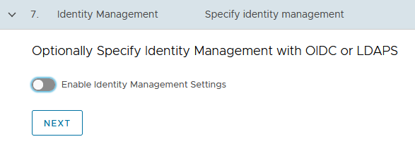
Optionally, specify Identity Management with OIDC or LDAPs - This is not covered in this document and will be documented separately. For the purpose of this document, identity management integration has been deactivated .
-
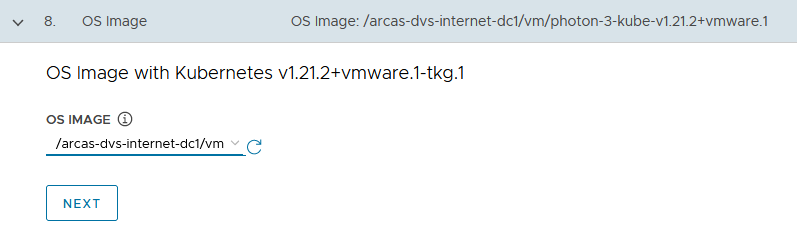
Select the OS image that will be used for the management cluster deployment. Note: This list will appear empty if you don’t have a compatible template present in your environment. See the steps provided in Import Base Image template for TKG Cluster deployment.
-
Register Tanzu Mission Control: Registering Tanzu Kubernetes Grid management clusters with Tanzu Mission Control allows you to provision and manage Tanzu Kubernetes clusters by using the Tanzu Mission Control dashboard interface..
-
Check the Participate in the Customer Experience Improvement Program, if you so desire and click Review Configuration
-
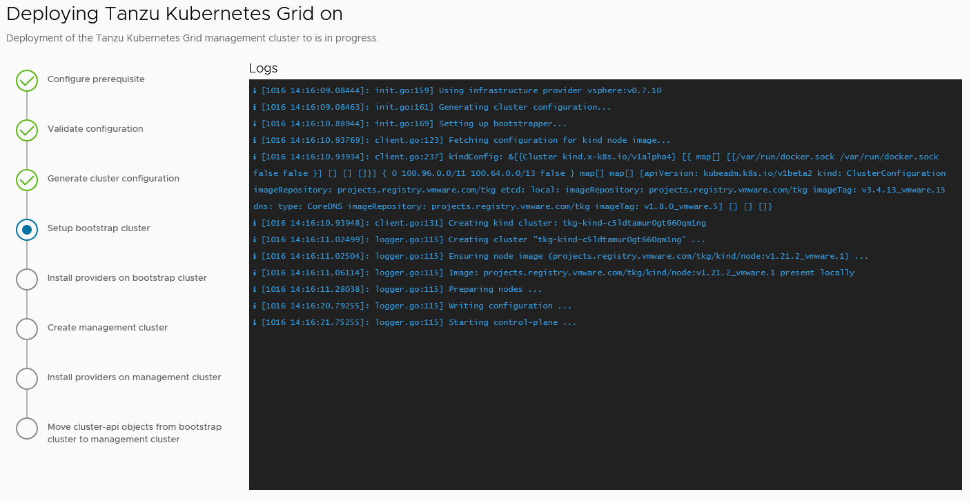
Review the entire configuration. After reviewing it, you can either copy the command provided and execute it on the CLI or proceed with UI to Deploy Management Cluster.
When the deployment is triggered from the UI, the installer wizard displays the deployment logs on the screen.
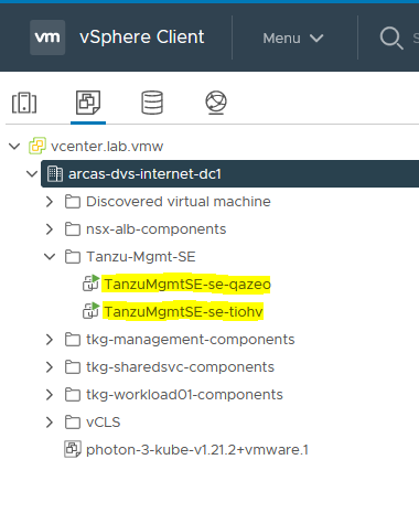
While the cluster is being deployed, you will find that a virtual service will be created in NSX Advanced Load Balancer and new service engines will be deployed in vCenter by NSX Advanced Load Balancer. The service engines will be mapped to the SE Group tanzu-mgmt-segroup-01.
Behind the scenes when the Tanzu Kubernetes Grid management cluster is being deployed:
-
NSX Advanced Load Balancer service engines are deployed in vCenter. This task is orchestrated by the NSX Advanced Load Balancer controller.
-
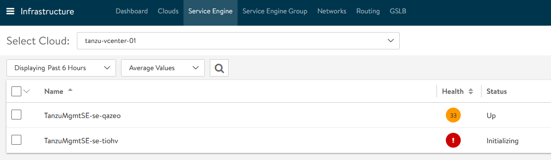
Service engine status in NSX Advanced Load Balancer: The following snippet shows that the first service engine has been initialized successfully and the second service engine is initializing.
-
Service Engine Group Status in NSX Advanced Load Balancer: In our configuration, the virtual service required for the Tanzu Kubernetes Grid clusters control plane High Availability (HA) will be hosted on the
tgk-mgmt-segroup-01service engine group.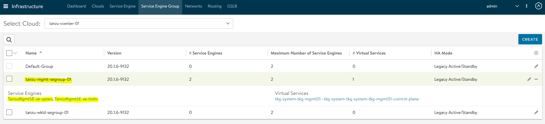
-
Virtual Service status in NSX Advanced Load Balancer
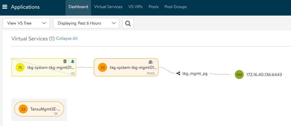
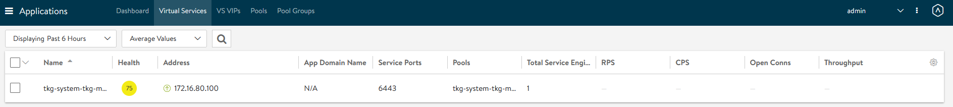
The virtual service health is impacted because the second service engine is still being initialized; you can ignore this.
-
After the Tanzu Kubernetes Grid management cluster is successfully deployed, you will see this in the Tanzu Bootstrap UI:
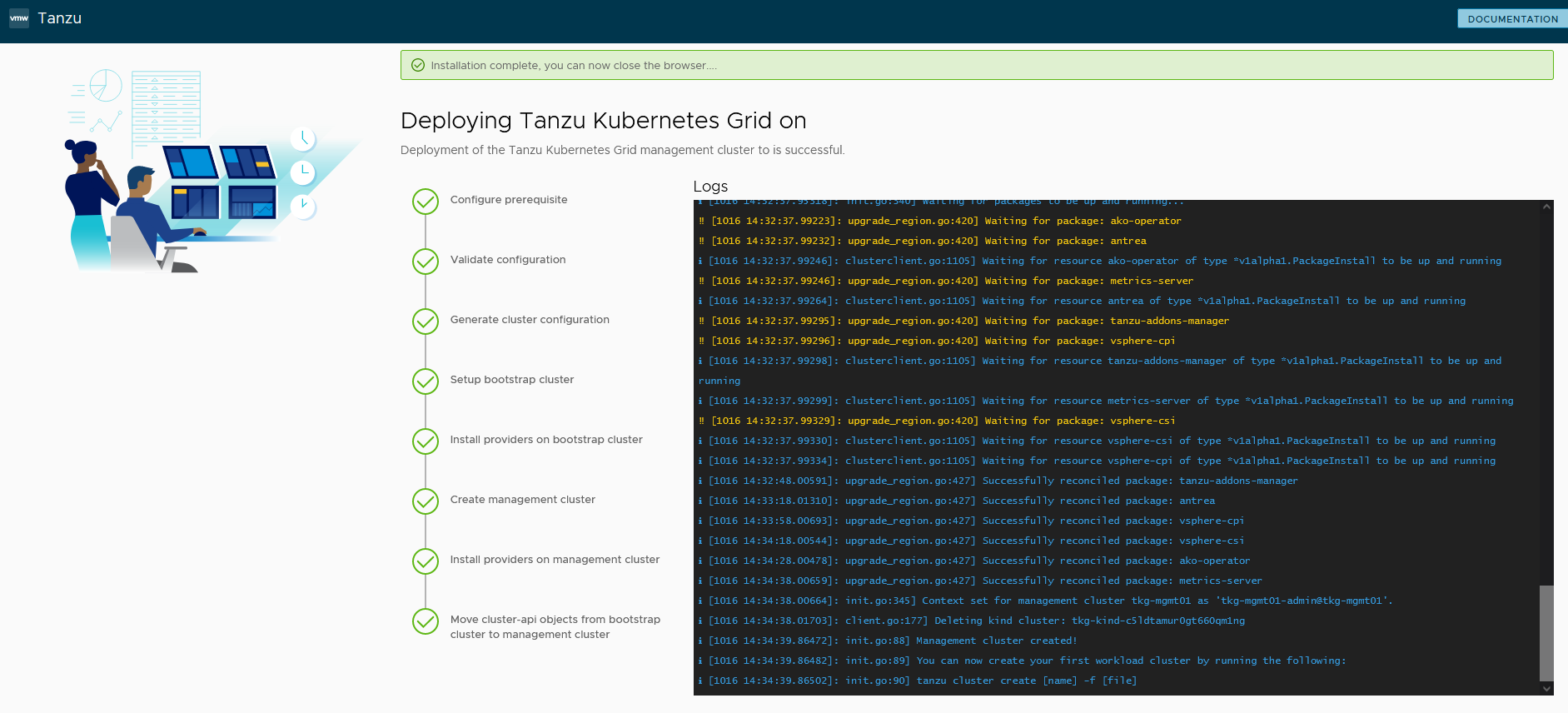
-
The installer will automatically set the context to the Tanzu Kubernetes Grid management cluster in the bootstrap machine.
Now you can access the Tanzu Kubernetes Grid management cluster from the bootstrap machine and perform additional tasks, such as verifying the management cluster health and deploying the workload clusters.
To get the status of Tanzu Kubernetes Grid management cluster, execute the following command:
tanzu management-cluster get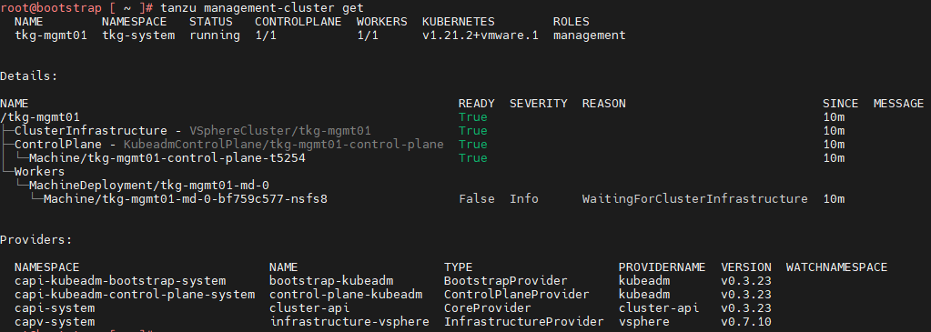
-
Use
kubectlto get the status of the Tanzu Kubernetes Grid management cluster nodes
The Tanzu Kubernetes Grid management cluster is successfully deployed. Now you can create shared service and workload clusters.
Deploy Tanzu Kubernetes Grid Shared Service Cluster
Each Tanzu Kubernetes Grid instance can have only one shared services cluster. Create a shared services cluster if you intend to deploy Harbor.
Deploying a shared service cluster is exactly the same as deploying a workload cluster, except that you will add the tanzu-services label to the shared services cluster as its cluster role. This label identifies the shared services cluster to the management cluster and workload clusters. Another major difference between shared service clusters and workload clusters is that the “Cluster Labels” that were defined while deploying the management cluster will be applied to shared service clusters. This is to ensure that only shared service clusters will make use of the TKG Cluster VIP/Data Network for application load balancing and that virtual services are deployed on “Service Engine Group 1”.
In order to deploy a shared service cluster, you need to create a cluster config file in which you specify options to connect the shared service cluster to the vCenter server and to identify the vSphere resources that the cluster will use. You can also specify standard sizes for the control plane and worker node VMs, or configure the CPU, memory, and disk sizes for control plane and worker nodes explicitly. If you use custom image templates, you can identify which template to use to create node VMs.
The following sample file includes the minimum required configurations. For information about all configuration file variables, see the Tanzu CLI Configuration File Variable Reference. Modify the parameters according to your requirements.
CLUSTER_CIDR: 100.96.0.0/11
SERVICE_CIDR: 100.64.0.0/13
CLUSTER_PLAN: <prod/dev>
ENABLE_CEIP_PARTICIPATION: 'true'
ENABLE_MHC: 'true'
IDENTITY_MANAGEMENT_TYPE: none
INFRASTRUCTURE_PROVIDER: vsphere
TKG_HTTP_PROXY_ENABLED: 'false'
AVI_CONTROL_PLANE_HA_PROVIDER: "true"
CLUSTER_NAME: <Provide a Name For the TKG Cluster>
DEPLOY_TKG_ON_VSPHERE7: 'true'
VSPHERE_DATACENTER: /<DC-Name>
VSPHERE_DATASTORE: /<DC-Name>/datastore/<Datastore-Name>
VSPHERE_FOLDER: /<DC-Name>/vm/<Folder_Name>
VSPHERE_NETWORK: /<DC-Name>/network/<Network-Name>
VSPHERE_RESOURCE_POOL: /<DC-Name>/host/<Cluster-Name>/Resources/<Resource-Pool-Name>
VSPHERE_SERVER: <vCenter-Address>
VSPHERE_SSH_AUTHORIZED_KEY: "ssh-rsa Nc2EA [...] h2X8uPYqw== [email protected]"
VSPHERE_USERNAME: <vCenter-SSO-Username>
VSPHERE_PASSWORD: <SSO-User-Password>
VSPHERE_TLS_THUMBPRINT: <vCenter Server Thumbprint>
ENABLE_AUDIT_LOGGING: true/false
ENABLE_DEFAULT_STORAGE_CLASS: true/false
ENABLE_AUTOSCALER: true/false
CONTROLPLANE_SIZE: small/medium/large/extra-large
WORKER_SIZE: small/medium/large/extra-large
WORKER_MACHINE_COUNT: <number of worker nodes to be deployed>
Key considerations when creating your Shared Service cluster config file:
| Variables | Value |
|---|---|
CLUSTER_PLAN |
prod : For all production deployments dev: for POC/Dev environments |
IDENTITY_MANAGEMENT_TYPE |
Match the value set for the management cluster, oidc, ldap, or none. Note: You do not need to configure additional OIDC or LDAP settings in the configuration file for workload clusters |
TKG_HTTP_PROXY_ENABLED |
true/false If true, the following additional variables needs to be provided TKG_HTTP_PROXYTKG_HTTPS_PROXYTKG_NO_PROXY |
VSPHERE_NETWORK |
As per the architecture, TKG Shared service cluster has dedicated overlay segment (tkg-ss-segment) |
CONTROLPLANE_SIZE & WORKER_SIZE |
Consider extra-large, as Harbor will be deployed on this cluster and this cluster may be attached to TMC and TO. To define a custom size, remove the CONTROLPLANE_SIZE and WORKER_SIZE variables from the config file and add the following variables with the required resource allocation.For Control Plane Nodes: VSPHERE_CONTROL_PLANE_NUM_CPUSVSPHERE_CONTROL_PLANE_MEM_MIBVSPHERE_CONTROL_PLANE_DISK_GIBFor Worker Nodes: VSPHERE_WORKER_NUM_CPUS
VSPHERE_WORKER_MEM_MIB
VSPHERE_WORKER_DISK_GIB
|
VSPHERE_CONTROL_PLANE_ENDPOINT |
This is optional. If left blank, NSX ALB will assign an IP address from the tkg-cluster-vip-segment pool created earlier.If you need to provide an IP address, pick an unused address from the “TKG Cluster VIP/Data Network” static IP pools configured in NSX ALB. |
The following is the modified Tanzu Kubernetes Grid shared service config file:
CLUSTER_CIDR: 100.96.0.0/11
SERVICE_CIDR: 100.64.0.0/13
CLUSTER_PLAN: dev
ENABLE_CEIP_PARTICIPATION: 'true'
ENABLE_MHC: 'true'
IDENTITY_MANAGEMENT_TYPE: none
INFRASTRUCTURE_PROVIDER: vsphere
TKG_HTTP_PROXY_ENABLED: 'false'
AVI_CONTROL_PLANE_HA_PROVIDER: "true"
CLUSTER_NAME: tkg-shared-svc
DEPLOY_TKG_ON_VSPHERE7: 'true'
VSPHERE_DATACENTER: /arcas-dvs-internet-dc1
VSPHERE_DATASTORE: /arcas-dvs-internet-dc1/datastore/vsanDatastore
VSPHERE_FOLDER: /arcas-dvs-internet-dc1/vm/tkg-sharedsvc-components
VSPHERE_NETWORK: /arcas-dvs-internet-dc1/network/tkg-ss-segment
VSPHERE_RESOURCE_POOL: /arcas-dvs-internet-dc1/host/arcas-dvs-internet-c1/Resources/tkg-sharedsvc-components
VSPHERE_SERVER: vcenter.lab.vmw
VSPHERE_SSH_AUTHORIZED_KEY: ssh-rsa AAAAB3NzaC1yc2EAAAADAQABAAACAQC6l1Tnp3EQ24cqskvTi9EXA/1pL/NYSJoT0q+qwTp8jUA1LBo9pV8cu/HmnnA/5gsO/OEefMCfz+CGPOo1mH596EdA/rUQo5K2rqhuNwlA+i+hU87dxQ8KJYhjPOT/lGHQm8VpzNQrF3b0Cq5WEV8b81X/J+H3i57ply2BhC3BE7B0lKbuegnb5aaqvZC+Ig97j1gt5riV/aZg400c3YGJl9pmYpMbyEeJ8xd86wXXyx8X1xp6XIdwLyWGu6zAYYqN4+1pqjV5IBovu6M6rITS0DlgFEFhihZwXxCGyCpshSM2TsIJ1uqdX8zUlhlaQKyAt+2V29nnHDHG1WfMYQG2ypajmE1r4vOkS+C7yUbOTZn9sP7b2m7iDnCG0GvCUT+lNQy8WdFC/Gm0V6+5DeBY790y1NEsl+9RSNNL+MzT/18Yqiq8XIvwT2qs7d5GpSablsITBUNB5YqXNEaf76ro0fZcQNAPfZ67lCTlZFP8v/S5NExqn6P4EHht0m1hZm1FhGdY7pQe8dLz/74MLTEQlP7toOp2ywoArYno8cFVl3PT8YR3TVQARvkS2pfNOquc5iU0r1FXOCrEc3d+LvJYmalmquvghZjblvxQKwguLFIodzdO/3CcpJvwGg0PiANvYZRqVNfTDCjtrN+lFXurlm2pSsA+YI5cbRtZ1ADaPw== [email protected]
VSPHERE_USERNAME: [email protected]
VSPHERE_PASSWORD: VMware@123
VSPHERE_TLS_THUMBPRINT: 40:1E:6D:30:4C:72:A6:8E:9D:AE:A8:67:DE:DA:C9:CA:B3:A6:C6:C2
ENABLE_AUDIT_LOGGING: true
ENABLE_DEFAULT_STORAGE_CLASS: true
ENABLE_AUTOSCALER: false
CONTROLPLANE_SIZE: large
WORKER_SIZE: extra-large
WORKER_MACHINE_COUNT: 1
After creating the cluster configuration file, execute the following command to initiate the cluster deployment:
tanzu cluster create -f <path-to-config.yaml> -v 6
When the cluster is successfully deployed, you will see the following results: 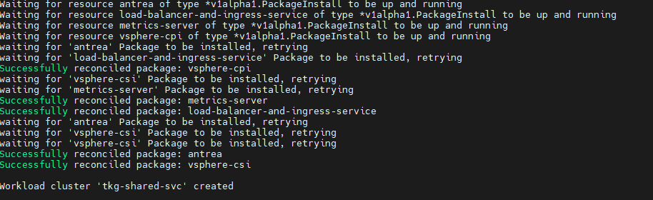
Now, connect to the Tanzu management cluster context and apply the following labels:
## Add the tanzu-services label to the shared services cluster as its cluster role. In the following command, “tkg-shared-svc” is the name of the shared service cluster.
kubectl label cluster.cluster.x-k8s.io/tkg-shared-svc cluster-role.tkg.tanzu.vmware.com/tanzu-services="" --overwrite=true

## Tag shared service cluster with all “Cluster Labels” defined while deploying the management cluster. Once the “Cluster Labels” are applied, the AKO pod will be deployed on the Shared Service Cluster.
kubectl label cluster tkg-shared-svc type=management
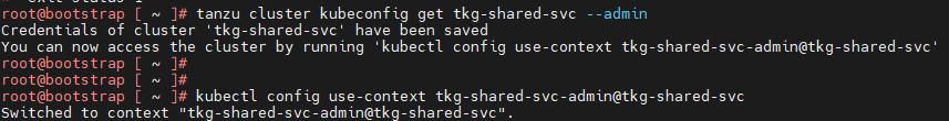
Get the admin context of the shared service cluster using the following commands and switch the context to the Shared Service cluster:
## Use the following command to get the admin context of Shared Service Cluster. In this command, “tkg-shared-svc” is the name of the shared service cluster.
<_Added line break above. Is this correct?_>
tanzu cluster kubeconfig get tkg-shared-svc --admin
## Use the following to use the context of Shared Service Cluster
kubectl config use-context tkg-shared-svc-admin@tkg-shared-svc
After the shared service cluster is successfully created, you are ready to deploy the Harbor package. See Deploy User-Managed Packages on Tanzu Kubernetes Grid Clusters.
You must ensure that the “cert-manager” and “contour” user packages are installed before deploying Harbor. Deploy in the following order:
Deploy Tanzu Kubernetes Grid Workload Clusters
In order to deploy a workload cluster, you need to create a cluster config file in which you specify options for connecting to vCenter Server and for identifying the vSphere resources that the cluster will use.
You can also specify standard sizes for the control plane and worker node VMs, or you can configure the CPU, memory, and disk sizes for control plane and worker nodes explicitly. If you use custom image templates, you can identify which template to use to create node VMs.
As per the architecture, workload clusters make use of a separate SE group (Service Engine Group 2) and VIP Network (TKG Workload VIP/Data Network) for application load balancing. You can control the SE group by creating a new AKODeploymentConfig. For more details, see Create and deploy AKO Deployment Config for Tanzu Kubernetes Grid Workload Cluster
The following sample cluster config file includes the minimum required configuration parameters to create a Tanzu Kubernetes Grid workload cluster. To learn about all configuration file parameters, see the Tanzu CLI Configuration File Variable Reference. Modify the config file according to your requirements.
CLUSTER_CIDR: 100.96.0.0/11
SERVICE_CIDR: 100.64.0.0/13
CLUSTER_PLAN: <prod/dev>
ENABLE_CEIP_PARTICIPATION: 'true'
ENABLE_MHC: 'true'
IDENTITY_MANAGEMENT_TYPE: none
INFRASTRUCTURE_PROVIDER: vsphere
TKG_HTTP_PROXY_ENABLED: 'false'
AVI_CONTROL_PLANE_HA_PROVIDER: "true"
CLUSTER_NAME: <Provide a Name For the TKG Cluster>
DEPLOY_TKG_ON_VSPHERE7: 'true'
VSPHERE_DATACENTER: /<DC-Name>
VSPHERE_DATASTORE: /<DC-Name>/datastore/<Datastore-Name>
VSPHERE_FOLDER: /<DC-Name>/vm/<Folder_Name>
VSPHERE_NETWORK: /<DC-Name>/network/<Network-Name>
VSPHERE_RESOURCE_POOL: /<DC-Name>/host/<Cluster-Name>/Resources/<Resource-Pool-Name>
VSPHERE_SERVER: <vCenter-Address>
VSPHERE_SSH_AUTHORIZED_KEY: "ssh-rsa Nc2EA [...] h2X8uPYqw== [email protected]"
VSPHERE_USERNAME: <vCenter-SSO-Username>
VSPHERE_PASSWORD: <SSO-User-Password>
VSPHERE_TLS_THUMBPRINT: <vCenter Server Thumbprint>
ENABLE_AUDIT_LOGGING: true/false
ENABLE_DEFAULT_STORAGE_CLASS: true/false
ENABLE_AUTOSCALER: true/false
CONTROLPLANE_SIZE: small/medium/large/extra-large
WORKER_SIZE: small/medium/large/extra-large
WORKER_MACHINE_COUNT: <# of worker nodes to be deployed>
Key considerations when creating workload cluster config files:
| Variables | Value |
|---|---|
CLUSTER_PLAN |
prod : For all production deployments dev: for POC/Dev environments |
IDENTITY_MANAGEMENT_TYPE |
Match the value set for the management cluster, oidc, ldap, or none. Note: You do not need to configure additional OIDC or LDAP settings in the workload cluster configuration file. |
TKG_HTTP_PROXY_ENABLED |
true/false If true, the following additional variables need to be provided/ TKG_HTTP_PROXYTKG_HTTPS_PROXYTKG_NO_PROXY |
VSPHERE_NETWORK |
As per the architecture, the TKG workload cluster will be attached to “TKG Workload Network”. Note: The architecture supports multiple TKG workload clusters on the same network and/or separate networks for each workload cluster. |
CONTROLPLANE_SIZE & WORKER_SIZE |
Consider setting this to extra-large, as Harbor will be deployed on this cluster and this cluster may be attached to TMC and TO. To define custom sizes, remove the CONTROLPLANE_SIZE and WORKER_SIZE variables from the config file and add the following variables with required resource allocationFor Control Plane Nodes: VSPHERE_CONTROL_PLANE_NUM_CPUSVSPHERE_CONTROL_PLANE_MEM_MIBVSPHERE_CONTROL_PLANE_DISK_GIBFor Worker Nodes: VSPHERE_WORKER_NUM_CPUSVSPHERE_WORKER_MEM_MIBVSPHERE_WORKER_DISK_GIB |
VSPHERE_CONTROL_PLANE_ENDPOINT |
This is optional; if left blank, NSX ALB will assign an IP address from the tkg-cluster-vip-segment pool created earlier.If you need to provide an IP address, pick an unused address from the “TKG Cluster VIP/Data Network” static IP pools configured in NSX ALB. |
ENABLE_AUTOSCALER |
This is an optional parameter. Set if you want to override the default value. The default value is false; if set to true, you must include the following additional variables:AUTOSCALER_MAX_NODES_TOTALAUTOSCALER_SCALE_DOWN_DELAY_AFTER_ADDAUTOSCALER_SCALE_DOWN_DELAY_AFTER_DELETEAUTOSCALER_SCALE_DOWN_DELAY_AFTER_FAILUREAUTOSCALER_SCALE_DOWN_UNNEEDED_TIMEAUTOSCALER_MAX_NODE_PROVISION_TIMEAUTOSCALER_MIN_SIZE_0AUTOSCALER_MAX_SIZE_0For more details see Cluster Autoscaler |
| WORKER_MACHINE_COUNT | Consider setting the value to 3 or above if the cluster needs to be part of Tanzu Service Mesh (TSM) |
The modified Tanzu Kubernetes Grid shared service config file is as follows:
CLUSTER_CIDR: 100.96.0.0/11
SERVICE_CIDR: 100.64.0.0/13
CLUSTER_PLAN: dev
ENABLE_CEIP_PARTICIPATION: 'true'
ENABLE_MHC: 'true'
IDENTITY_MANAGEMENT_TYPE: none
INFRASTRUCTURE_PROVIDER: vsphere
TKG_HTTP_PROXY_ENABLED: 'false'
AVI_CONTROL_PLANE_HA_PROVIDER: "true"
CLUSTER_NAME: tkg-workload-dev
DEPLOY_TKG_ON_VSPHERE7: 'true'
VSPHERE_DATACENTER: /arcas-dvs-internet-dc1
VSPHERE_DATASTORE: /arcas-dvs-internet-dc1/datastore/vsanDatastore
VSPHERE_FOLDER: /arcas-dvs-internet-dc1/vm/tkg-workload01-components
VSPHERE_NETWORK: /arcas-dvs-internet-dc1/network/tkg-workload-segment
VSPHERE_RESOURCE_POOL: /arcas-dvs-internet-dc1/host/arcas-dvs-internet-c1/Resources/tkg-workload01-components
VSPHERE_SERVER: vcenter.lab.vmw
VSPHERE_SSH_AUTHORIZED_KEY: ssh-rsa AAAAB3NzaC1yc2EAAAADAQABAAACAQC6l1Tnp3EQ24cqskvTi9EXA/1pL/NYSJoT0q+qwTp8jUA1LBo9pV8cu/HmnnA/5gsO/OEefMCfz+CGPOo1mH596EdA/rUQo5K2rqhuNwlA+i+hU87dxQ8KJYhjPOT/lGHQm8VpzNQrF3b0Cq5WEV8b81X/J+H3i57ply2BhC3BE7B0lKbuegnb5aaqvZC+Ig97j1gt5riV/aZg400c3YGJl9pmYpMbyEeJ8xd86wXXyx8X1xp6XIdwLyWGu6zAYYqN4+1pqjV5IBovu6M6rITS0DlgFEFhihZwXxCGyCpshSM2TsIJ1uqdX8zUlhlaQKyAt+2V29nnHDHG1WfMYQG2ypajmE1r4vOkS+C7yUbOTZn9sP7b2m7iDnCG0GvCUT+lNQy8WdFC/Gm0V6+5DeBY790y1NEsl+9RSNNL+MzT/18Yqiq8XIvwT2qs7d5GpSablsITBUNB5YqXNEaf76ro0fZcQNAPfZ67lCTlZFP8v/S5NExqn6P4EHht0m1hZm1FhGdY7pQe8dLz/74MLTEQlP7toOp2ywoArYno8cFVl3PT8YR3TVQARvkS2pfNOquc5iU0r1FXOCrEc3d+LvJYmalmquvghZjblvxQKwguLFIodzdO/3CcpJvwGg0PiANvYZRqVNfTDCjtrN+lFXurlm2pSsA+YI5cbRtZ1ADaPw== [email protected]
VSPHERE_USERNAME: [email protected]
VSPHERE_PASSWORD: VMware@123
VSPHERE_TLS_THUMBPRINT: 40:1E:6D:30:4C:72:A6:8E:9D:AE:A8:67:DE:DA:C9:CA:B3:A6:C6:C2
ENABLE_AUDIT_LOGGING: true
ENABLE_DEFAULT_STORAGE_CLASS: true
ENABLE_AUTOSCALER: false
CONTROLPLANE_SIZE: large
WORKER_SIZE: extra-large
WORKER_MACHINE_COUNT: 3
After preparing the cluster configuration file, execute the following command to initiate the cluster deployment:
tanzu cluster create -f <path-to-config.yaml> -v 6
Once the cluster is successfully deployed, you will see the following results: 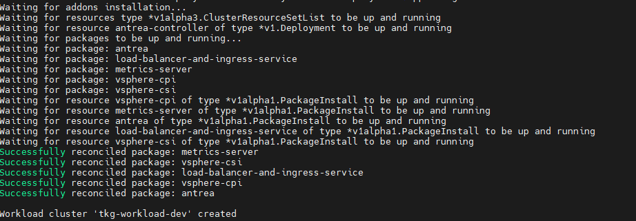
Configure NSX Advanced Load Balancer in Tanzu Kubernetes Grid Workload Cluster
Tanzu Kubernetes Grid management clusters with NSX Advanced Load Balancer have a default AKODeploymentConfig that is deployed during installation. It is called install-ako-for-all.
By default, any clusters that match the cluster labels defined in install-ako-for-all will reference this file for their virtual IP networks, service engine (SE) groups, and L7 ingress. As part of our architecture, only shared service cluster makes use of the configuration defined in the default AKODeploymentConfig install-ako-for-all.
As per the defined architecture, workload clusters must not make use of Service Engine Group 1 and VIP Network TKG Cluster VIP/Data Network for application load balancer services**. **A separate SE group (Service Engine Group 2) and VIP Network (TKG Workload VIP/Data Network) will be used by the workload clusters, These configurations can be enforced on workload clusters by:
-
Creating a new AKODeploymentConfig in the Tanzu Kubernetes Grid management cluster. This AKODeploymentConfig file dictates which specific SE group and VIP network that the workload clusters can use for load balancing.
-
Apply the new AKODeploymentConfig: Label the workload cluster to match the AKODeploymentConfig.spec.clusterSelector.matchLabels element in the AKODeploymentConfig file. Once the labels are applied on the workload cluster, Tanzu Kubernetes Grid management cluster will deploy the AKO pod on the target workload cluster that has the configuration defined in the new AKODeploymentConfig.
The following is the format of the AKODeploymentConfig yaml file.
apiVersion: networking.tkg.tanzu.vmware.com/v1alpha1
kind: AKODeploymentConfig
metadata:
  finalizers:
    - ako-operator.networking.tkg.tanzu.vmware.com
  generation: 2
  name: <Unique name of AKODeploymentConfig>
spec:
  adminCredentialRef:
    name: avi-controller-credentials
    namespace: tkg-system-networking
  certificateAuthorityRef:
    name: avi-controller-ca
    namespace: tkg-system-networking
  cloudName: <NAME OF THE CLOUD>
  clusterSelector:
    matchLabels:
      <KEY>: <VALUE>
  controller: <NSX ALB CONTROLLER IP/FQDN>
  dataNetwork:
    cidr: <VIP NETWORK CIDR>
    name: <VIP NETWORK NAME>
  extraConfigs:
    image:
      pullPolicy: IfNotPresent
      repository: projects.registry.vmware.com/tkg/ako
      version: v1.3.2_vmware.1
    ingress:
      defaultIngressController: false
      disableIngressClass: true
  serviceEngineGroup: <SERVICE ENGINE NAME>
The following is a sample AKODeploymentConfig file with sample values in place. In this example, the Tanzu Kubernetes Grid management cluster will deploy AKO pod on any workload cluster that matches the label type=workloadset01. The AKO configuration will be as follows:
-
cloud:
tanzu-vcenter-01 -
service engine Group:
tanzu-wkld-segroup-01 -
VIP/data network:
tkg-cluster-vip-segment
apiVersion: networking.tkg.tanzu.vmware.com/v1alpha1
kind: AKODeploymentConfig
metadata:
  finalizers:
    - ako-operator.networking.tkg.tanzu.vmware.com
  generation: 2
  name: tanzu-ako-workload-set01
spec:
  adminCredentialRef:
    name: avi-controller-credentials
    namespace: tkg-system-networking
  certificateAuthorityRef:
    name: avi-controller-ca
    namespace: tkg-system-networking
  cloudName: tanzu-vcenter-01
  clusterSelector:
    matchLabels:
      type: workloadset01
  controller: avi-ha.lab.vmw
  dataNetwork:
    cidr: tkg-workload-vip-segment
    name: 172.16.70.0/24
  extraConfigs:
    image:
      pullPolicy: IfNotPresent
      repository: projects.registry.vmware.com/tkg/ako
      version: v1.3.2_vmware.1
    ingress:
      defaultIngressController: false
      disableIngressClass: true
  serviceEngineGroup: tanzu-wkld-segroup-01
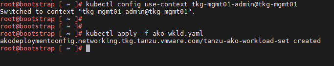
Once you have the AKO configuration file ready, use the kubectl command to set the context to Tanzu Kubernetes Grid management cluster. Use the following command to list the available AKODeploymentConfig:
kubectl apply -f <path_to_akodeploymentconfig.yaml>
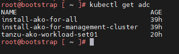
Use the following command to list all AKODeploymentConfig created under the management cluster:
kubectl get adc or kubectl get akodeploymentconfig
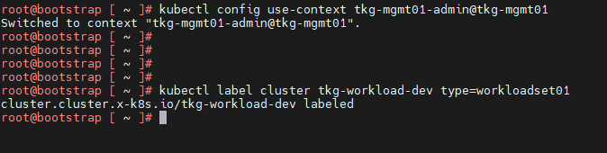
Now that you have successfully created the AKO deployment config, you need to apply the cluster labels defined in the AKODeploymentConfig to any of the Tanzu Kubernetes Grid workload clusters. Once the labels are applied, the Tanzu Kubernetes Grid management cluster will deploy the AKO pod on the target workload cluster.
kubectl label cluster <cluster name>\<label>
Connect to Tanzu Kubernetes Grid Workload Cluster and Validate the Deployment
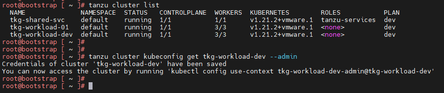
Now that the Tanzu Kubernetes Grid workload cluster is created and the required AKO configurations are applied, use the following command to get the admin context of the Tanzu Kubernetes Grid workload cluster.
tanzu cluster kubeconfig get <cluster-name> --admin
Now connect to the Tanzu Kubernetes Grid workload cluster using the kubectl command and run the following commands to check the status of AKO and other components:
kubectl get nodes # List all nodes with status
kubectl get pods -n avi-system # To check the status of AKO pod
kubectl get pods -A # Lists all pods and its status
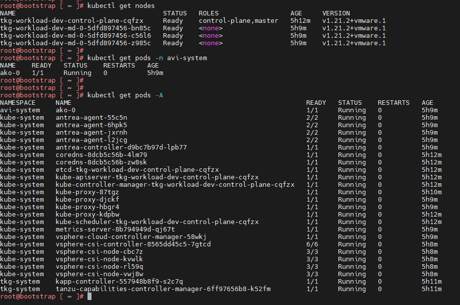
You can see that the workload cluster is successfully deployed and AKO pod is deployed on the cluster. You can now configure SaaS services for the cluster and/or deploy user managed packages on this cluster.
Deploy User-Managed Packages on Tanzu Kubernetes Grid Clusters
Tanzu Kubernetes Grid includes the following user-managed packages. These packages provide in-cluster and shared services to the Kubernetes clusters that are running in your Tanzu Kubernetes Grid environment.
| Function | Package | Location |
|---|---|---|
| Certificate Management | cert-manager | Workload or shared services cluster |
| Container networking | multus-cni | Workload cluster |
| Container registry | harbor | Shared services cluster |
| Ingress control | contour | Workload or shared services cluster |
| Log forwarding | fluent-bit | Workload cluster |
| Monitoring | grafana prometheus |
Workload cluster |
| Service discovery | external-dns | Workload or shared services cluster |
Install Cert-Manager User Package
Cert-Manager is required for the Contour, Harbor, Prometheus, and Grafana packages.
-
Switch the context to the respective cluster and capture the available Cert-Manager version
tanzu package available list cert-manager.tanzu.vmware.com -A -
Install the Cert-Manager package.
tanzu package install cert-manager --package-name cert-manager.tanzu.vmware.com --namespace cert-manager --version <AVAILABLE-PACKAGE-VERSION> --create-namespace -
Validate the Cert-Manager package installation. The status must change to “Reconcile succeeded”
tanzu package installed list -A | grep cert-manager
Install the Contour User Package
Contour is required for the Harbor, Prometheus, and Grafana packages.
-
Switch context to the respective cluster, and ensure that the AKO pod is in a running state.
kubectl get pods -A | grep ako -
Create the following configuration file named contour-data-values.yaml.
--- infrastructure_provider: vsphere namespace: tanzu-system-ingress contour: configFileContents: {} useProxyProtocol: false replicas: 2 pspNames: "vmware-system-restricted" logLevel: info envoy: service: type: LoadBalancer annotations: {} nodePorts: http: null https: null externalTrafficPolicy: Cluster disableWait: false hostPorts: enable: true http: 80 https: 443 hostNetwork: false terminationGracePeriodSeconds: 300 logLevel: info pspNames: null certificates: duration: 8760h renewBefore: 360h -
Use the following command to capture the available Contour version:
tanzu package available list contour.tanzu.vmware.com -A -
Install the Contour Package
tanzu package install contour --package-name contour.tanzu.vmware.com --version <AVAILABLE-PACKAGE-VERSION> --values-file <path_to_contour-data-values.yaml_file> --namespace tanzu-system-contour --create-namespace -
Validate the Contour package installation. The status must change to “Reconcile succeeded”.
tanzu package installed list -A | grep contour
Install Harbor User Package
In order to install Harbor, ensure that Cert-Manager and Contour user packages are installed on the cluster.
-
Check if the prerequisite packages are installed on the cluster
tanzu package installed list -AEnsure that the status of
cert-managerandcontouris “Reconcile succeeded”. -
Capture the available Harbor version
tanzu package available list harbor.tanzu.vmware.com -A -
Obtain the “harbor-data-values.yaml” file
image_url=$(kubectl -n tanzu-package-repo-global get packages harbor.tanzu.vmware.com.<package version> -o jsonpath='{.spec.template.spec.fetch[0].imgpkgBundle.image}') imgpkg pull -b $image_url -o /tmp/harbor-package cp /tmp/harbor-package/config/values.yaml <path to save harbor-data-values.yaml> -
Set the mandatory passwords and secrets in the
harbor-data-values.yamlfile.bash /tmp/harbor-package/config/scripts/generate-passwords.sh ./harbor-data-values.yaml -
Update the following sections and remove comments in the harbor-data-values.yaml file.
##Update required fields hostname: <Harbor Registry FQDN> tls.crt: <Full Chain cert> (Optional, only if provided) tls.key: <Cert Key> (Optional, only if provided) ##Delete the auto generated password and replace it with the user provided value harborAdminPassword: <Set admin password> ## Remove all comments in the harbor-data-values.yaml file: yq -i eval '... comments=""' ./harbor-data-values.yaml -
Install the Harbor Package using the following command:
tanzu package install harbor --package-name harbor.tanzu.vmware.com --version <available package version> --values-file <path to harbor-data-values.yaml> --namespace tanzu-system-registry --create-namespace -
To address a known issue, patch the Harbor package by following the steps in the Knowledge Base article: The harbor-notary-signer pod fails to start
-
Confirm that the harbor package has been installed. The status must change to “Reconcile succeeded”.
tanzu package installed list -A | grep harbor
Configure SaaS Services
The following VMware SaaS services provide additional Kubernetes lifecycle management, observability, and service mesh features.
- Tanzu Mission Control (TMC)
- Tanzu Observability (TO)
- Tanzu Service Mesh (TSM)
For configuration information, see Configure SaaS Services.
