


The Three-Pod design separates the Telco Cloud Infrastructure functional blocks by using a Management Pod, Edge Pod, and Resource Pod for their functions. The initial deployment of a Three-Pod design consists of three vSphere clusters, one cluster per Pod respectively. Clusters can be scaled up by adding ESXi hosts, whereas Pods can be scaled up by adding clusters. The separation of management, Edge, and resource functions in individually scalable Pods allows the CSPs to plan capacity according to the needs of the specific function that each Pod hosts. This provides greater operational flexibility.
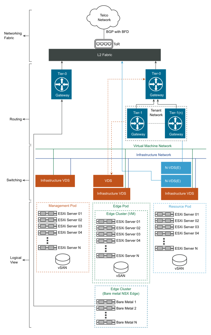
The following diagram depicts the physical representation of the compute and networking connectivity and the logical layers of the switching and routing fabric. This diagram illustrates the deployment of both the Edge form factors (VM and Bare Metal). Your deployment will include only one form factor.
The initial deployment of a Three-Pod design is more hardware intensive than the initial deployment of a Two-Pod design. Each Pod in the design scales up independently from the others. A Three-Pod design consists of the same components as in a Two-Pod design, as the way functions are combined to form the solution is different in each design. Regardless of the Pod design, VNFs perform the same way.
Logical View
-
Management Pod: Hosts all the management components. Its functions include resource orchestration, analytics, BCDR, third-party management, NFVO, and other ancillary management.
-
Edge Pod: Hosts the NSX-T Data Center network components, which are the NSX Edge nodes. Edge nodes participate in East-West traffic forwarding and provide connectivity to the physical infrastructure for North-South traffic management and capabilities. Edge nodes can be deployed in a VM and bare metal form-factor to meet capacity and performance needs.
-
Resource Pod: Provides the virtualized runtime environment (compute, network, and storage) to execute workloads.
Routing and Switching
Before deploying the Three-Pod configuration, consider a VLAN design to isolate the traffic for infrastructure, VMs, and VIM.
The vSphere Distributed Switch port groups have different requirements based on the Pod profile and networking requirements. For example, a vSphere Distributed Switch can be used for both the VMkernel traffic and VM management traffic. While the switching design is standardized for the Management and Edge Pods, the Resource Pod offers flexibility with two classes of NSX-T Data Center switches (N-VDS Standard and N-VDS Enhanced). The N-VDS switch offers the overlay and VLAN networking. The N-VDS Enhanced switch offers acceleration by using DPDK.
The two-tiered routing fabric of NSX-T Data Center provides the separation between the provider routers (Tier-0) and the tenant routers (Tier-1).
The Edge nodes provide the physical connectivity to the CSP's core and external networking.
NSX-T Data Center requires a minimum of 1600 MTU size for overlay traffic. The recommended MTU size is 9000.
