


By using NSX-T Data Center, virtualization delivers for networking what it has already delivered for compute and storage.
The server virtualization programmatically creates, takes snapshots of, deletes, and restores software-based VMs. Similarly, the NSX-based network virtualization programmatically creates, takes snapshots of, deletes, and restores software-based virtual networks. As a result, you follow a simplified operational model for the underlying physical network.
NSX-T Data Center is a non-disruptive solution. You can deploy it on any IP network such as traditional networking models and next-generation fabric architectures, regardless of the vendor. This is accomplished by decoupling the virtual networks from their physical counterparts.
NSX Manager
NSX Manager is the centralized network management component of NSX-T Data Center. It implements the management and control plane for the NSX infrastructure.
NSX Manager provides the following:
The Graphical User Interface (GUI) and the RESTful API for creating, configuring, and monitoring NSX-T components, such as segments and gateways.
An aggregated system view.
A method for monitoring and troubleshooting workloads attached to virtual networks.
Configuration and orchestration of the following services:
Logical networking components, such as logical switching and routing
Networking and edge services
Security services and distributed firewall
A RESTful API endpoint to automate consumption. Because of this architecture, you can automate all configuration and monitoring operations using any cloud management platform, security vendor platform, or automation framework.
Some of the components of the NSX Manager are as follows:
NSX Management Plane Agent (MPA): Available on each ESXi host. The MPA persists the desired state of the system and communicates Non-Flow-Controlling (NFC) messages such as configuration, statistics, status, and real-time data between transport nodes and the management plane.
NSX Controller: Controls the virtual networks and overlay transport tunnels. The controllers are responsible for the programmatic deployment of virtual networks across the entire NSX-T architecture.
Central Control Plane (CCP): Logically separated from all data plane traffic. A failure in the control plane does not affect existing data plane operations. The controller provides configuration to other NSX Controller components such as the segments, gateways, and edge VM configuration.
Virtual Distributed Switch
NSX in vSphere 7 and newer environments can use the vSphere Distributed Switch which makes the management of switches simpler. When an ESXi host is prepared for NSX-T, new vSphere Installable Bundles (VIBs) are installed on the host to enable this functionality. The vSphere Distributed Switch provides the underlying forwarding service that each segment relies on. To implement network virtualization, a network controller must configure the ESXi host virtual switch with network flow tables. The network flow tables form the logical broadcast domains the tenant administrators define when they create and configure segments.
NSX-T Data Center implements each logical broadcast domain by tunneling VM-to-VM traffic and VM-to-gateway traffic using the Geneve tunnel encapsulation mechanism. The network controller has a global view of the data center and ensures that the virtual switch flow tables in the ESXi host are updated as the VMs are created, moved, or removed.
NSX-T Data Center implements virtual switching in Standard and Enhanced modes. The enhanced data path provides superior network performance for telco workloads. ENS mode supports both overlay and VLAN traffic.
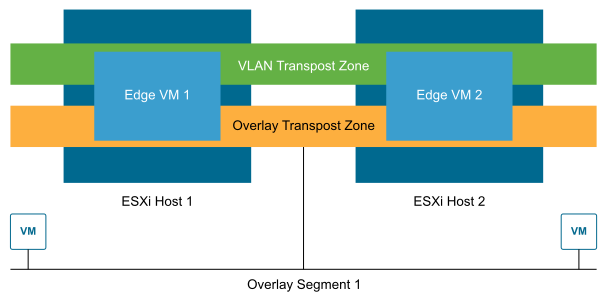
Transport Zones
Transport zones determine which hosts can use a particular network. A transport zone identifies the type of traffic, such as VLAN or overlay. You can configure one or more transport zones. A transport zone does not represent a security boundary.
Logical Switching
NSX Segments create logically abstracted segments to which the workloads can be connected. A single NSX Segment is mapped to a unique Geneve segment ID that is distributed across the ESXi hosts in a transport zone. NSX Segments support switching in the ESXi host without the constraints of VLAN sprawl or spanning tree issues.
Gateways
NSX Gateways provide the North-South connectivity for the workloads to access external networks and East-West connectivity between different logical networks.
A gateway is a configured partition of a traditional network hardware router. It replicates the functionality of the hardware, creating multiple routing domains in a single router. Gateways perform a subset of the tasks that are handled by the physical router. Each gateway can contain multiple routing instances and routing tables. Using gateways can be an effective way to maximize router use.
Distributed Router: A Distributed Router (DR) spans ESXi hosts whose VMs are connected to this gateway, and edge nodes the gateway is bound to. Functionally, the DR is responsible for one-hop distributed routing between segments and other gateways connected to this Gateway.
Service Router: A Service Router (SR) delivers services such as stateful Network Address Translation (NAT) that are not currently implemented in a distributed fashion. A Gateway always has a DR. A Gateway has SRs when it is a Tier-0 Gateway or a Tier-1 Gateway and has services configured such as load balancing, NAT, or Dynamic Host Configuration Protocol (DHCP).
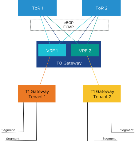
Virtual Routing and Forwarding
A Virtual Routing and Forwarding (VRF) gateway ensures that multiple instances of a routing table exist within the same gateway at the same time. VRFs are the Layer 3 equivalent of a VLAN. A VRF gateway must be linked to a Tier-0 gateway. From the Tier-0 gateway, the VRF gateway inherits the failover mode, Edge cluster, internal transit subnet, T0-T1 transit subnets, and BGP routing configuration.
In a multi-tenant solution, such as this architecture, VRFs allow a single Tier-0 gateway to be deployed and managed while isolating the routing tables between tenants. Each VRF can peer to a different eBGP neighbor and Autonomous System (AS).
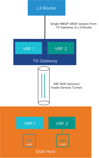
Ethernet VPN
Ethernet VPN (EVPN) is a standards-based BGP control plane that enables the extension of Layer 2 and Layer 3 connectivity.
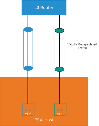
In the Route Server mode, EVPN allows a workload such as an Evolved Packet Core (EPC) that supports BGP peering and requires high throughput and low latency to bypass the NSX edge node and route traffic directly to the physical network.
The NSX edge lies only in the control plane and not the data plane. The NSX edge peers to both the workload and the physical network. The data path bypasses the NSX edge node and routes directly to the physical network using VXLAN encapsulation, enabling high throughput and low latency required by this class of applications.
Design Recommendation |
Design Justification |
Design Implication |
|---|---|---|
Deploy a three-node NSX Manager cluster using the large-sized appliance to configure and manage all NSX-based compute clusters. |
The large-sized appliance supports more than 64 ESXi hosts. The small-sized appliance is for proof of concept and the medium size supports up to 64 ESXi hosts only. |
The large-size deployment requires more resources in the management cluster. |
Create a VLAN and Overlay Transport zone. |
Ensures that all Segments are available to all ESXi hosts and edge VMs configured as Transport Nodes. |
None |
Configure ESXi hosts to use the vSphere Distributed Switch with enhanced data path mode in each compute cluster. |
Provides a high-performance network stack for NFV workloads. |
Enhanced data path mode requires more CPU resources compared to standard or ENS interrupt mode. |
Use large-sized NSX Edge VMs. |
The large-sized appliance provides the required performance characteristics, if a failure occurs. |
Large-sized Edges consume more CPU and memory resources. |
Deploy at least two large-sized NSX Edge VMs in the vSphere Edge Cluster. |
Creates the NSX Edge cluster to meet availability requirements. |
None |
Create an uplink profile with the load balance source teaming policy with two active uplinks for ESXi hosts. |
For increased resiliency and performance, supports the concurrent use of two physical NICs on the ESXi hosts by creating two TEPs. |
None |
Create a second uplink profile with the load balance source teaming policy with two active uplinks for Edge VMs. |
For increased resiliency and performance, supports the concurrent use of two virtual NICs on the Edge VMs by creating two TEPs. |
None |
Create a Transport Node Policy with the VLAN and Overlay Transport Zones, VDS settings, and Physical NICs per vSphere Cluster. |
Allows the profile to be assigned directly to the vSphere cluster and ensures consistent configuration across all ESXi hosts in the cluster. |
You must create all required Transport Zones before creating the Transport Node Policy. |
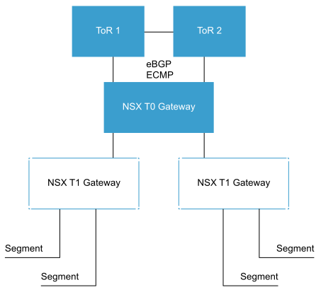
Create two VLANs to enable ECMP between the Tier-0 Gateway and the Layer 3 device (ToR or upstream device).
Note:
The ToR switches or the upstream Layer 3 devices have an SVI on one of the two VLANS. Each edge VM has an interface on each VLAN. |
Supports multiple equal-cost routes on the Tier-0 Gateway and provides more resiliency and better bandwidth use in the network. |
Extra VLANs are required. |
Deploy an Active-Active Tier-0 Gateway. |
Supports ECMP North-South routing on all edge VMs in the NSX Edge cluster. |
Active-Active Tier-0 Gateways cannot provide services such as NAT. If you deploy a specific solution that requires stateful services on the Tier-0 Gateway, you must deploy a Tier-0 Gateway in Active-Standby mode. |
Create two VLANs per VRF to enable ECMP between the Tenant VRFs and the Layer 3 device (ToR or upstream device).
Note:
The ToR switches or the upstream Layer 3 devices have an SVI on one of the two VLANS. Each edge VM has an interface on each VLAN. |
Supports multiple equal-cost routes on the VRFs and provides more resiliency and better bandwidth use in the network. |
Extra VLANs are required. |
Deploy a VRF per tenant. |
Allows each tenant to maintain their own isolated routing table. By using VRFs a single NSX Edge Cluster and T0 Gateway can be used for all tenants. |
Similar to T0 gateways, VRFs must be created manually before VMware Cloud Director can use them. |
Create Tier-1 Gateways for each tenant and connect them to the tenants VRF. |
Creates a two-tier routing architecture that supports load balancers and NAT. Because the Tier-1 is always Active/Standby, creation of services such as load balancers or NAT is possible. |
None |
Deploy Tier-1 Gateways with the Non-Preemptive setting. |
Ensures that when the failed Edge Transport Node comes back online it does not move services back to itself resulting in a small service outage. |
None |
Replace the certificate of the NSX Manager instances with a certificate that is signed by a third-party Public Key Infrastructure. |
Ensures that the communication between NSX administrators and the NSX Manager instance is encrypted by using a trusted certificate. |
Replacing and managing certificates is an operational overhead. |
Replace the NSX Manager cluster certificate with a certificate that is signed by a third-party Public Key Infrastructure. |
Ensures that the communication between the virtual IP address of the NSX Manager cluster and NSX administrators is encrypted by using a trusted certificate. |
Replacing and managing certificates is an operational overhead. |
This design describes VM-based NSX Edges. If required, Bare Metal Edges can be used instead of the VM-based NSX Edges.
