


You can implement the switch fabric at the physical layer by providing Layer 2 or Layer 3 transport services. For a scalable and vendor-neutral data solution, use a Layer 3 transport.
Both layer 2 and layer 3 transport have their sets of benefits and drawbacks. When deciding on an architecture, consider the following benefits and drawbacks of layer 2 and layer 3 transport.
Layer 2 Transport Considerations
The following considerations apply to a design that uses Layer 2 transport:
Top-of-Rack (ToR) switches and upstream Layer 3 devices such as core switches and routers form a switched fabric.
The upstream Layer 3 devices terminate each VLAN and provide the default gateway functionality.
Uplinks from the ToR switch to the upstream Layer 3 devices are 802.1Q trunks carrying all required VLANs.
Figure 1. Layer 2 Transport 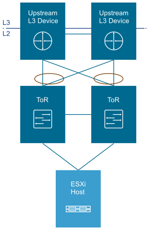
Characteristic |
Description |
|---|---|
Benefits |
|
Drawbacks |
|
Layer 3 Transport Considerations
The following considerations apply to a design that uses Layer 3 transport:
Layer 2 connectivity is limited to the ToR switches.
The ToR switch terminates each VLAN and provides the default gateway functionality. That is, it has a Switch Virtual Interface (SVI) for each VLAN.
Uplinks from the ToR switch to the upstream layer are routed point-to-point links. You cannot use VLAN trunking on the uplinks.
A dynamic routing protocol such as external Border Gateway Protocol (eBGP) connects the ToR switches and upstream switches. Each ToR switch advertises the prefixes, typically one per VLAN or subnet. In turn, the ToR switch calculates equal-cost paths to the prefixes received from the upstream layer it peers with.
Figure 2. Layer 3 Transport 
Characteristic |
Description |
|---|---|
Benefits |
|
Drawbacks |
|
Physical Network Interfaces
Telco Cloud Infrastructure requires that ESXi hosts contain four or more physical NICs of the same speed. Switch ports supporting the ESXi hosts must have the required VLANs tagged.
VMware vSphere Distributed Switch (vDS) supports several NIC teaming options. Load-based NIC teaming ensures the optimal use of available bandwidth and redundancy in case of a link failure. Use a minimum of four physical network interfaces for compute and two for management and edge clusters. Use physical network interfaces with 25 GbE or greater throughput in combination with a pair of ToR switches. Depending on the switch vendor, 802.1Q network trunks can support a maximum of 4095 or 4096 VLANs.
