


Two-tier, leaf-and-spine network architecture is the optimal approach for building the infrastructure for the Telco Cloud Infrastructure Cloud Director Edition platform. The two-tier architecture uses an access or a leaf switch that is connected to an aggregation or a spine switch. The leaf switch provides connectivity between endpoints in the data center, and the spine switch provides high-speed connectivity between the leaf switches. The leaf-and-spine network is connected in a full mesh, providing predictable communication and latency between endpoints. Ethernet connectivity is used from the host to the leaf switch, and the broadcast domain terminates at the leaf. External Border Gateway Protocol (eBGP) is the control plane option for routing within the leaf-and-spine architecture.

The Telco Cloud Infrastructure Cloud Director Edition platform consists of infrastructure networks and Virtual Machine networks. An infrastructure network is a host-level network that connects hypervisors to physical networks. Each ESXi host has multiple port groups configured for each infrastructure network.
The ESXi hosts in each pod are attached to vSphere Distributed Switches that provide a consistent network configuration across multiple hosts. One vSphere Distributed Switch handles the VM networks, and another switch handles the infrastructure networks. The N-VDS switch serves as the transport for the telco workload traffic.
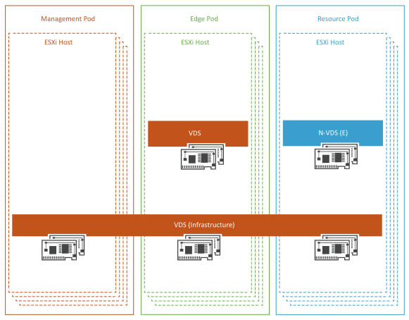
VMs can connect over a VLAN- or GENEVE-based overlay tunnel. Both types of networks are designed according to the requirements of the workloads hosted by a specific pod. The infrastructure vSphere Distributed Switch networks remain the same regardless of the pod function. However, the VM networks depend on the networks required by the specific pod. Management VMs use vSphere Distributed Switch. The VM networks created by NSX-T Data Center provide enhanced networking services and performance to the pod workloads. The ESXi host physical NICs are used as uplinks to connect the vSphere Distributed Switch and N-VDS switches to the physical network switches. All ESXi physical NICs connect to the Layer 2 or Layer 3 managed switches on the physical network. For Top-of-Rack (ToR) switches, at least two 10 GB Ethernet switches with enough ports are required to host all the physical NICs from each host.
Infrastructure Networks
Each ESXi host has multiple VMkernel port groups that are configured as infrastructure networks. The infrastructure networks include:
-
vMotion Network for the vSphere vMotion traffic.
-
vSAN Network for the vSAN shared storage traffic.
-
ESXi Management for the ESXi host management traffic.
-
vSphere Replication Network for communication between hosts at the protected and recovery sites.
Tenant Networks
-
Management vCenter Server: Tenant networks (VLAN-backed) interconnect the VMs of Telco Cloud Infrastructure components. These networks are configured on a dedicated tenant VDS in each of the pods.
-
Resource vCenter Server: VNF Network is used for VNF-to-VNF communication.
