Before deploying VMware Telco Cloud Operations, obtain the distribution OVAs.

Two different OVAs are required: control plane node and worker.
  • VMware-TCOps-Control-Plane-Node-<VERSION>-<BUILD_ID>.ova (for the control plane node VM)
  • VMware-TCOps-Worker-<VERSION>-<BUILD_ID>.ova (for the worker nodes VMs)

The following steps and screenshots are for vCenter 6.7, other versions of vCenter can differ and maintain general similarities.

VM Deployment

Procedure

  1. Deploy the control plane node VM.
    1. Log into the vCenter web user interface.
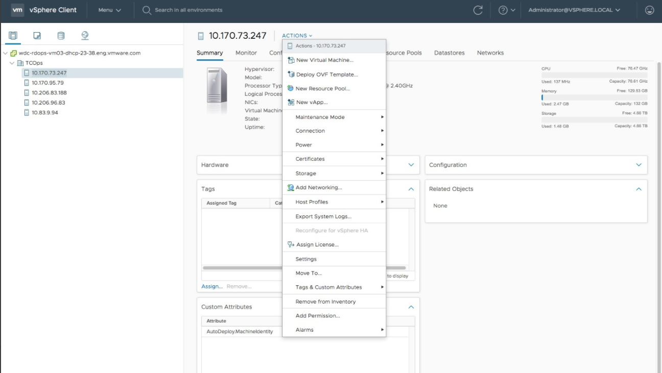
    2. Select the ESXi or cluster where the control plane node will deploy.
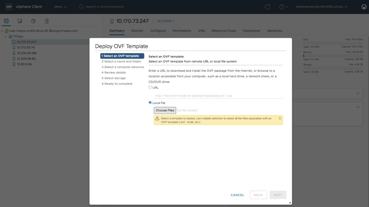
    3. From the ACTIONS menu, select Deploy OVF Template. The Deploy OVF Template wizard appears and leads you to the Select an OVF Template tab.
    4. Select URL and enter the URL from which the OVA can be downloaded, or select Local file and provide a path to the OVA and click NEXT.
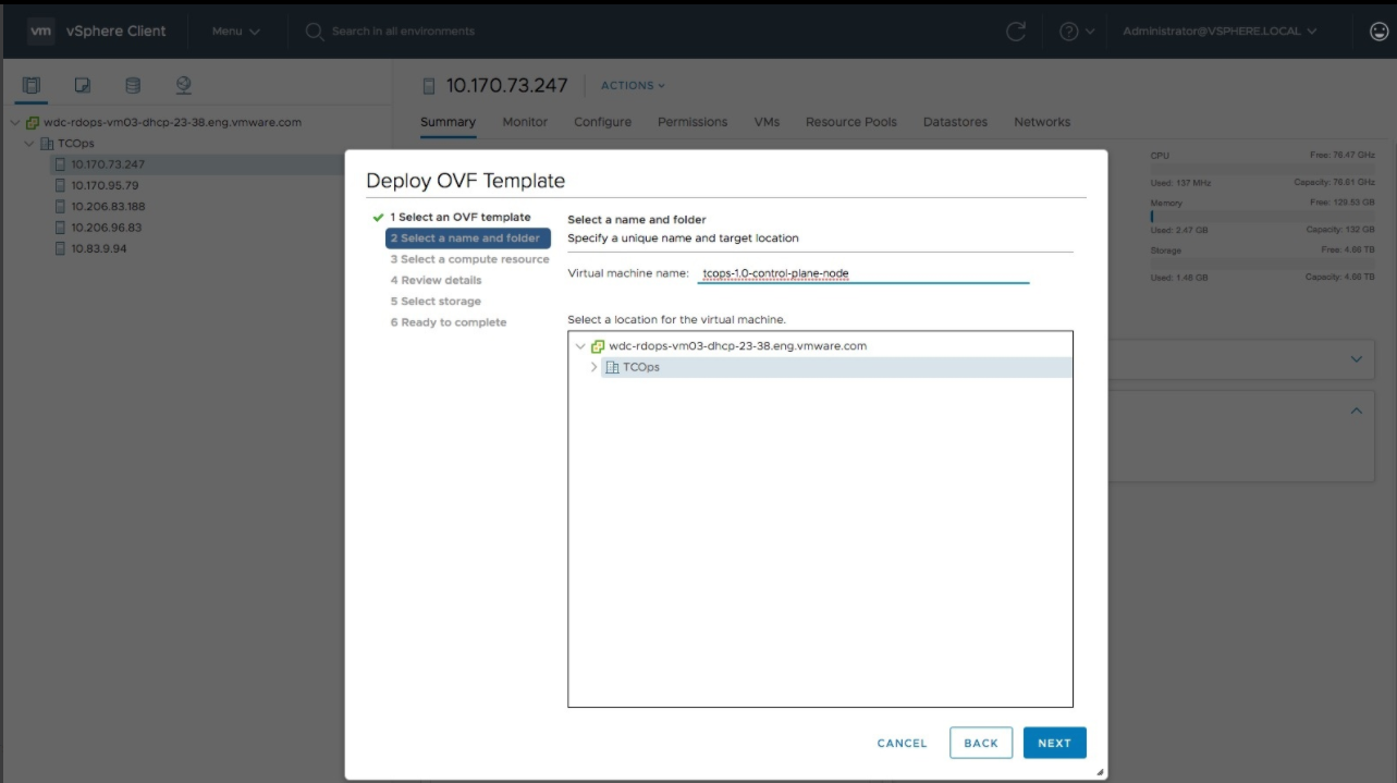
    5. Enter the desired name for the virtual machine and select a folder location as shown in the following screenshot and click Next.
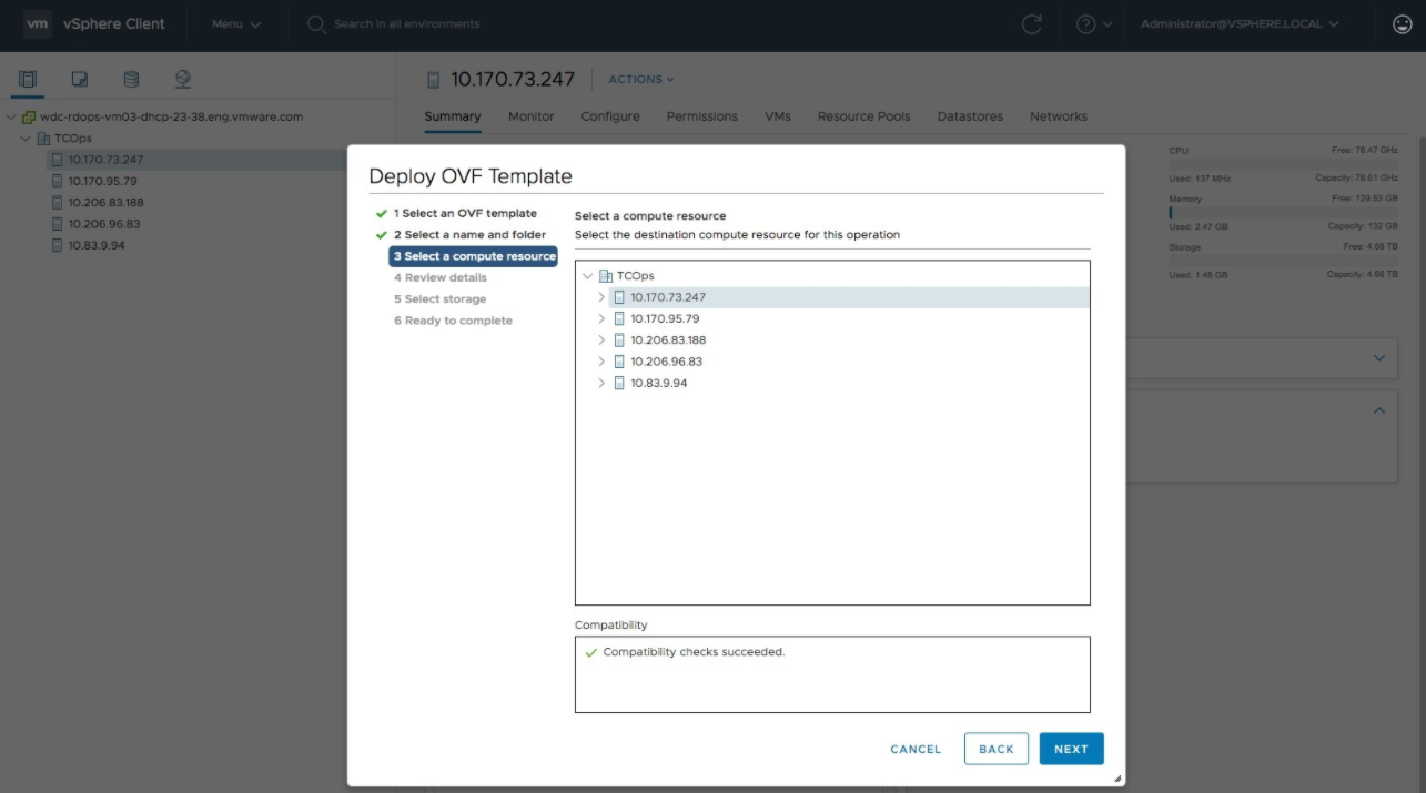
    6. Select the ESXi or cluster to which the control plane node OVA will be deployed and click NEXT.
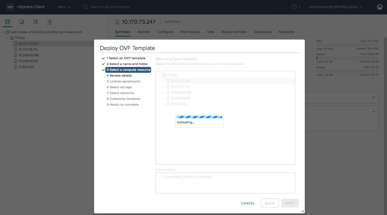
    7. Wait for validation.
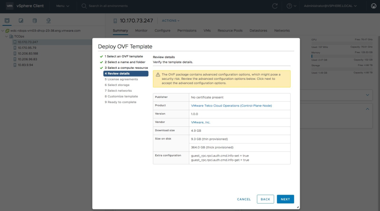
    8. Confirm that the information is correct in the Review details section, and click NEXT.
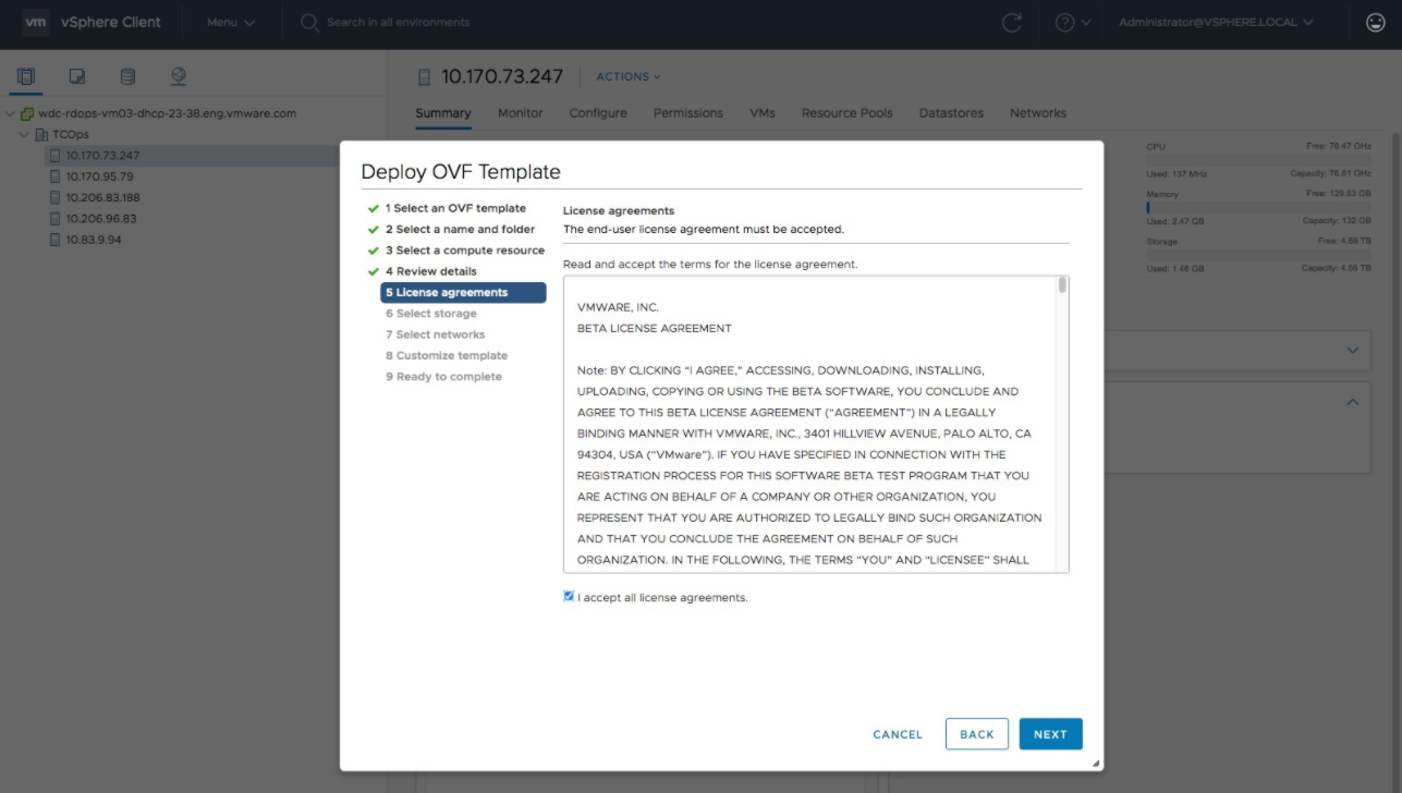
    9. Review the end-user license agreement, and select the box to accept. Click NEXT.
    10. Select the desired disk provisioning strategy and datastore for the control plane node OVA. Select NEXT.
      In vCenter, the default virtual disk format is set to Thick Provision Lazy Zeroed. See the following table for full provisioning descriptions. For further details, refer to VMware vCenter documentation.
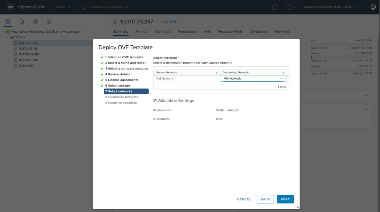
      Provisioning Description
      Thick Provision Lazy Zeroed This setting can be used if you have enough storage capacity to pre-allocate as per the footprint specifications for your VM before your begin deployment.
      Thick Provision This setting has a higher performance and pre-allocates and reserves the disk space.
      Thin Provision Claims disk space as needed, and uses less space in the beginning, but can reduce performance.
    11. Selected the desired network for the control plane node OVA, and click NEXT.
    12. Provide the desired configuration settings for the control plane node OVA in the Customize template tab.
      Note: The OVA does not require any settings for deployment. If settings are provided, the following describes how the settings are used.
      1. In the Administrator section, set the desired administrative user password (for username clusteradmin) and confirm.

        Optional: you can provide the public key string to SSH from the host with the public key. If no password is provided for the clusteradmin user, the default password VMware1! should be used to log in after the VM is deployed.

      2. In the Root User section:
        • Set the root password and confirm. If no password is provided for the root user, use the default password ChangeMe123!! to log in after the VM is deployed.
        • Set SSH Login to the desired root SSH log in policy (yes, no, or without password)
        • If selecting without password, set the public key string to SSH from the host with the public key.
      3. In the Management Network section, leave settings blank for DHCP, or enter the static IP (in CIDR format with "/") and default gateway IP.
      4. In the Container Networking section, leave the Docker Bridge setting as the default.
      5. In the DNS section, leave settings blank for DHCP, or enter the DNS server IP addresses and the default search domain.
      6. In the Network Time section, specify NTP hosts (optional).
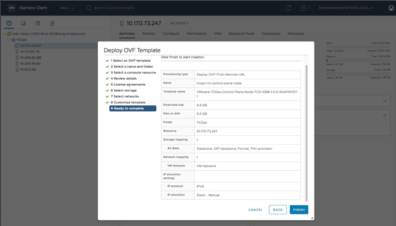
    13. Review the information in the Ready to complete tab, and click FINISH to proceed with the deployment.
  2. Wait for the control plane node to deploy.
  3. Customize the control plane node VM according to the deployment footprint you require. See Footprint Specifications, located in the VMware Telco Cloud Operations System Requirements section to find the requirements for each size of deployment: Extra Small (.5 5 K), Small (25 K), or Medium (50 K).
    Note: This step must be done before powering ON the VM.
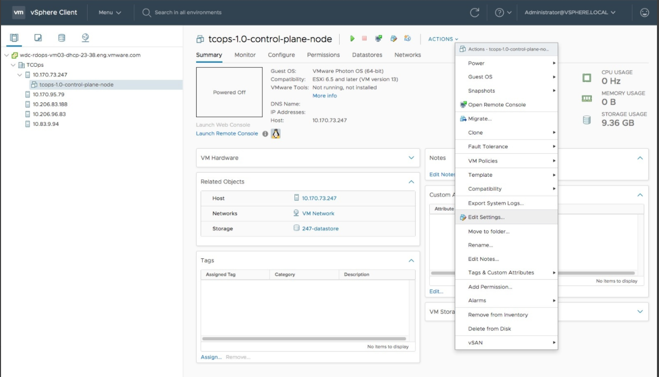
    1. Select the control plane node VM.
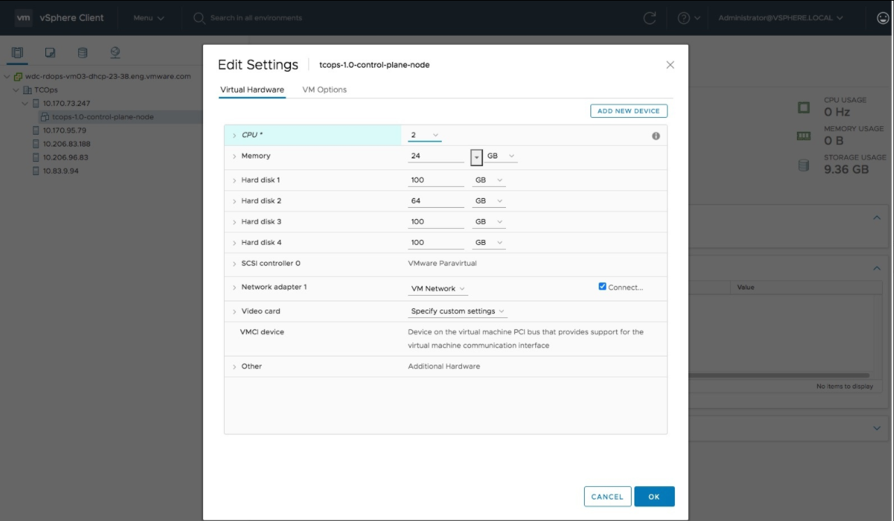
    2. From the ACTIONS menu, select Edit Settings.
    3. Finish the information in the Edit Settings form:
      • For the CPU setting, set the desired number of CPUs to allocate to the control plane node according to the deployment sizing guide. For example, 2 CPUs for a 25,000 device capacity server.
      • If necessary, for the Memory setting, set the desired amount of RAM to allocate to the control plane node according to the deployment sizing guide. For example, 8 GB for a 25,000 device-capacity server.
      • If necessary, for Hard disk 3 resize the data disk according to the Footprint Specification.
      • Click OK.

  4. Power on the control plane node. Wait for the control plane node to start. The node is assigned an IP address.
  5. Deploy four worker nodes (for each).
    1. Deploy the worker OVA. Follow the same steps (a through k) in step 1 for the control plane node VM.
    2. At the Customize template step of the Deploy OVF Template wizard, provide the desired configuration settings for the worker OVA.
      Note: All settings are optional. The OVA does not require any settings for deployment. If settings are provided, the following describes how the settings are used.
      Section Description
      Administrator Set the administrative user (clusteradmin) password and confirm. Optionally, you can provide the public key string to SSH from the host with the public key.
      Root User Set the root password and confirm.

      Set the SSH log in to the desired root SSH login policy (yes, no, or without password).

      If selecting without password, set the public key string to ssH from the host with the public key.

      Management Network Leave the settings blank for DHCP, or enter the static IP for the worker (must be in CIDR format with "/") and the default gateway IP.
      Container Networking Leave the Docker Bridge default setting.
      DNS Leave the settings blank for DHCP, or enter the DNS server IP addresses and the default search domain.
      Network Time Specify the NTP hosts (optional).
    3. Finish the Deploy OVF Template wizard by reviewing the details provided in the Ready to Complete step. Click FINISH.
    4. Wait for the worker to deploy. You should now have four worker VMs deployed.
    5. Customized each worker VM according to the deployment footprint you require. See Footprint Specifications, located in the VMware Telco Cloud Operations System Requirements section to find the requirements for each size of deployment: Extra Small (.5 5 K), Small (25 K), or Medium (50 K).
      Note: This step must be done before powering ON the VM.

      Verify one VM of each worker type (elasticworker, arangoworker, kafkaworker, and domainmanagers) is customized according to the footprint specification.

  6. Make note of the IP addresses of each of the five virtual machines. For example, one control pane node VM and the four worker node VMs. Also make note each node type you have customized. The information is required for the cluster deployment described in the following section.
    Cluster Deployment
  7. Visit the URL, https://<control plane node VM IP>:1081. You can safely accept any certificate errors that occur. When prompted, enter clusteradmin for the username and the password to the VM configured for the Administrative user. See the previous section, VM Deployment for more details.
  8. After logging in, click Server Deploy in the left navigation pane to view the Deployment UI.
  9. Navigate to the Load Configuation tab to populate the node configuration. Upload the deployed.vms file that contains the configuration or manually enter the details in the Global Configuration and Node Configuration sections.
    Note: If you deployed the VMs using the automated Deploy-Tool, deployed.vms file is generated and can be directly imported here. The generated file populates the details of the cluster in the Global and Node Configuration sections. For more details, see the Automated Deployment Process section in the VMware Telco Operations Deployment Guide.

    Because VM Deployment was done manually, you have to enter the following details. Click Next to expand the Global Configuration section.

  10. Enter the following details for a Global Configuration. The following details apply to all five nodes.
    Note: The settings you provide here replaces the values set during a VM deployment (phase 1). Configure the settings carefully.
    1. Select the footprint. Make sure you select the same footprint for which the VMs deployed have been configured for.
    2. (Required) Enter the password for the Admin account, for example, clusteradmin. The setting replaces what was entered during the VM deployment.
    3. (Optional) Provide the public key for the Admin account.
    4. (Required) Enter the Root Password. The setting replaces what was entered during the VM deployment.
    5. (Required) Select the root SSH access type. The setting replaces what was entered during the VM deployment.
    6. Keep the default values for Pod CIDR and Service CIDR.
    7. Click Next.
  11. Enter the following details for Node Configuration. Click Add Node and select the type of node. Enter the corresponding IP address from the deployed VMs. (Optional) You can clear the Use Global Settings box and enter separate details for the node. The system checks if the IP exists and belongs to the deployed VM. Click Deploy after all five nodes are added.
  12. Review the details on the Verify Configuration page. This page appears after the nodes are added. If the details are correct, click VERIFY FOOTPRINT. The system verifies that each VM is configured correctly to match the selected footprint specification.
    Note: If the verification fails, a message displays on the screen indicating which VMs were not configured and why. To fix the failed configuration, you must redeploy the VM, configure then settings, and power on the VM. Follow the steps to add the node again and verify the footprint.
  13. Cluster deployment begins. A Deployment Status page displays periodically for automatic updates. The Nodes: Ready: section appears when all five of the nodes created and Ready after all the service pods start and are fully deployed. When the deployment finishes, you can see a message indicating a successful installation.
  14. Click the Sam Config link in the left navigation pane after deployment. The link configures the authentication for the VMware Telco Cloud Operations system. Follow the procedure described in the VMware Telco Cloud Operations documentation.

What to do next