


The network virtualization design for RAN uses the vSphere Distributed Switch (VDS) along with VLAN requirements.
Network Segments and VLANs
Separate the different types of traffic for access security and to reduce the contention and latency.
According to the application or service, high latency on specific VM networks can also negatively affect performance. Determine which workloads and networks are sensitive to high latency by using the information gathered from the current state analysis and by interviewing key stakeholders and SMEs.
The following table lists the network segments and VLANs for a Cell Site host configuration.
VLAN |
Purpose |
|---|---|
ESXi Management |
vSphere management network |
Workload |
RAN workload network |
vSphere Distributed Switch (VDS) Design for RAN
VMware vSphere Distributed Switch (VDS) provides a centralized interface from which you can configure, monitor, and administer VM access switching for the entire Cell Site locations. The VDS extends the features and capabilities of virtual networks while simplifying provisioning and the ongoing configuration, monitoring, and management processes.
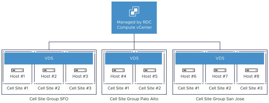
In the case of Cell Site ESXi hosts, create a single virtual switch per Cell Site group. The virtual switch can manage each type of network traffic, configure a port group to simplify the configuration and monitoring. Cell Site ESXi hosts are added to the data center object of vCenter server.
The VDS eases this management burden by treating the network as an aggregated resource. Individual host-level virtual switches are abstracted into one large VDS spanning multiple hosts. In this design, the data plane remains local to each VDS but the management plane is centralized.
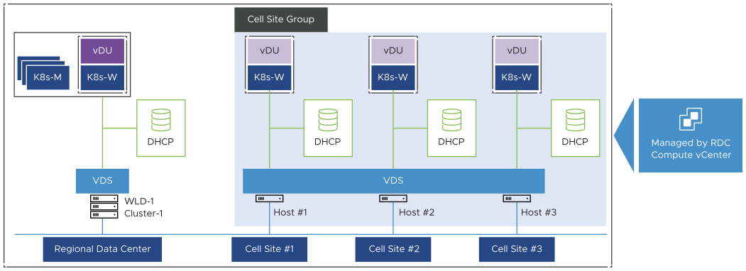
The following figure shows a dedicated VDS at Regional Data Center which is managing Kubernetes Cluster and Worker nodes along with vCU. Another VDS is configured to manage all Cell Site group hosts. Both VDS switches are managed by a Compute vCenter Server which is hosted at Regional Data Center.
Each vCenter Server instance can support up to 128 vSphere Distributed Switches. Each VDS can manage up to 2000 hosts. So, you must consider your Cell Site scaling appropriately.
Cell Site VDS
Use a vSphere Distributed Switch (VDS) for Cell Site hosts, based on the number of Cell Site Hosts, scaling options, and ease of network management in each cell site group. The network traffic between vCenter Server and an ESXi host should be 150ms or less.
VDS |
Limitation |
|---|---|
Shared VDS across Cell Sites in a cell site group. |
128 vSphere Distributed Switches supported per vCenter Server. |
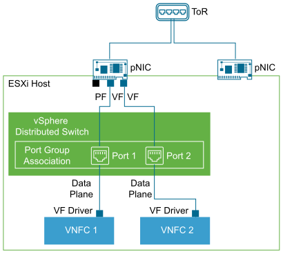
SR-IOV
SR-IOV is a specification that allows a single Peripheral Component Interconnect Express (PCIe) physical device under a single root port to appear as multiple separate physical devices to the hypervisor or the guest operating system.
SR-IOV uses Physical Functions (PFs) and Virtual Functions (VFs) to manage global functions for the SR-IOV devices. PFs are full PCIe functions that can configure and manage the SR-IOV functionality. VFs are lightweight PCIe functions that support data flow but have a restricted set of configuration resources. The number of VFs provided to the hypervisor or the guest operating system depends on the device. SR-IOV enabled PCIe devices require appropriate BIOS, hardware, and SR-IOV support in the guest operating system driver or hypervisor instance.
In vSphere, a VM can use an SR-IOV virtual function for networking. The VM and the physical adapter exchange data directly without using the VMkernel stack as an intermediary. Bypassing the VMkernel for networking reduces the latency and improves the CPU efficiency for high data transfer performance.
Recommended Network Virtualization Design
Design Recommendation |
Design Justification |
Design Implication |
|---|---|---|
Use two physical NICs in Cell Site ESXi host for workloads. |
Provides redundancy to all portgroups. |
None |
Use a minimum of one physical NIC (two recommended) in Cell Site ESXi host for PTP time synchronization. |
Provides time synchronization service |
None |
Use vSphere Distributed Switches. |
Simplifies the management of the virtual network. |
Migration from a standard switch to a distributed switch requires a minimum of two physical NICs to maintain redundancy. |
Use a single vSphere Distributed Switch per Cell Site Group |
Reduces the complexity of the network design. Provides more scalable architecture for Cell Site locations. |
Increases the number of vSphere Distributed Switches that must be managed. |
Use ephemeral port binding for the management port group. |
Provides the recovery option for the vCenter Server instance that manages the distributed switch. |
Port-level permissions and controls are lost across power cycles, and no historical context is saved. |
Use static port binding for all non-management port groups. |
Ensures that a VM connects to the same port on the vSphere Distributed Switch. This allows for historical data and port-level monitoring. |
None |
Enable health check on all vSphere distributed switches. |
Verifies that all VLANs are trunked to all ESXi hosts attached to the vSphere Distributed Switch and the MTU sizes match the physical network. |
You must have a minimum of two physical uplinks to use this feature. |
Use the Route based on the physical NIC load teaming algorithm for all port groups. |
|
None |
Enable Network I/O Control on all distributed switches. |
Increases the resiliency and performance of the network. |
If configured incorrectly, Network I/O Control might impact the network performance for critical traffic types. |
