


This section describes common external services such as DNS, DHCP, NTP, and PTP required for the Telco Cloud Platform RAN solution deployment.
Various external services are required for the deployment of the Telco Cloud Platform RAN components and Tanzu Kubernetes clusters. If you deploy the Telco Cloud Platform RAN solution in a greenfield environment, you must first deploy your Regional Data Center site and then onboard the Cell Sites to the Telco Cloud Platform RAN solution.
The following table lists the required external services and dependencies for the Regional Data Center sites and Cell Site locations:
Service |
Purpose |
|---|---|
Domain Name Services (DNS) |
Provides name resolution for various components of the Telco Cloud Platform RAN solution. |
Dynamic Host Configuration Protocol (DHCP) |
Provides automated IP address allocation for Tanzu Kubernetes clusters at Regional Data Center and Cell Site locations. Note: Ensure that the DHCP service is available local to each site. |
Network Time Protocol (NTP) |
Performs time synchronization between various Telco Core management components at Central Data Center or Regional Data Center. |
Precision Time Protocol (PTP) |
Distributes accurate time and frequency over telecom mobile networks and ESXi host at Cell Site locations. |
DNS
When you deploy the Telco Cloud Platform RAN solution, provide the DNS domain information for configuring various components of the solution. DNS resolution must be available for all the components in the solution, including servers, Virtual Machines (VMs), and virtual IPs. Before you deploy the Telco Cloud Platform RAN management components or create any workload domains, ensure that both forward and reverse DNS resolutions are functional for each component.
DHCP
Telco Cloud Platform RAN uses Dynamic Host Configuration Protocol (DHCP) to automatically configure Tanzu Kubernetes Cluster with an IPv4 address at Regional Data Center and the Cell Site location. Each RDC and Cell Site must have a dedicated DHCP service locally, and the DHCP scope must be defined and made available for this purpose. The defined scope must be able to accommodate all the initial and future Kubernetes workloads used in the Telco Cloud Platform RAN solution.
The following figure shows the deployment architecture of the DHCP service for a Regional Data Center and Cell Site location:
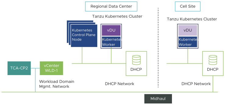
While deploying the Tanzu Kubernetes Control Plane, dedicate a static IP for the Kubernetes API endpoint.
NTP
All the management components of Telco Cloud Platform RAN must be synchronized against a common time by using the Network Time Protocol (NTP). The Telco Cloud Platform RAN components such as vCenter Server Single Sign-On (SSO) are sensitive to a time drift between distributed components. The synchronized time between various components also assists troubleshooting efforts.
The following guidelines apply to the NTP sources:
The IP addresses of NTP sources can be provided during the initial deployment of Telco Cloud platform RAN.
The NTP sources must be reachable by all the components in the Telco Cloud Platform RAN solution.
Time skew between NTP sources must be less than 5 minutes.
PTP
Precision Time Protocol (PTP) delivers time synchronization in various Telco applications and environments. It is defined in the IEEE 1588-2008 standard. PTP helps issuing accurate time and frequency over telecommunication mobile networks. Precise timekeeping is a key attribute for telco applications. It allows these applications to accurately construct the precise sequence of events that occurred or occur in real time. So, each ESXi node in the Telco Cloud Platform RAN solution must be time-synchronized.
The precision of a clock describes how consistent its time and frequency are relative to a reference time source, when measured repeatedly. The distinction between precision and accuracy is subtle but important.
PTP profiles: PTP allows various profiles to be defined to amend PTP for use in different scenarios. A profile is a set of specific PTP configuration options that are selected to meet the requirements of telco RAN applications.
PTP traffic: If the network carrying PTP comprises a non-PTP-aware switch in the pathway between the Grandmaster and Follower clocks, the switch handles PTP as any other data traffic, affecting the PTP accuracy. In this case, use a proper Quality-of-Service (QoS) configuration for network delivery to prioritize PTP traffic over all other traffic.
PTP grandmaster clocks: When networks are distributed geographically across different locations with Central Data Center, Regional Data Center, and Cell Site and they are connected over Wide Area Networks (WANs), varying latency across WAN links can compromise PTP accuracy. In that case, use different PTP Grandmaster clocks in each site and do not extend PTP across these sites.
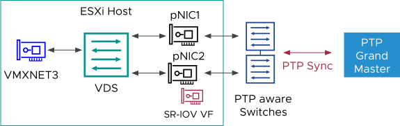
The following guidelines apply to the PTP sources: ESXi host must have a third physical NIC dedicated to PTP synchronization.
The PTP sources such as Telco Grandmaster Clock (T-GM) must be reachable by all the components in the Telco Cloud Platform RAN solution.
Use G.8275.1 PTP profile for accurate time synchronization for RAN applications. ITU–T G.8275.1 defines the PTP profile for network scenarios with full-timing support, which means all the intermediate switches support Boundary Clock functionality (BC).
To implement the ideal separation of Management and Workload switches for the Cell Site locations, each host must have a minimum of two dedicated physical NICs. The host can also have a single NIC with port separation and without redundancy. PTP can run on an SR-IOV VF or a dedicated physical port configured with PCI pass-through.
The following figure shows the PTP configuration on an ESXi host. In this scenario, the SR-IOV for PTP sync is configured on a VF associated with the pNIC2 port. The secondary NIC is required only when multiple NICs are used for redundancy and not related to PTP.
In the following diagram, a single socket server with a single worker node is used. For dual-socket servers, separate SR-IOV VFs or pass-through ports (one per NUMA) are required.
In case of a dual-socket host with NUMA placement, use physical NICs per NUMA socket to ensure NUMA alignment.
