


The physical network design for RAN includes defining the network topology for connecting physical switches and the ESXi hosts, determining switch port settings for VLANs, and designing routing.
Top-of-Rack Physical Switches
When configuring Top-of-Rack (ToR) switches, consider the following best practices:
-
Configure redundant physical switches to enhance availability.
-
Configure switch ports that connect to ESXi hosts manually as trunk ports. Virtual switches are passive devices and do not support trunking protocols, such as Dynamic Trunking Protocol (DTP).
-
Modify the Spanning Tree Protocol (STP) on any port that is connected to an ESXi NIC to reduce the time it takes to transition ports over to the forwarding state, for example, using the Trunk PortFast feature on a Cisco physical switch.
-
Configure jumbo frames on all switch ports, Inter-Switch Link (ISL), and Switched Virtual Interfaces (SVIs).
-
Configure PTP time synchronization on supported ToR switches.
Top-of-Rack Connectivity and Network Settings
Each ESXi host is connected redundantly to the network fabric ToR switches by using a minimum of two 10 GbE ports (25 GbE or faster ports are recommended). Configure the ToR switches to provide all necessary VLANs through an 802.1Q trunk. These redundant connections use the features of vSphere Distributed Switch to guarantee that the physical interface is not overrun and redundant paths are used if they are available.
-
Spanning Tree Protocol (STP): Although this design does not use the STP, switches usually include STP configured by default. Designate the ports connected to ESXi hosts as trunk PortFast.
-
Trunking: Configure the switch ports as members of an 802.1Q trunk.
-
MTU: Set MTU for all switch ports, VLANs, and SVIs to jumbo frames for consistency.
Jumbo Frames
IP storage throughput can benefit from the configuration of jumbo frames. Increasing the per-frame payload from 1500 bytes to the jumbo frame setting improves the efficiency of data transfer. Jumbo frames must be configured end-to-end. When you enable jumbo frames on an ESXi host, select an MTU size that matches the MTU size of the physical switch ports.
The workload determines whether to configure jumbo frames on a VM. Configure jumbo frames, if necessary, if the workload regularly transfers large volumes of network data. Also, ensure that both the VM operating system and the VM NICs support jumbo frames. Jumbo frames also improve the performance of vSphere vMotion.
Recommended Physical Network Design
| Design Decision |
Design Justification |
Design Implication |
|---|---|---|
| Use a layer 3 transport |
|
None |
| Implement the following physical network architecture:
|
|
Hardware choices might be limited. |
| Use two ToR switches for each Cell Site location for network high availability. |
|
Two ToR switches per Cell Tower can increase costs. |
| Use VLANs to segment physical network functions. |
|
Requires uniform configuration and presentation on all the switch ports made available to the ESXi hosts. |
| Assign static IP addresses to all management components. |
Ensures that interfaces such as management and storage always have the same IP address. This way, you provide support for continuous management of ESXi hosts using vCenter Server and for provisioning IP storage by storage administrators |
Requires precise IP address management. |
| Create DNS records for all ESXi hosts and management VMs to enable forward, reverse, short, and FQDN resolution. |
Ensures consistent resolution of management components using both IP address (reverse lookup) and name resolution. |
Adds administrative overhead. |
| Configure the MTU size to 9000 bytes (jumbo frames) on the physical switch ports, VLANs, SVIs, vSphere Distributed Switches, and VMkernel ports. |
Improves traffic throughput. |
When you adjust the MTU size, you must also configure the entire network path (VMkernel port, distributed switch, physical switches, and routers) to support the same MTU size. |
PTP Time Synchronization
RAN maintains network timing distribution as the preferred method for PTP time synchronization. For the RAN to operate effectively, the RU, DU, and CU must be time and phase synchronized. The delayed synchronization can have a negative impact on network applications. For example, low throughput, poor attachment success rate, and poor delivery success rate.
The accuracy of time synchronization is mostly dependent on the implementation of network connectivity and PTP protocol distribution. For example, the timestamp near interfaces and the number of hops. The O- RAN.WG4 Fronthaul networks define the following synchronization topologies for telco deployment:
-
LLS-C1 Configuration
-
LLS-C2 Configuration
-
LLS-C3 Configuration
-
LLS-C4 Configuration
Consider PTP time synchronization based on these designs. However, Telco Cloud Platform RAN supports LLS-C3 configuration only.
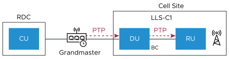
LLS-C1 Configuration
This configuration is done based on the point-to-point connection between DU and RU by using the network timing option. LLS-C1 is simple to configure. In this configuration, DU operates as PTP Boundary Clock (BC). The DU derives the time signal from Grandmaster and communicates directly with RU to synchronize it.
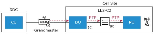
LLS-C2 Configuration
In this configuration, DU acts as PTP BC to allocate network timing towards the RU. One or more PTP-supported switches can be installed between the DU and RU.
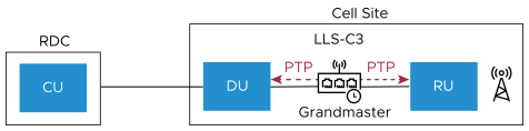
LLS-C3 Configuration
In this configuration, the PTP Grandmaster performs network time-sharing between DU and RU at Cell Sites. One or more PTP switches are allowed in the Fronthaul network to support network time-sharing. This architecture is widely adopted by introducing the PTP Grandmaster and PTP Switch, which provide the ideal solution for network time-sharing.
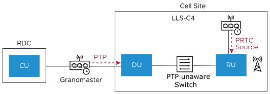
LLS-C4 Configuration
In this configuration, PRTC (usually the GNSS receiver) is used locally to provide timing for RU. PRTC does not depend on the Fronthaul transport network for timing and synchronization.
RAN Split and Fronthaul Network
3GPP defined eight functional split options for Fronthaul networks. Options 2 and 7.x are the most commonly adopted Radio Splits.
-
Option 2: A high-level CU and DU split. With the Option 2 split, the CU handles Service Data Adaptation Protocol (SDAP) or Packet Data Convergence Protocol (PDCP) with Radio Resource Control (RRC) while L2/L1 Ethernet functions reside in the DU. Before the data is sent across the Medium haul network, aggregation and statistical multiplexing of the data are done in the DU. So, the amount of data transmitted across the interface for each radio antenna appliance is reduced. PTP time synchronization is not mandatory for Option-2 split.
-
Option 7.x: A low-level DU and RU split. With Option 7 split, the DU handles the RRC/ PDCP/ Radio Link Control (RLC)/MAC and higher Physical (PHY) functions. The RU handles the lower PHY and RF functions. Mostly, a single DU is co-located with multiple RUs, offloading resource-intensive processing from multiple RUs. CU can be centrally located across the WAN, aggregating multiple DUs. Option 7.x lets operators simplify the deployment of the DU and RU, leading to a cost-effective solution and an ideal option for a distributed RAN deployment. Use LLC-C3 for PTP synchronization between the RU and DU.
Mobile operators require the flexibility to choose different splits based on the server hardware and fronthaul availability. Higher-layer functional splits are required for dense urban areas and scenarios, while a low fronthaul bit rate is required for a fronthaul interface. With Option 7.x, more functions are shifted to DUs, enabling more virtualization gains. Hence, Option 7.x split is more cost-effective than Option-2 DU split.
