


NSX is an implementation of software-defined networking. It provides network services such as switching, routing, load balancing, firewall, and Virtual Private Networking (VPN).
NSX focuses on providing networking, security, automation, and operational simplicity for the underlying physical network. NSX is a non-disruptive solution and can be deployed on any IP network such as traditional networking models and next-generation fabric architectures, regardless of the vendor. This is accomplished by decoupling the virtual networks from their physical counterparts.
NSX is applicable only when using Telco Cloud Platform Advanced.
NSX Manager
The NSX Manager is the centralized network management component of VMware NSX. It implements the management and control planes for the NSX infrastructure.
NSX Manager provides the following functions:
The Graphical User Interface (GUI) and the RESTful API for creating, configuring, and monitoring NSX components, such as segments and gateways.
An aggregated system view
A method for monitoring and troubleshooting workloads attached to virtual networks
Configuration and orchestration of the following services:
Logical networking components, such as logical switching and routing
Networking and edge services
Security services and distributed firewall
A RESTful API endpoint to automate consumption. Because of this architecture, you can automate all configuration and monitoring operations using any cloud management platform, security vendor platform, or automation framework.
Some of the components of the NSX Manager are as follows:
NSX Management Plane Agent (MPA): Available on each ESXi host. The MPA persists the desired state of the system and communicates Non-Flow-Controlling (NFC) messages such as configuration, statistics, status, and real-time data between transport nodes and the management plane.
NSX Controller: Controls the virtual networks and overlay transport tunnels. The controllers are responsible for the programmatic deployment of virtual networks across the entire NSX architecture.
Central Control Plane (CCP): Logically separated from all data plane traffic. A failure in the control plane does not affect existing data plane operations. The controller provides configuration to other NSX Controller components such as the segments, gateways, and edge VM configuration.
Local Control Plane (LCP): The LCP runs on transport nodes. It is adjacent to the dataplane it controls and is connected to the CCP. The LCP is responsible for programming the forwarding entries and firewall rules of the data plane.
Virtual Distributed Switch
vSphere Distributed switch (vSphere 7 and later versions) supports NSX Distributed Port Groups. NSX and vSphere integration consolidates the use of NSX on VDS, and this model is known as a Converged Virtual Distributed Switch (C-VDS).
NSX implements each logical broadcast domain by tunneling VM-to-VM traffic and VM-to-gateway traffic using the Geneve tunnel encapsulation mechanism. The network controller has a global view of the data center and ensures that the virtual switch flow tables in the ESXi host are updated as the VMs are created, moved, or removed.
NSX implements virtual switching in Standard and Enhanced Data Path (EDP) modes. EDP provides better network performance for telco workloads. The EDP mode supports both overlay and VLAN based network segments.
Transport Zones
Transport zones determine which hosts can consume a particular network. A transport zone identifies the type of traffic, such as VLAN, overlay, and the teaming Policy. You can configure one or more transport zones. A transport zone does not represent a security boundary.
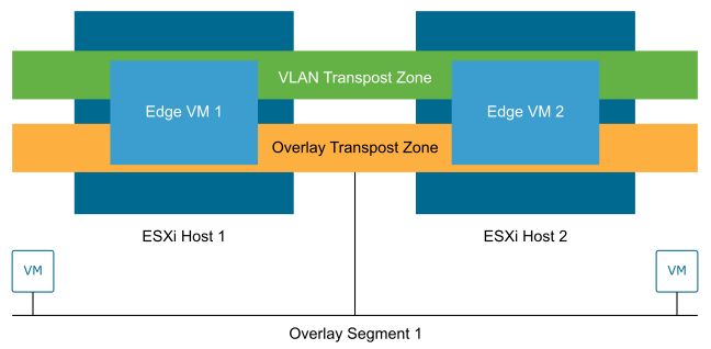
In NSX, when an ESXi host is converted into a transport node, it is attached to one or more transport zones. The switch type and mode are configured during the host provisioning or within the transport node profiles.
Only a single overlay transport zone is supported for ESXi hosts. Multiple VLAN transport zones can be configured.
Logical Switching
NSX Segments create logically abstracted segments to which the workloads can be connected. A single segment is mapped to a unique Geneve segment ID (or VLAN ID) that is distributed across the ESXi hosts (and NSX edge nodes) within a given transport zone. NSX Segments support switching in the ESXi host without the constraints of VLAN sprawl or spanning tree issues.
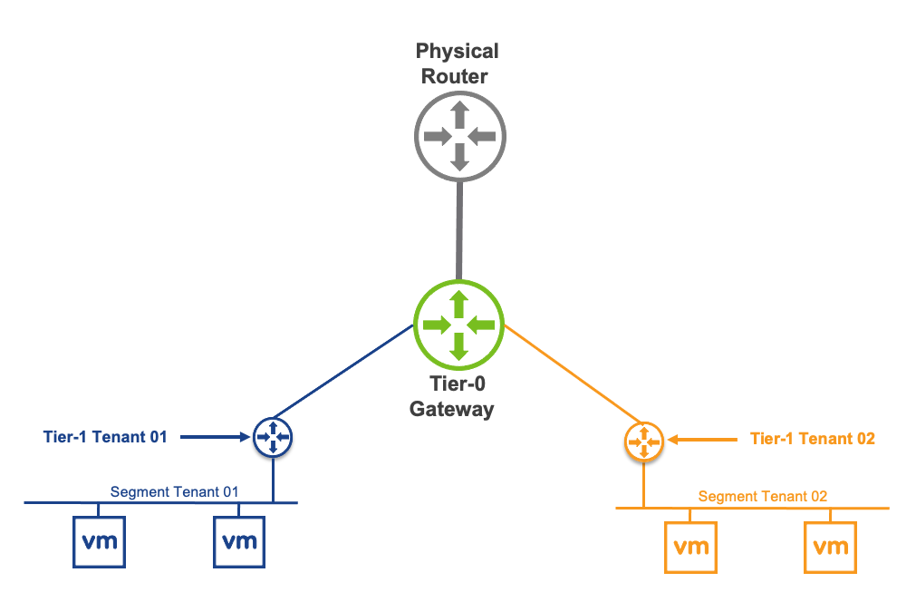
Gateways
NSX Gateways provide the North-South connectivity for the workloads to access external networks and the East-West connectivity between different logical networks.
A gateway is a configured partition of a traditional network hardware router. It replicates the functionality of the hardware, creating multiple routing domains in a single router. Gateways perform a subset of the tasks that are handled by the physical router. Each gateway can contain multiple routing instances and routing tables. Using gateways can be an effective way to maximize the use of routers.
Distributed Router: A Distributed Router (DR) spans across all ESXi nodes to which VMs are connected to the NSX gateway. The DR construct also expands to the edge nodes. Functionally, the DR is responsible for one-hop distributed routing between segments and other gateways connected to the NSX gateway.
Service Router: A Service Router (SR) implements stateful services such as Border Gateway Protocol (BGP) and stateful Network Address Translation (NAT). These services cannot be implemented in a distributed way. A gateway always has a DR. A gateway has SRs when it is a Tier-0 Gateway or a Tier-1 Gateway. It is configured with services such as load balancing, NAT, or Dynamic Host Configuration Protocol (DHCP).
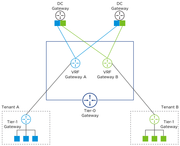
Virtual Routing and Forwarding
A Virtual Routing and Forwarding (VRF) gateway enables multiple instances of a routing table to exist simultaneously within the same gateway. A VRF is a layer 3 equivalent of a VLAN. A Tier-1 router or network segment must be linked to a tier-0 VRF gateway. The configuration of tier-0 VRF gateway is inherited from the parent T0 configuration.
In a multi-tenant solution, VRFs allow a single Tier-0 gateway to be deployed and managed while keeping the routing tables between tenants isolated. Each VRF can peer to a different eBGP neighbor and autonomous system (AS).
Enhanced Data Path
NSX Enhanced Data Path (EDP) is a networking stack mode, which provides better network performance. It is primarily designed for data plane intensive workloads.
When EDP mode is enabled on a transport node, a combination of technologies is used. The technologies include mbuf packet representation, DPDK fastpath, polling, flow-cache, dedicated CPUs, and vmxnet3 optimizations. These technologies together significantly accelerate the network traffic for the network function workloads.
The NSX EDP mode virtual switches use the same emulated virtual NIC adapter, VMXNET3, as the Standard or Distributed vSphere Virtual Switch. Unlike other solutions such as SR-IOV, you can consume EDP with no loss of functionality such as vMotion.
The NSX implementation of EDP remains in the ESXi Hypervisor space (vmkernel). Hence the user-space security concerns associated with open-source DPDK networking stacks are not applicable to EDP.
When using EDP, CPU cores must be pre-allocated to the infrastructure dimensioning plan. The CPU cores are assigned per EDP switch instance, per host, and per NUMA. The quantity depends on the throughput required by the workloads. SR-IOV, in comparison, does not require any CPU cores in the infrastructure compute budget. However, the benefits of EDP outweigh the CPU cores saved using SR-IOV.
The following table provides a high-level comparison between the two design choices:
NSX EDP only: A single virtual switch is used to manage data plane and non-data plane traffic.
NSX & SR-IOV: NSX Standard mode switch is used for non-data plane traffic. SR-IOV is used for data plane traffic.
Uplinks that are used for EDP switching cannot also be leveraged for SR-IOV VFs.
NSX EDP only |
NSX + SRIOV |
|
|---|---|---|
CPU |
2-4 physical cores per CPU Additional Core could be considered |
None Note: The assumption is that the NSX threads use the cores reserved for ESXi. |
NIC |
2 ports per socket |
2 ports for NSX 2 ports per socket for SR-IOV |
Throughput |
The lowest throughput among the physical network, EDP virtual switch, or workload. |
The lowest throughput among the physical network or the workload. |
Programmable L2/L3 networks (SDN) |
Fully programmable |
Not supported |
Programmable Edge |
Fully programmable, high-performance Edges |
Not supported |
End-to-end visibility and analytics |
Available |
Not supported |
Provisioning and resiliency |
NIC teaming, vMotion, HA, DRS |
Not supported |
Driver Standardization |
Available (VMXNET3) |
Not supported Note: Application vendor-specific drivers are required. |
NIC support |
VMware Hardware Compatibility List |
VMware + App Vendor HCL for SR-IOV |
Upgrade compatibility |
Available across NSX releases |
Vendor-specific for SR-IOV |
Support model |
VMware Carrier-Grade Support |
Complex multivendor resolution |
EDP is supported in conjunction with the Virtual Hyperthreading (vHT) functionality provided by vSphere 8. When configuring EDP interfaces as part of Dynamic Infrastructure Provisioning (DIP) in VMware Telco Cloud Automation. These interfaces can be consumed while configuring vHT.
The provisioning of EDP requires the assignment of lCores. These lCores must be considered for the overall resource budget.
To obtain optimal performance when using NSX EDP, consider adjusting options such as multiple contexts per device (ctxperdev) and RSS configurations to enhance throughput. Contact VMware support to determine the best configuration based on the application.
Ethernet VPN (EVPN)
Ethernet VPN (EVPN) is a standards-based BGP control plane that enables the extension of Layer 2 and Layer 3 connectivity.
In the Route Server mode, EVPN allows workloads such as an Evolved Packet Core (EPC) that supports BGP peering and high throughput and low latency to bypass the NSX edge node and route traffic directly to the physical network.
The NSX edge resides in the control path and not the data path. The NSX edge peers to both the workload and the physical network. The data path bypasses the NSX edge node and routes directly to the physical network using VXLAN encapsulation, enabling high throughput and low latency required by this class of applications.
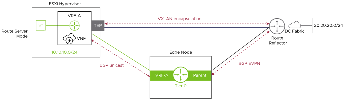
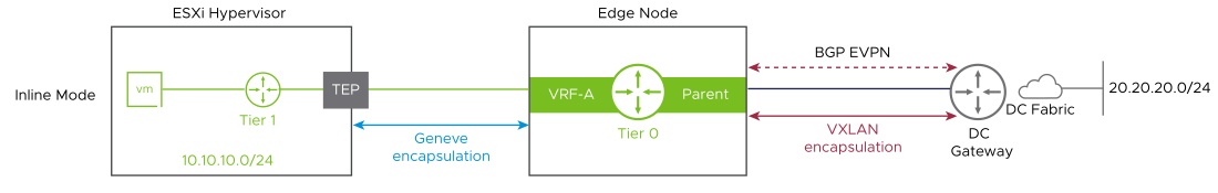
EVPN route server mode is implemented using a specific set of RFCs. These RFCs must be supported on the network underlay devices for the service to work end-to-end.
Design Recommendation |
Design Justification |
Design Implication |
Domain Applicability |
|---|---|---|---|
Deploy a three-node NSX Manager cluster using the large-sized appliance to configure and manage all NSX-based compute clusters. |
The large-sized appliance supports more than 64 ESXi hosts. The small-sized appliance is for proof of concept and the medium size supports up to 64 ESXi hosts only. |
The large-sized deployment requires more resources in the vSphere management cluster. |
Management domain, Compute clusters VNF, CNF, C-RAN, Near/Far Edge, and NSX Edge Not applicable to RAN sites |
Apply vSphere Distributed Resource Scheduler (DRS) anti-affinity rules to the NSX Manager/Controller cluster nodes. |
Using DRS prevents Manager or Controller nodes from running on the same ESXi host, and thereby risking their high availability. |
Additional configuration is required to set up anti-affinity rules and the rules must be maintained in the event of node restores. |
|
Create a VLAN and Overlay Transport zone. |
Ensures that all segments are available to all ESXi hosts and edge VMs are configured as Transport Nodes. |
None |
Management domain, Compute clusters VNF, CNF, C-RAN, Near/Far Edge, and NSX Edge Not applicable to RAN sites |
Configure ESXi hosts to use the vSphere Distributed Switch with EDP mode in each NSX compute cluster. |
Provides a high-performance network stack for NFV workloads. |
EDP mode requires more CPU resources, and compatible NICs compared to standard or ENS interrupt mode. |
|
Use large-sized NSX Edge VMs. |
The large-sized appliance provides the required performance characteristics if a failure occurs. |
Large-sized Edges consume more CPU and memory resources. |
|
Deploy at least two large-sized NSX Edge VMs in the vSphere Edge Cluster. |
Creates the NSX Edge cluster to meet availability requirements. |
None |
|
Create an uplink profile with the load balance source teaming policy with two active uplinks for ESXi hosts. |
For increased resiliency and performance, supports the concurrent use of two physical NICs on the ESXi hosts is supported by creating two TEPs. |
None |
|
Create a second uplink profile with the load balance source teaming policy with two active uplinks for Edge VMs. |
For increased resiliency and performance, supports the concurrent use of two virtual NICs on the Edge VMs by creating two TEPs. |
None |
|
Create a Transport Node Policy with the VLAN and Overlay Transport Zones, VDS settings, and Physical NICs per vSphere Cluster. |
Allows the profile to be assigned directly to the vSphere cluster and ensures consistent configuration across all ESXi hosts in the cluster. |
You must create all required Transport Zones before creating the Transport Node Policy. |
|
Create two VLANs to enable ECMP between the Tier-0 Gateway and the Layer 3 device (ToR or upstream device). The ToR switches or the upstream Layer 3 devices have an SVI on one of the two VLANs. Each edge VM has an interface on each VLAN. |
Supports multiple equal-cost routes on the Tier-0 Gateway and provides more resiliency and better bandwidth use in the network. |
Extra VLANs are required. |
|
Deploy an Active-Active Tier-0 Gateway. |
Supports ECMP North-South routing on all edge VMs in the NSX Edge cluster. |
Active-Active Tier-0 Gateways cannot provide services such as NAT. If you deploy a specific solution that requires stateful services on the Tier-0 Gateway, you must deploy a Tier-0 Gateway in Active-Standby mode. |
|
Deploy a Tier-1 Gateway to the NSX Edge cluster and connect it to the Tier-0 Gateway. |
Creates a two-tier routing architecture that supports load balancers and NAT. Because Tier-1 is always Active/Standby, the creation of services such as load balancers or NAT is possible. |
None |
|
Deploy Tier-1 Gateways with Non-Preemptive setting. |
Ensures that when the failed Edge Transport Node comes back online it does not move services back to itself resulting in a small service outage. |
None |
|
Replace the certificate of the NSX Manager instances with a certificate that is signed by a third-party Public Key Infrastructure. |
Ensures that the communication between NSX administrators and the NSX Manager instance is encrypted by using a trusted certificate. |
Replacing and managing certificates is an operational overhead. |
|
Replace the NSX Manager cluster certificate with a certificate that is signed by a third-party Public Key Infrastructure. |
Ensures that the communication between the virtual IP address of the NSX Manager cluster and NSX administrators is encrypted using a trusted certificate. |
Replacing and managing certificates is an operational overhead. |
