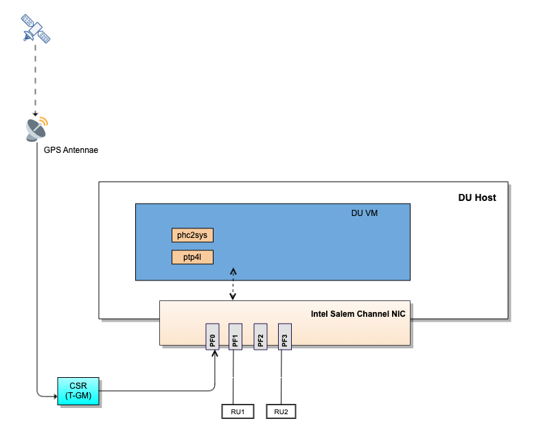
In LLS-C1 configuration, the DU operates PTP in T-BC mode, sourcing the network time from a Precision Real-Time-Clock/Telecom Grandmaster (PRTC/T-GM) in Midhual. When PTP runs in T-BC mode, one port functions as a Client to a remote PRTC/T-GM and other ports function as Servers, providing time to downstream devices.
In the following example topology, PF0 on the DU receives time from the Cell Site Router (CSR) functioning as T-GM and distributes time to the RUs connected on PF1 and PF3.
Procedure
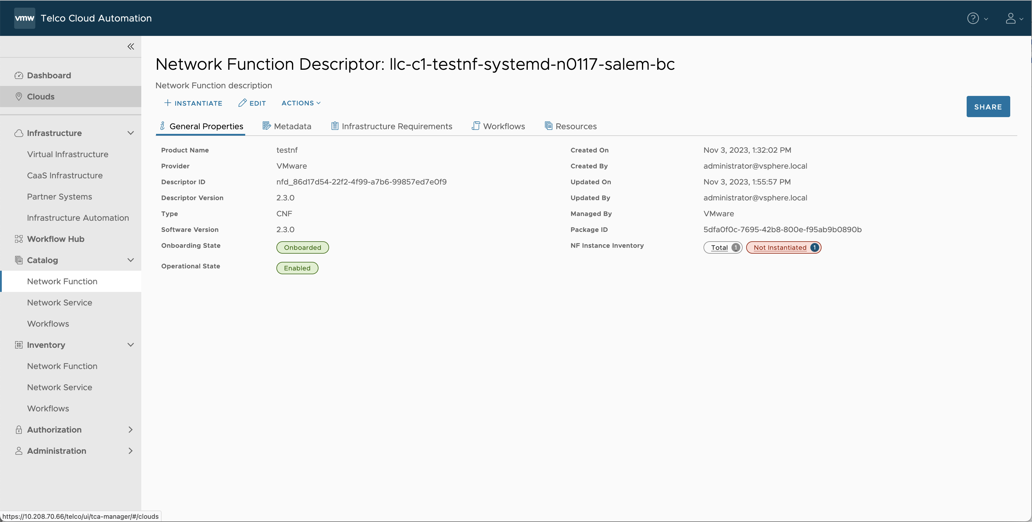
- Navigate to Catalog > Network Function in the Telco Cloud Automation UI.
- Select the Network Function you want to set up in T-BC mode and click EDIT.
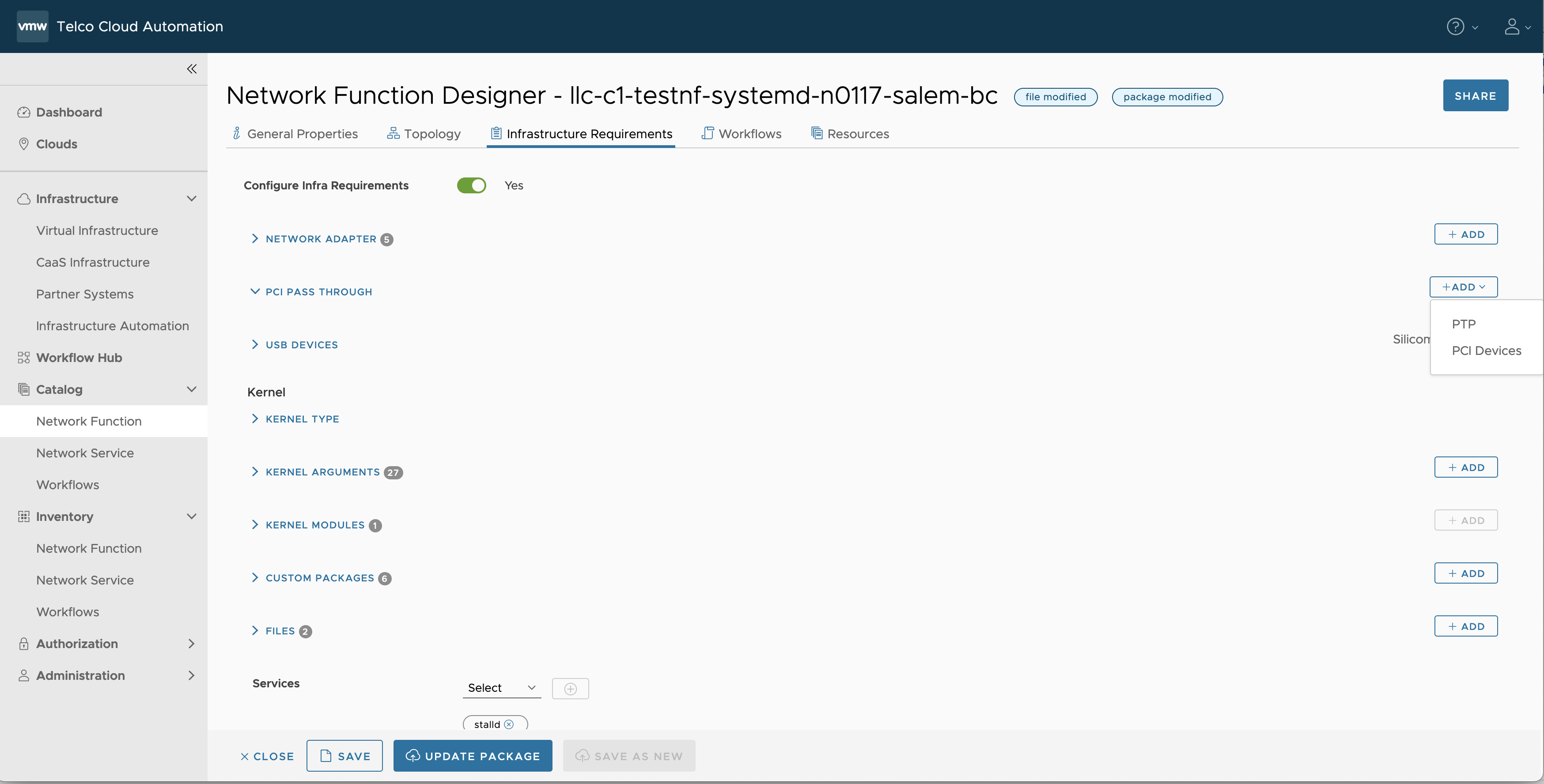
- Click the Infrastructure Requirements tab.
- Add PTP devices under PCI PASS THROUGH:
- Click ADD and select PTP from the drop-down list.
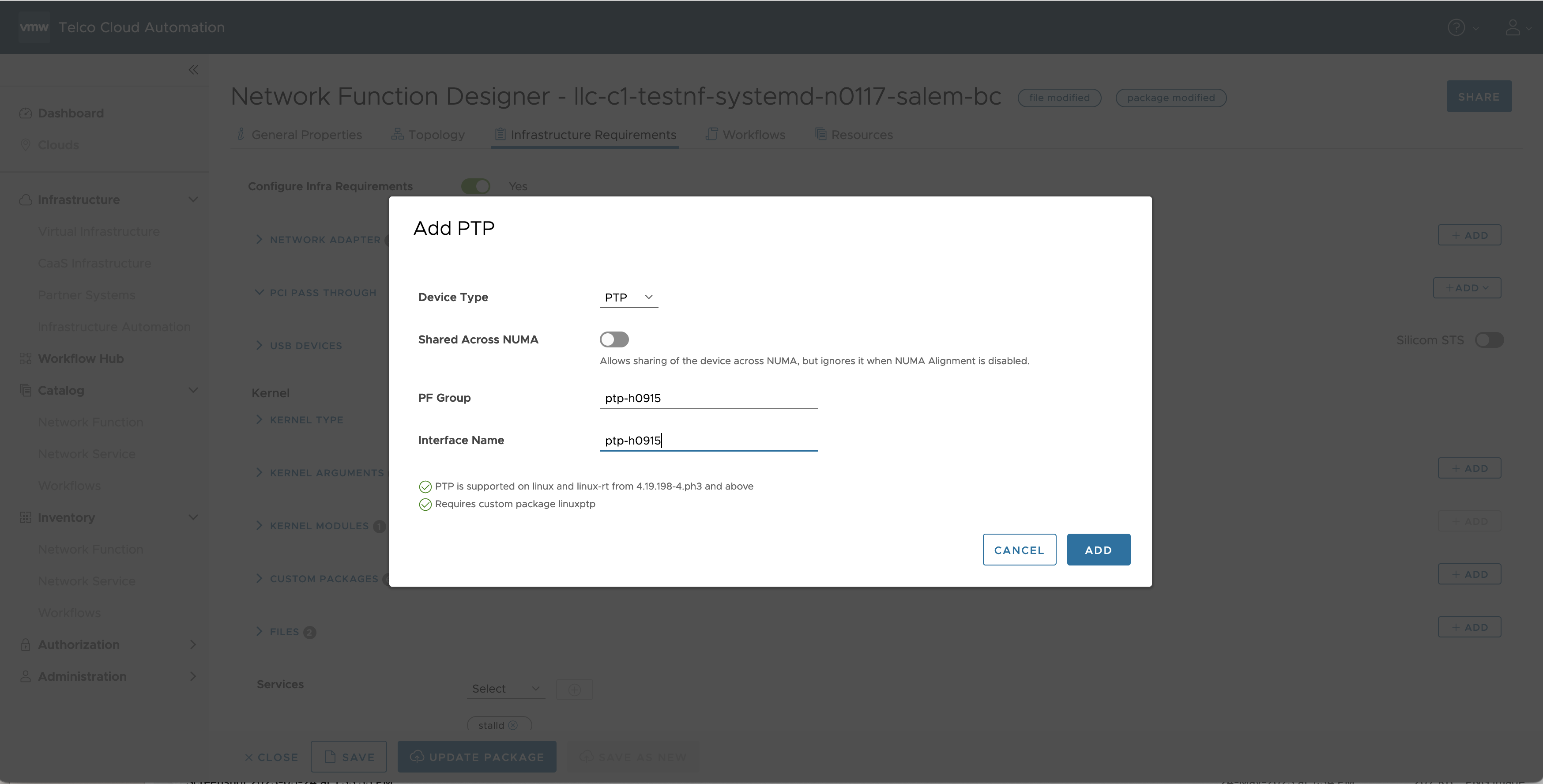
- In the Add PTP pop-up window, select PTP as the Device Type.
- Enable or disable Shared Across NUMA as required.
- Enter the name of the PF Group, the PCI Group that you created in the Host Profile. Example: ptp-h0915
- Enter the Interface Name you want to create for this PTP Device on the worker node. Example: ptp-h0915
- Click ADD.
- Repeat steps a-f for each PTP device you want to add.
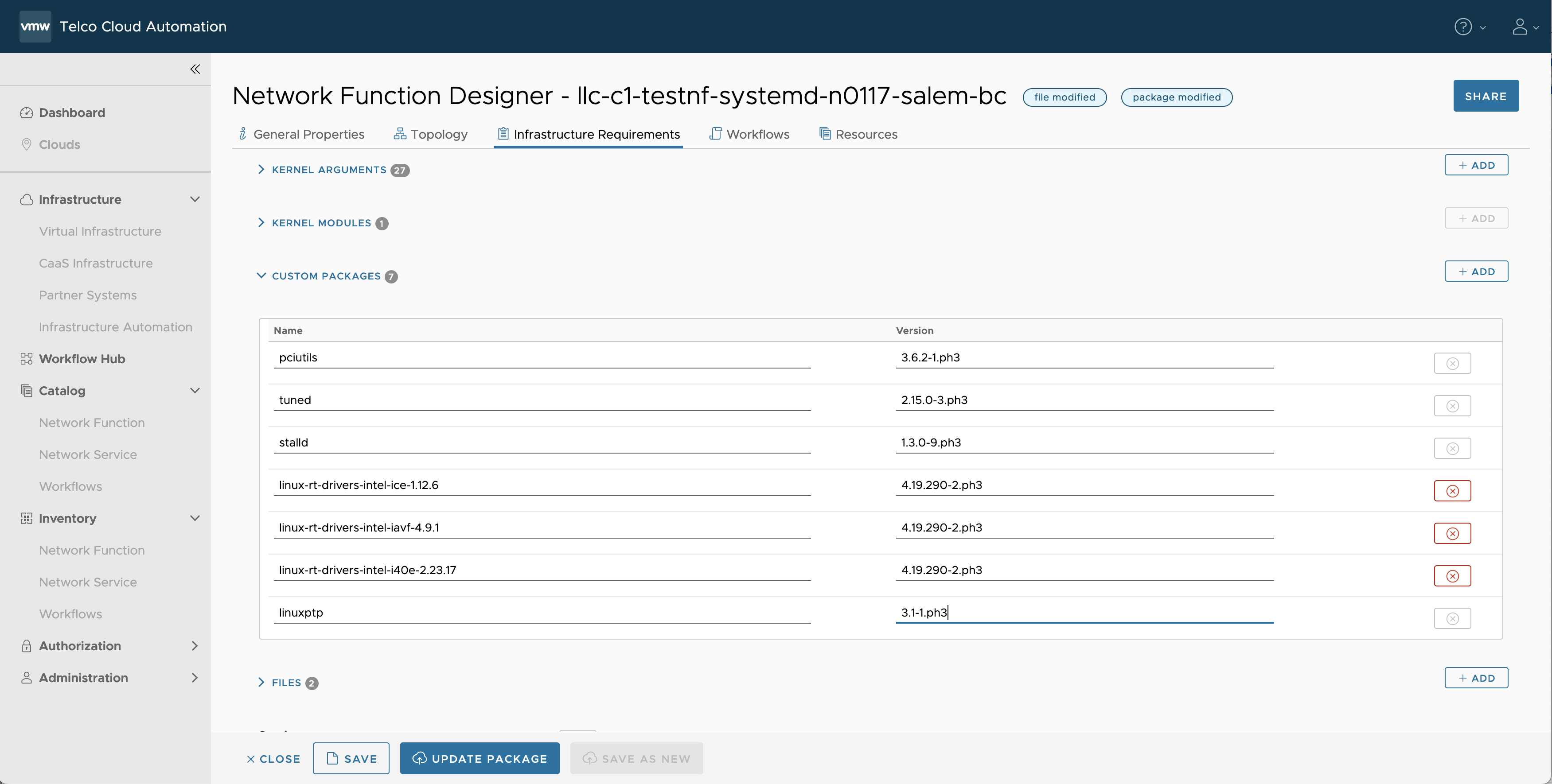
Note: When you add one or more PTP Devices, an entry for 'linuxptp' gets created in the Custom Packages section. Modify the linuxptp version as required.
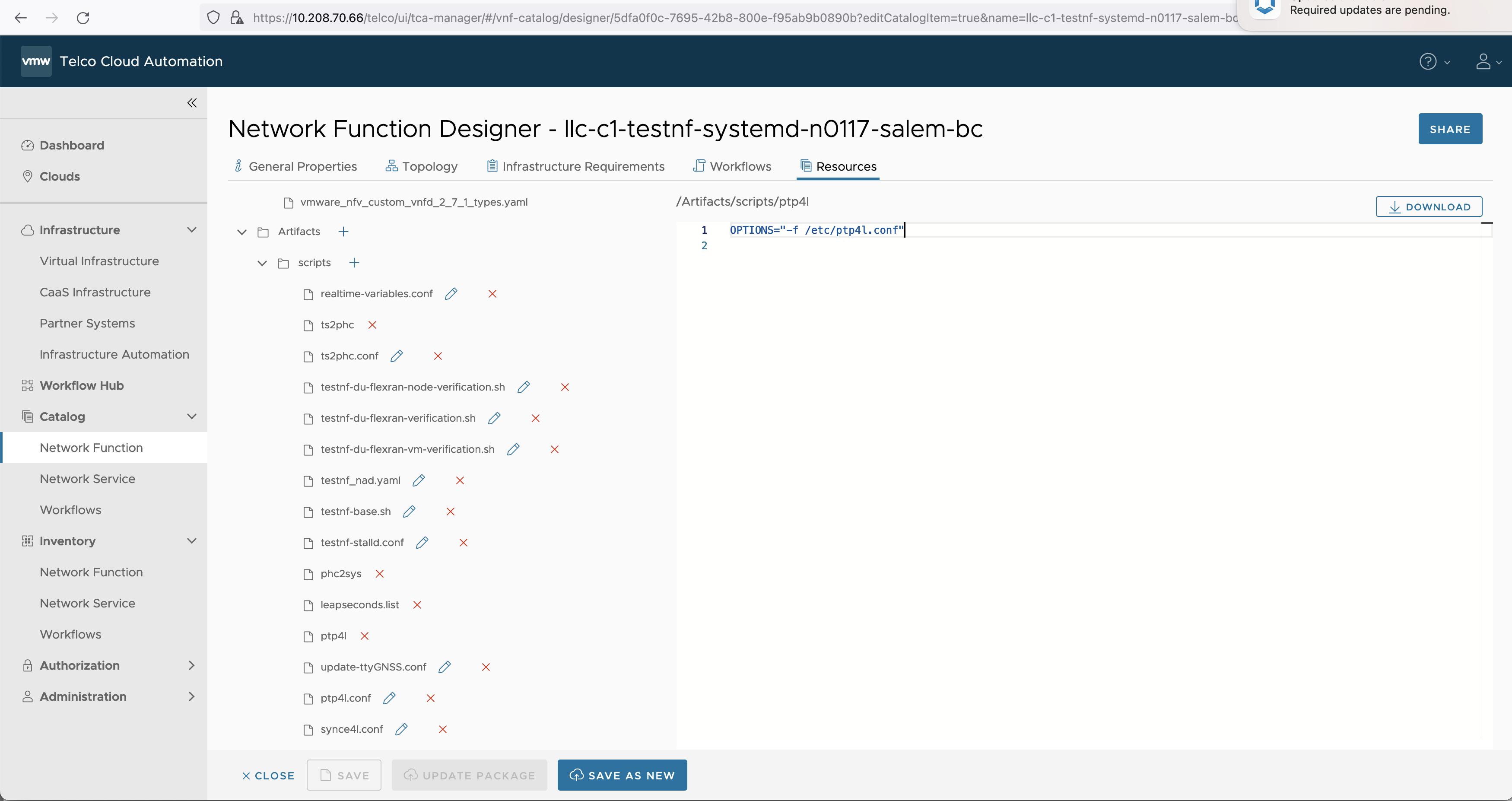
- Click the Resources tab.
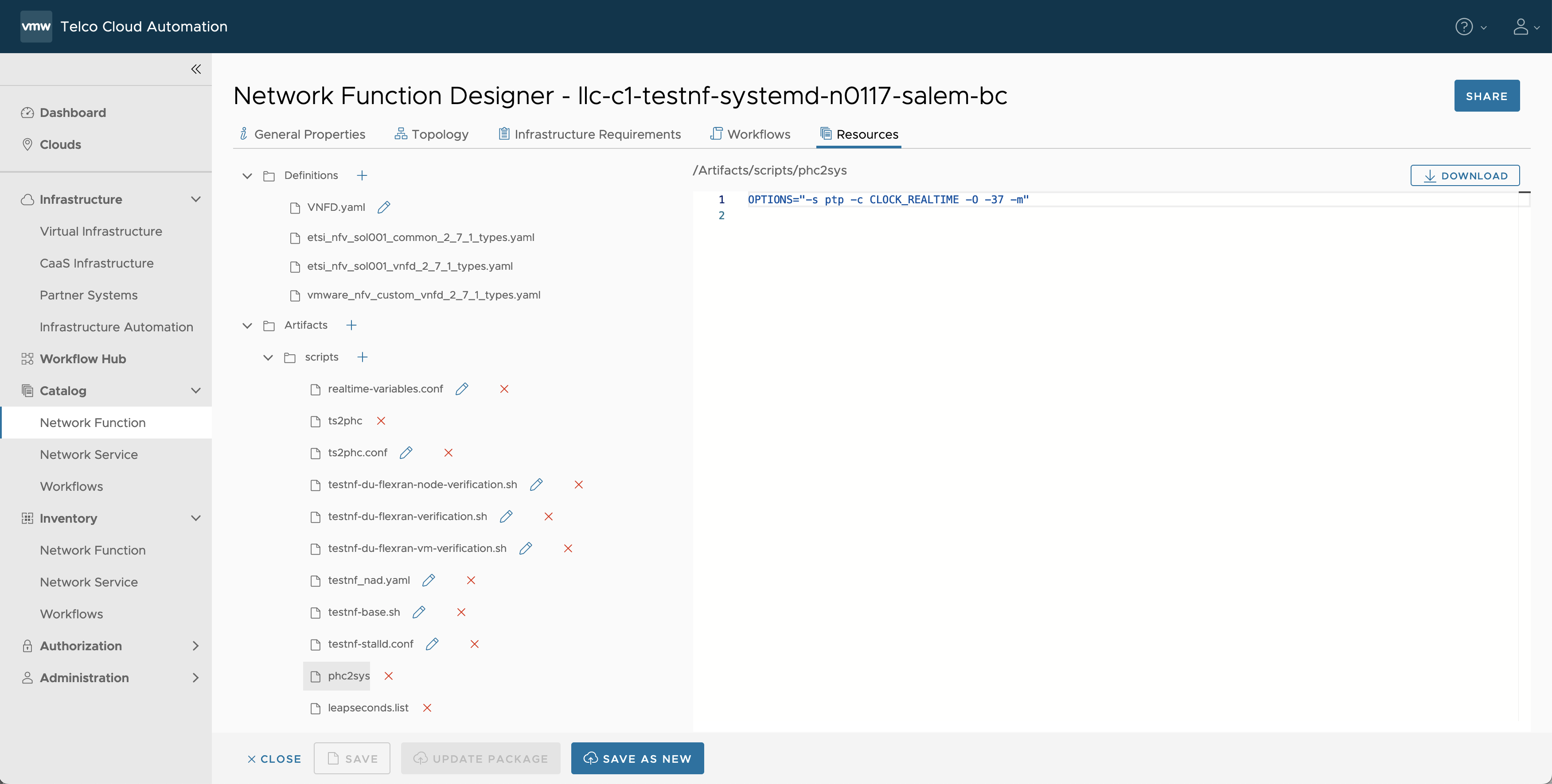
- Expand the Artifacts > scripts directory.
- Add the following configuration files by clicking the + symbol next to 'scripts':
-
phc2sys
OPTIONS="-s ptp -c CLOCK_REALTIME -O -37 -m"
ptp4l
OPTIONS="-f /etc/ptp4l.conf"
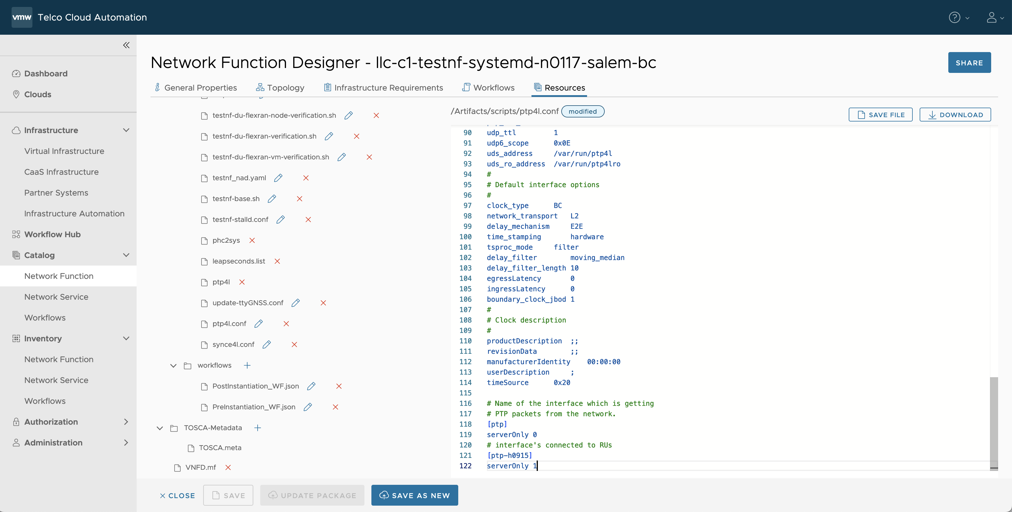
ptp4l.conf
Note: This sample configuration file is valid for linuxptp version 4.0-2.ph3
[global]
#
# Default Data Set
#
twoStepFlag     1
clientOnly      0
socket_priority     0
priority1       128
priority2       128
domainNumber        24
#utc_offset     37
clockClass      248
clockAccuracy       0x21
offsetScaledLogVariance 0xFFFF
free_running        0
freq_est_interval   1
dscp_event      0
dscp_general        0
dataset_comparison  G.8275.x
G.8275.defaultDS.localPriority  128
maxStepsRemoved     255
#
# Port Data Set
#
logAnnounceInterval -3
logSyncInterval     -4
operLogSyncInterval 0
logMinDelayReqInterval  -4
logMinPdelayReqInterval 0
operLogPdelayReqInterval 0
announceReceiptTimeout  3
syncReceiptTimeout  0
delayAsymmetry      0
fault_reset_interval    4
neighborPropDelayThresh 20000000
serverOnly      0
G.8275.portDS.localPriority 128
asCapable               auto
BMCA                    ptp
inhibit_announce        0
inhibit_delay_req       0
ignore_source_id        0
#
# Run time options
#
assume_two_step     0
logging_level       6
path_trace_enabled  0
follow_up_info      0
hybrid_e2e      0
inhibit_multicast_service   0
net_sync_monitor    0
tc_spanning_tree    0
tx_timestamp_timeout    300
unicast_listen      0
unicast_master_table    0
unicast_req_duration    3600
use_syslog      1
verbose         0
summary_interval    0
kernel_leap     1
check_fup_sync      0
#
# Servo Options
#
pi_proportional_const   0.0
pi_integral_const   0.0
pi_proportional_scale   0.0
pi_proportional_exponent    -0.3
pi_proportional_norm_max    0.7
pi_integral_scale   0.0
pi_integral_exponent    0.4
pi_integral_norm_max    0.3
step_threshold      0.0
first_step_threshold    0.00002
max_frequency       900000000
clock_servo     pi
sanity_freq_limit   200000000
ntpshm_segment      0
msg_interval_request    0
servo_num_offset_values 10
servo_offset_threshold  0
write_phase_mode    0
#
# Transport options
#
transportSpecific   0x0
ptp_dst_mac     01:1B:19:00:00:00
p2p_dst_mac     01:80:C2:00:00:0E
udp_ttl         1
udp6_scope      0x0E
uds_address     /var/run/ptp4l
uds_ro_address  /var/run/ptp4lro
#
# Default interface options
#
clock_type      BC
network_transport   L2
delay_mechanism     E2E
time_stamping       hardware
tsproc_mode     filter
delay_filter        moving_median
delay_filter_length 10
egressLatency       0
ingressLatency      0
boundary_clock_jbod 1
#
# Clock description
#
productDescription  ;;
revisionData        ;;
manufacturerIdentity    00:00:00
userDescription     ;
timeSource      0x20

# Name of the interface which is getting
# PTP packets from the network.
[ptp]
serverOnly 0
# interface's connected to RUs
[ptp-h0915]
serverOnly 1
Note: In the following ptp4l.conf file content, you can notice the interface name that you added in Step #4. In this example, only one RU is connected, so there is only one entry 'ptp-h0915'. If multiple RUs are connected, you need an entry for each RU (similar to ptp-h0915).
- Save the CSAR by clicking SAVE.
- Click UPDATE PACKAGE or SAVE AS NEW as appropriate.
- Click CLOSE.
- Instantiate the network function.

