


This section covers the physical architecture elements of the Telco Cloud, which is categorized into compute, storage, and network elements.
The Physical Infrastructure Tier differs when using Telco Cloud Platform Essentials and Telco Cloud Platform Advanced. Telco Cloud Platform Essentials does not include a software-defined networkting stack, so functionalities such as the Edge Pod are not supported with Telco Cloud Platform Essentials.
Compute Pod Architecture
The Telco Cloud design uses modular, reusable compute building blocks called Pods. Each Pod can include a combination of compute, storage, and networking platforms.
Compute pods are different from Kubernetes Pods.
A pod architecture provides hardware resources that allow for redundancy and availability. Each pod is connected to the underlay network fabric. This data center fabric (and the subsequent WAN) connects pods and facilitates efficient data transfer.
As a logical component of the Telco Cloud, the pod must be aligned physically to a rack within the data center. Edge and cell-site deployments have less host count than typical pod deployments.
The pod and rack mapping allows for a repeatable L2 design. VLANs that are created for the various management functions are re-used across pods or racks. However, the VLAN is not spanned across pods or racks. Each pod or rack uses locally significant VLANs to create a simple, reusable architecture.
A single rack can include a single or multiple smaller pods. However, when creating large pods that span across multiple racks, ensure the use of fault-domains. When using vSAN as the pod storage mechanism, the VLAN provisioning must also be planned to avoid L2 stretching where possible.
It is also common to separate the resources for control-plane and user-plane functions. To maximize resource utilization and provide maximum performance and throughput, user-plane functions are typically isolated from control-plane functions.
The following pod types are part of the Telco Cloud deployment:
Management pod
Compute pods (Control-Plane, User-Plane, or Mixed Mode)
Network edge pods (Telco Cloud Platform Advanced Only)
Near/Far edge pods
Cell sites
In smaller environments, some pod types can be combined to save resources. For example, the compute and network edge pods can be combined to create a single, shared network edge and compute pod.
Management Pod
The management pod is used for Telco Cloud management. The servers in the management pod host Virtual Infrastructure Servers, SDN Managers and edge nodes, Load Balancer controllers and edges components , Virtual Infrastructure Managers (VIMs), Telco Cloud Automation, and all the components from the Operations and Business Continuity tiers.
SDN Edge nodes or Service Edges / Engines from Load Balancers are typically deployed into the edge pod. However, for some use cases, a limited number of these are deployed into the management pod.
In case of Telco Cloud Platform Essentials, a Software-Defined Networking stack is not supported. Hence, overlay capabilities are not available and the deployment of SDN components is not required.
The Management Pod can be deployed using the components from Telco Cloud Platform Essentials or Advanced, based on your management pod requirements. Telco Cloud Platform Essentials RAN is not permitted for the Management Pod.
The management pod hosts the critical components of the Telco Cloud, so it must be deployed without any single point of failure across the server, storage, and networking configurations.
The management pod does not require the same level of feature-rich functionality as the workload domains. Ensure that the appliance hardware version is compatible with the Management versions. For more information, see the VMware Interoperability Matrix.
The management pod has its own Management VI, typically its own set of SDN Managers and a Load Balancer deployment to control the management pod. This setup enables full VI functionality (such as High Availability and Resource Schedulding) within the management pod and the ability to provide Network Overlay and Load Balancer services for applications within the management pod (such as the VIM and platform observability components).
Additional Resource VI Servers and SDN Managers that control the compute/edge pods must align with the recommended or compatible versions based on the Telco Cloud Platform release notes. The release bundle for Telco Cloud Platform specifies the required versions for VMware applications.
The management pod can be deployed using various methods. The two common methods of deploying the management pod:
Manual deployment of servers, VI Components, SDN Managers, and so on.
Automated deployment using tools (in-house or from VMware)
Compute Pods
Compute pods host the network functions (VNFs or CNFs). The compute pods can share a common design. However, due to the high throughput and performance requirements for user plane applications (such as UPF or other packet gateways), different hardware might be used to delineate between different types of compute pods.
All the resources such as VI Servers and SDN Managers that are required to run the compute pods are deployed in the management domain. With this architecture, only network functions and services run in a remote data center, while the components managing the infrastructure reside in the management pod.
If the SDN platform is not used, deploy Compute Pods based on Telco Cloud Platform Essentials. For overlay networks, deploy compute pods based on Telco Cloud Platform Advanced.
Edge Pods
Edge pods host SDN Edge nodes that enable north/south routing from the Telco Cloud to the upstream DC Gateway nodes. These edge nodes can run on hypervisor-based servers or Bare Metal servers.
Edge pods host stateful services and upstream BGP peering towards the network, while many components run in a distributed fashion. Egress traffic is handled by the edge pod.
Edge Pods are part of the Telco Cloud Platform architecture only when using Telco Cloud Platform Advanced.
Edge pods can be also used to deploy the Service Engine created by Load Balancer. The Load Balancer Controllers reside in the management domain while the Service engines can be distributed across the Edge pods.
Near and Far Edge Pods
Near and Far Edge pods are similar to compute pods. The most common difference is the size of the pod. While regular compute pods have 8, 16, or more hosts, the near/far-edge pods have lower host counts.
The far edge pods are commonly used in 5G Core or RAN use cases for distributed Network Functions such as UPF or CU nodes.
Cell Sites
A cell site is a single server rather than a pod. The cell site design is important from the connectivity and reusability perspective, enabling automation and consistency in the deployment of RAN applications such as the DU.
Cell sites from different hardware vendors or with different hardware (accelerator cards, Network Interface cards with onboard Global Network Satellite System interfaces) might have different physical designs.
Network Architecture
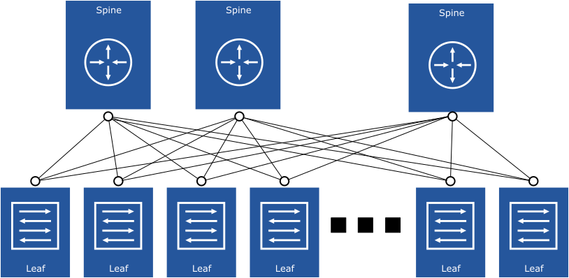
The DC fabric architecture is tightly coupled to the pod architecture. The physical design of the DC fabric can be an L2 fabric, a traditional 3-tier Data Center fabric, or a Leaf/Spine-based architecture. The network architecture might have an impact on the overall performance, convergence, and simplicity of operations. The pod architectures can integrate with multiple network architectures; however, the most common and recommended design is the Leaf/Spine architecture.
For a responsive and high-performance Telco Cloud, the physical network must have the following characteristics:
Simple design
Highly scalable
High bandwidth and interface count
Support for QoS, Low-Latency Queuing, and so on
Fault-tolerant design with no Single Point of Failure (SPOF)
Minimal or no over-subscription between the leaf and spine
In the Leaf/Spine architecture, the leaf switch is located within the rack and is responsible for the physical connectivity between the servers within the same rack. The rack can include more than one single Leaf switch for redundancy and networking resiliency
The physical network implementation can leverage L2 or L3-based transport. However, the L3 design is recommended as it is the most scalable and most commonly deployed architecture.
The spine switch provides single-hop connectivity between all Leaf switches. An IGP is used between the leaf and spine switches to ensure resiliency when a Leaf or Spine switch fails.
The main benefits of an L3 Transport Leaf/Spine-based architecture are as follows:
A wide range of products are available from various vendors
Commonly-used, highly-scalable, and cost-effective design
Enables re-use of configuration across leaf switches due to L2 termination and subsequent routing at the Leaf
L3 from leaf to spine; VLAN trunking is not required
The following diagram illustrates the rack design for compute pods. Due to cost and power constraints, cell sites do not have redundant leaf switches, ToR switches, or a network spine but rather operate independently. For more information, see Network Virtualization Design.
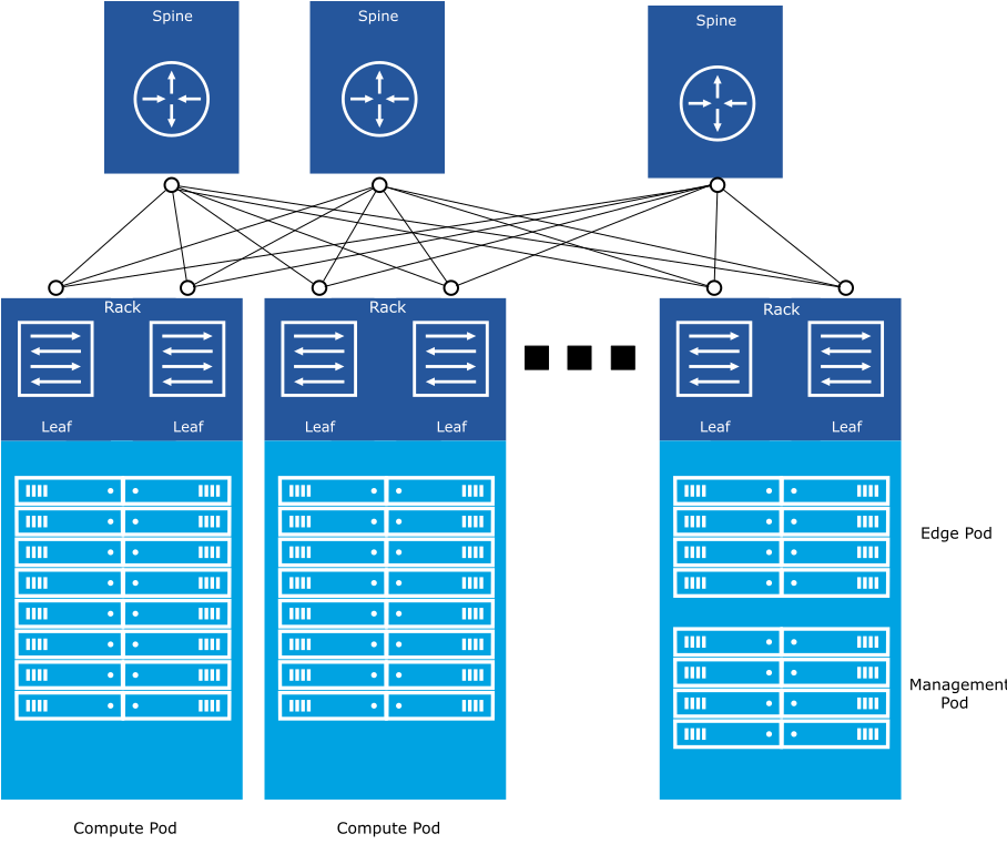
To prevent uplink over-subscription, the physical links between the leaf switches and the spine operate at a higher speed than those between the servers and the leaf switches. Over-subscription is calculated by the total leaf port bandwidth or total uplink bandwidth. For 16 servers in a rack with 25 GB connectivity (total 400 GB), a minimum of four 100 GB uplinks are required. The uplinks must be distributed equally and consistently to allow Equal-Cost Multipath (ECMP) capabilities.
Storage Architecture
For the Telco Cloud, VMware recommends using the Software-Defined Storage (SDS) approach. Software-Defined Storage integrates with the hypervisor to provide a Hyper Converged Infrastructure (HCI), where the disks on each physical host are leveraged to create a cluster wide datastore.
vSAN is the recommended storage architecture for the Telco Cloud. vSAN provides a highly scalable, high-performing, and fault-tolerant storage architecture to deliver storage to the network functions. vSAN uses the internal disks installed in each server to create a high-available clustered datastore that can be shared across all hosts within a vSphere cluster. For more information, see the vSAN Design Guide.
The Original Storage Architecture (OSA) vSAN model uses a combination of Solid-State Drives (SSDs) and Magnetic Disk Drives (HDDs) organized into storage tiers to create the datastore.
The Express Storage Architecture vSAN model (available in vSphere 8.0 or higher) uses storage pools instead of storage tiers. This model requires all NVME-based storage devices and higher-speed NICs for data transfer.
vSAN is the recommended storage architecture for the Telco Cloud but other storage solutions are also supported.
A wide range of external storage solutions such as iSCSI, NFS, and Fiber Channel are supported by the pods. For more information, see the VMware Compatibility Guide.
Some storage solutions might not offer direct cloud-native storage options, for example, RWX persistent volumes for Kubernetes. Ensure that the storage solution meets the requirements of the network functions being deployed to the Telco Cloud.
Telco Cloud Platform Advanced includes vSAN licensing for 1 Tib per core, whereas Telco Cloud Platform Essentials includes only 100Gib per core. Therefore, if the pods are deployed with vSAN, additional vSAN licenses may be required depending on the size of the vSAN datastore.
