Each type of workload places different requirements on the Tanzu Kubernetes cluster or worker node. This section provides the Kubernetes worker node and cluster sizing based on workload characteristics.
The ETSI NFV Performance & Portability Best Practices (GS NFV-PER 001) classifies NFV workloads into different classes. The characteristics distinguishing the workload classes are as follows:
Workload Classes |
Workload Characteristics |
|---|---|
Data plane workloads |
Data plane workloads cover all tasks related to packet handling in an end-to-end communication between Telco applications. These tasks are intensive in I/O operations and memory R/W operations. |
Control plane workloads |
|
Signal processing workloads |
Signal processing workloads cover all tasks related to digital processing, such as the FFT decoding and encoding in a cellular base station. These tasks are intensive in CPU processing capacity and are highly latency sensitive. |
Storage workloads |
Storage workloads cover all tasks related to disk storage. |
Workload Profile |
Workload Description |
|---|---|
Profile 1 |
Low data rate with numerous endpoints, best-effort bandwidth, jitter, or latency. Example: Massive Machine-type Communication (MMC) application |
Profile 2 |
High data rate with bandwidth guarantees only, no jitter or latency. Example: Enhanced Mobile Broadband (eMBB) application |
Profile 3 |
High data rate with bandwidth, latency, and jitter guarantee. Examples: factory automation, virtual and augmented reality applications |
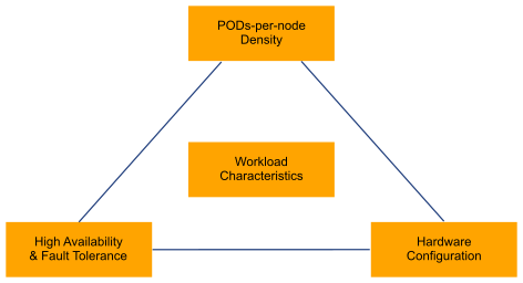
The following figure illustrates the relationship between workload characteristics and Kubernetes cluster design:

Limit the number of pods per Kubernetes node based on the workload profile, hardware configuration, high availability, and fault tolerance.
Control Node Sizing
By default, dedicate Control nodes to the control plane components only. All control plane nodes deployed have a taint applied to them.
This taint instructs the Kubernetes scheduler not to schedule any user workloads on the control plane nodes. Assigning nodes in this way improves security, stability, and management of the control plane. Isolating the control plane from other workloads significantly reduces the attack surface as user workloads no longer share a kernel with Kubernetes components.
By following the above recommendation, the size of the Kubernetes control node depends on the size of the Kubernetes cluster. When sizing the control node for CPU, memory, and disk, consider both the number of worker nodes and the total number of Pods. The following table lists the Kubernetes control node sizing estimations based on the cluster size:
Cluster Size |
Control Node vCPU |
Control Node Memory |
|---|---|---|
Up to 10 Worker Nodes |
2 |
8 GB |
Up to 100 Worker Nodes |
4 |
16 GB |
Up to 250 Worker Nodes |
8 |
32 GB |
Up to 500 Worker Nodes |
16 |
64 GB |
Kubernetes Control nodes in the same cluster must be configured with the same size.
Worker Node Sizing
When sizing a worker node, consider the number of Pods per node. For low-performance pods (Profile 1 workload), ensuring Kubernetes pods are running and constant reporting of pod status to the Control node contributes to the majority of the kubelet utilization. High pod counts lead to high kubelet utilization. Kubernetes official documentation recommends limiting Pods per node to less than 100. This limit can be set high for Profile 1 workload, based on the hardware configuration.
Profile 2 and Profile 3 require dedicated CPU, memory, and vNIC to ensure throughput, latency, or jitter. When considering the number of pods per node for high-performance pods, use the hardware resource limits as the design criteria. For example, if a data plane intensive workload requires dedicated passthrough vNIC, the total number of Pods per worker node is limited by the total number of available vNICs.
As a rule, allocate 1 vCPU and 10 GB memory for every 10 running Pods for CPU and memory for generic workloads. In scenarios where 5G CNF vendor has specific vCPU and memory requirements, the worker node must be sized based on CNF vendor recommendations.
Tanzu Kubernetes Cluster Sizing
When you design a Tanzu Kubernetes cluster for workload with high availability, consider the following:
Number of failed nodes to be tolerated at once
Number of nodes available after a failure
Remaining capacity to reschedule pods of the failed node
Remaining Pod density after rescheduling
Based on failure tolerance, Pods per node, workload characteristics, worker nodes to deploy for each workload profile can be generalized using the following formula:
Worker Node (Z)= (pods * D) + (N+1)
Z specifies workload profile 1 - 3
N specifies the number of failed nodes that can be tolerated
D specifies the max density. 1/110 is the K8s recommendation for generic workloads.
For example, if each node supports 100 Pods, building a cluster that supports 100 pods with a failure tolerance of one node requires two worker nodes. Supporting 200 pods with a failure tolerance of one node requires three worker nodes.
Total Worker node = Worker Nodes (profile 1) + Worker Nodes (profile 2) + Worker Nodes (profile 3)
Design Recommendation |
Design Justification |
Design Implication |
|---|---|---|
Dedicate the Kubernetes Control node to Kubernetes control components only. |
Improved security, stability, and management of the control plane. |
|
Kubernetes Control node VMs in the same cluster must be sized identically based on the maximum number of Pods and nodes in a cluster. |
|
Idle resources as only the Kubernetes API server runs active/active under the steady state. |
Set the maximum number of Pods per worker node based on the HW profile. |
|
K8s cluster-wide setting does not work properly in a heterogeneous cluster. |
Use failure tolerance, workload type, and pod density to plan the minimum cluster size. |
|
High failure tolerance can lead to low server utilization. |