


The network virtualization design uses the vSphere Distributed Switch (VDS) and associated features such as the Converged VDS (C-VDS) through the NSX and vSphere integration.
Network Virtualization Design Goals
The following high-level design goals apply regardless of your environment:
Meet diverse needs: The network must meet the diverse requirements of different entities in an organization. These entities include applications, services, storage, administrators, and users.
Reduce costs: Server consolidation reduces network costs by reducing the number of required network ports and NICs, but a more efficient network design is required. For example, configuring two 25 GbE NICs might be more cost-effective than four 10 GbE NICs.
Improve performance: You can achieve performance improvement and decrease the maintenance time by providing sufficient bandwidth, which in turn reduces the contention and latency.
Improve availability: A well-designed network improves availability by providing network redundancy.
Support security: A well-designed network supports an acceptable level of security through controlled access and isolation, where required.
Enhance infrastructure functionality: You can configure the network to support vSphere features such as vSphere vMotion, vSphere High Availability, and vSphere Fault Tolerance.
In specific use-cases such as D-RAN deployments, the support of enhanced infrastructure functionality may be different. In single-node deployments, elements such as vMotion and vSphere HA are removed in favor of network performance and throughput.
Network Virtualization Best Practices
The following network virtualization best practices can be considered throughout your environment:
Separate the network services to achieve high security and better performance. This requires multiple vSwitches to differentiate between management functions and workload traffic.
Use the Network I/O Control and traffic shaping to guarantee bandwidth to critical VMs. During the network contention, these critical VMs receive a high percentage of the bandwidth.
Note:Do not use this best practice for user plane telco workloads as it might increase latency and impact overall throughput.
Separate the network services on a vSphere Distributed Switch by attaching them to port groups with different VLAN IDs.
Keep vSphere vMotion traffic on a separate network. When a migration using vSphere vMotion occurs, the memory of the guest operating system is transmitted over the network. You can place vSphere vMotion on a separate network by using a dedicated vSphere vMotion VLAN and a dedicated Telco Cloud Platform stack for vMotion.
Ensure that physical network adapters that are connected to the same vSphere Standard or Distributed Switch are also connected to the same physical network.
Network Virtualization Segmentation
In many cases, separating different types of traffic is recommended for access security and to reduce the contention and latency.
High latency on any network can have a negative impact on the performance. Some components are more sensitive to high latency than others. For example, high latency IP storage and the vSphere Fault Tolerance logging network can negatively affect the performance of multiple VMs.
While a single vSwitch design can deliver the appropriate segmentation, segmentation at the vSwitch level for management functions provides increased resiliency to the platform and maximizes overall throughput at the cost of additional NICs or ports. By segmenting the following management functions, the platform can maximize the overall throughput of the infrastructure:
ESXi Management
vMotion
vSAN (OSA or ESA)
IP Storage
According to the application or service, high latency on specific VM networks can also negatively affect performance. Determine which workloads and networks are sensitive to high latency by using the information gathered from the current state analysis and by interviewing key stakeholders and SMEs. Determine the required number of network cards, ports, uplinks, and VLANs depending on the type of traffic.
vSphere Distributed Switching
The core of any virtualized infrastructure is the networking that backs the VMs and the ESXi hosts.
Within vSphere environment, VMware provides two types of virtual switches: standard switch and vSphere-managed Virtual Distributed Switch (vSphere VDS). The Converged VDS that integrates NSX and vSphere Distributed Switch functionalities is based on the underlying vSphere VDS.
The vSphere Distributed Switch functions as a single switch to which all hosts in a workload domain are connected. This architecture allows network configurations to be consistently applied across all attached hosts.
The vSphere Distributed Switch comprises two components:
Port groups: The port groups, to which the VMs are connected, enable inter-VM communication. Each port group can have its own configuration such as Port Group name, VLAN, teaming policies, and so on.
Uplink adapters: The uplink adapters determine the physical interfaces that are used to connect a VDS to the underlay network. The uplink configuration can incorporate elements such as Link Aggregation Control Protocol (LACP).
vSphere Distributed Switch instances offer several enhancements compared to the legacy standard virtual switches. Because vSphere Distributed Switch instances are centrally created and managed, the virtual switch configuration can be made consistent across ESXi hosts. Centralized management saves time, reduces mistakes, and lowers operational costs.
The number of vSwitches deployed throughout the Telco cloud depends on various factors such as design constraints, physical NIC or port count, throughput requirements, network redundancy requirements, and so on.
The following vSwitch design shows the dual vSwitch model for the management and general VNF/CNF workload clusters.
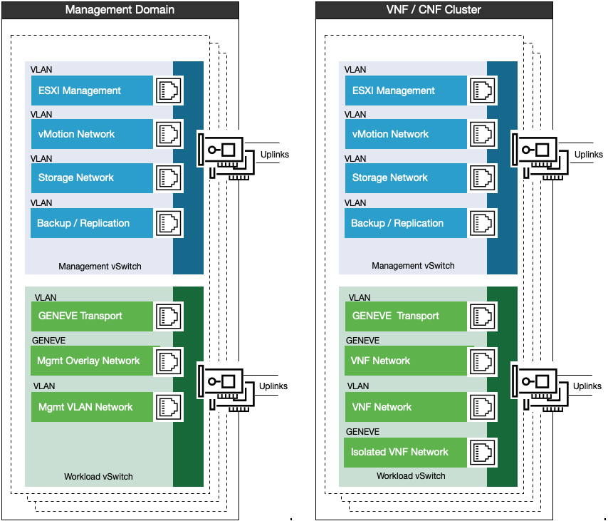
In this dual vSwitch model, the management vSwitch is used for host management, with VLAN for ESXi, vMotion, Storage (vSAN or IP storage) and backup/replication. The workload vSwitch is used only for workload traffic, a Similar design can also be used for the edge pods.
Two vSwitches are used to separate management traffic from workload traffic even if the hosts are not prepared with NSX. This would remove the GENEVE and Mgmt Overlay segments but the Management VLAN networks exist regardless of the state of the NSX in the management domain.
If both vSAN and other storage platforms are both deployed, separate VLANs must be created for different storage switches.
The management vSwitch must leverage Network I/O control to provide guarantees for the storage network. If vSAN ESA is used, each network uplink must be at least 25 GB.
The following vSwitch design shows the single vSwitch model for the general VNF/CNF workload clusters
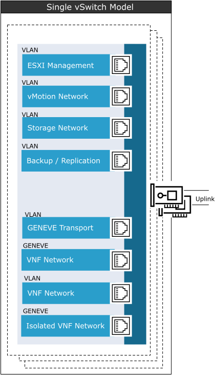
In the single vSwitch model, a common vSwitch is used for host management, with VLAN for ESXi, vMotion, Storage (vSAN or IP storage), backup/replication, and workload traffic.
When using a single vSwitch, configure Network I/O control to ensure guarantees to both management and workload traffic.
The vSwitch allows the separation of different traffic types, providing access security and reducing the contention and latency.
High latency on any network can negatively affect the performance. Some components are more sensitive to high latency than others. For example, high latency IP storage and the vSphere Fault Tolerance logging network can negatively affect the performance of multiple VMs.
Depending on the CSP requirements, constraints, and hardware, you can use either of these vSwitch models for the deployment and configuration of the network virtualization design. Ensure that you understand the impact.
vSwitch and NUMA Considerations
For User-Plane intensive workloads, such as the UPF, the alignment of the networking with the CPUs used for VM execution is important to maximize performance.
To perform NUMA alignment on the vSwitching layer, at least two physical NICs are required. One NIC must be installed in a PCI slot that aligns to socket 0 (NUMA Node 0), and the other must be installed in a PCI slot that aligns to socket 1 (NUMA Node 1).
When using NSX Enhanced Data Path (EDP) with multiple NICs that are NUMA aligned, NSX ensures (through the converged VDS) that the traffic is NUMA aligned. The network traffic is aligned with the NUMA node from where the VM vCPUs and memory are allocated.
For fully NUMA redundant designs, 4 NICs (2 per NUMA) are required.

NIC Teaming and Failure Detection
NIC teaming policies increase the network bandwidth available to network paths and provide redundancy by avoiding single points of failure for network segments.
NIC teaming is achieved by assigning multiple physical NICs to a virtual switch. Any NIC can be used. However, the NIC team built using ports from multiple NICs and motherboard interfaces provides optimal protection, decreases the chances of failure, and aligns with the NUMA considerations.
In addition to NIC teaming, the Telco Cloud administrators can use the following types of failure detection methods:
Link status only:
Relies only on the link status that the network adapter provides.
Detects failures such as removed cables and physical switch power failures.
Link status will not detect switch ports put into a blocking state by the Top-Of-Rack Switch, nor will it detect VLAN mismatches between the ESXi host and the switch.
Beacon probing: Sends out and listens for Ethernet broadcast frames or beacon probes that physical NICs send to detect link failure in all physical NICs in a team. ESXi hosts send beacon packets every second. Beacon probing is most useful to detect failures in the physical switch closest to the ESXi host, where the failure does not cause a link-down event for the host. However, to properly function, beacon probing requires three uplinks. Link Status is the recommended failure detection mechanism.
Network I/O Control
When Network I/O Control (NIOC) is enabled, the distributed switch allocates bandwidth for different traffic types. vSphere 6.0 and later supports NIOC version 3.
When network contention occurs, Network I/O Control enforces the share value specified for different traffic types. Network I/O Control applies the share values set to each traffic type. Hence, less important traffic, as defined by the share percentage or network pools, is throttled while granting more network resources to more important traffic types.
Network I/O Control supports bandwidth reservation for system traffic based on the capacity of physical adapters on an ESXi host. It also enables fine-grained resource control at the VM network adapter. Resource control is similar to the CPU and memory reservation model in vSphere DRS.
NIOC is enabled on the management switches to assign bandwidth reservations for vMotion or vSAN. However, it can add latency that might result in a reduction in network performance. Hence, NIOC is not recommended on workload vSwitches.
TCP/IP Stacks for vMotion
Use the vMotion TCP/IP stack to isolate the traffic for vSphere vMotion and to assign a dedicated default gateway for the vSphere vMotion traffic.
By using a separate TCP/IP stack, you can manage vSphere vMotion and cold migration traffic according to the network topology, and as required by your organization.
Route the traffic for the migration of VMs (powered on or off) by using a default gateway. The default gateway is different from the gateway assigned to the default stack on the ESXi host.
Assign a separate set of buffers and sockets.
Avoid the routing table conflicts that might appear when many features are using a common TCP/IP stack.
Isolate the traffic to improve security.
Recommended Network Virtualization Design
Design Recommendation |
Design Justification |
Design Implication |
Domain Applicability |
|---|---|---|---|
Use two physical NICs for vSwitch uplinks on all vSwitches. |
Provides redundancy to all port groups. |
None |
Compute clusters, VNF, CNF, C-RAN, Near/Far Edge, and NSX Edge |
Provide NUMA-aligned uplinks to the workload vSwitch. |
Maximizes workload throughput in dual-socket servers |
Requires at least one or two uplink ports per NUMA for maximum redundancy |
Compute clusters, VNF, CNF, C-RAN, Near/Far Edge, and NSX Edge |
Use the Route based on the physical NIC load teaming algorithm for all port groups. |
Reduces the complexity of the network design Increases resiliency and performance. |
None |
Compute clusters, VNF, CNF, C-RAN, Near/Far Edge, and NSX Edge |
Separate uplinks across physical cards |
Provides high availability in the event of a NIC failure |
Requires at least two NIC cards per NUMA if redundancy is required per NUMA |
Compute clusters, VNF, CNF, C-RAN, Near/Far Edge, and NSX Edge |
Use vSphere Distributed Switches. |
Simplifies the management of the virtual network. |
Migration from a standard switch to a distributed switch requires a minimum of two physical NICs to maintain redundancy. |
Compute clusters, VNF, CNF, C-RAN, Near/Far Edge, and NSX Edge D-RAN or C-RAN deployments through cell site groups |
Use Converged VDS when using NSX |
Allows NSX functionality to be leveraged as part of the workload vSwitches |
Converged VDS for workload |
Compute clusters, VNF, CNF, C-RAN, Near/Far Edge, and NSX Edge Workload vSwitches only |
Use ephemeral port binding for the management port group. |
Provides the recovery option for the vCenter Server instance that manages the distributed switch. |
Port-level permissions and controls are lost across power cycles, and no historical context is saved. |
Management Domain Management vSwitch Only |
Use static port binding for all non-management port groups. |
Ensures that a VM connects to the same port on the vSphere Distributed Switch. This allows for historical data and port-level monitoring. |
None |
Compute clusters, VNF, CNF, C-RAN, Near/Far Edge, and NSX Edge |
Enable Network I/O Control on non-workload distributed switches. |
Increases the resiliency and performance of the network |
If configured incorrectly, Network I/O Control might impact the network performance for critical traffic types. |
Compute clusters VNF, CNF, C-RAN, Near/Far Edge, and NSX Edge Management vSwitch Only |
Use the vMotion TCP/IP stack for vSphere vMotion traffic. |
By using the vMotion TCP/IP stack, vSphere vMotion traffic can be assigned a default gateway on its own subnet and can go over Layer 3 networks. |
None |
Compute clusters, VNF, CNF, C-RAN, Near/Far Edge, and NSX Edge Management vSwitch only |
Configure all vSwitches with 9000 MTU. |
Increases throughput for vMotion / vSAN and workloads |
Requires ToR switches also to support Jumbo Frames |
Compute clusters, VNF, CNF, C-RAN, Near/Far Edge, and NSX Edge Both vSwitches must be configured with Jumbo Frames. |
Use Link status as the link failure detection mechanism. |
Beacon probing requires 3 NICs in a NIC team. |
Certain types of failures further down the path in the underlay network cannot be detected. Monitoring for the physical networking must be able to capture and respond to those failures. |
Compute clusters, VNF, CNF, C-RAN, Near/Far Edge, and NSX Edge Both vSwitches must be configured with Link Status. |
RAN vSwitch Design
In a RAN environment, specifically the D-RAN environment at cell sites, the vSwitch design is different from the management and general cluster design.
In cell site ESXi hosts, create a single virtual switch per cell site group. The virtual switch can manage each type of network traffic and configure a port group to simplify the configuration and monitoring.
When leveraging Telco Cloud Automation to onboard RAN cell sites, the concept of a Cell Site Group is created. This Cell Site Group defines the vSwitch configuration. When the host is added to the cell site group, the vSwitch configuration is applied across all hosts in the cell site group.
The Distributed vSwitch concept eases the management burden by treating the network as an aggregated resource. Individual host-level virtual switches are abstracted into one large VDS spanning multiple hosts. In this design, the data plane remains local to each VDS but the management plane is centralized.

The management traffic on the RAN Cell Site must be less than 150ms from the ESXi host back to the vCenter.
Follow these considerations for the RAN cell sites:
The maximum number of unique vSwitches that are supported on a single vCenter is 128.
Each VDS can manage up to 2000 hosts. However, the design for each Cell Sites group consumes a unique vSwitch.
RAN SR-IOV Considerations
Due to the challenges in resource optimization, vMotion, and so on, SR-IOV is not recommended for the Core or Edge of the Telco Cloud. However, in the RAN (especially D-RAN) where a single server is deployed, SR-IOV can improve overall RAN performance.
SR-IOV is a specification that allows a single Peripheral Component Interconnect Express (PCIe) physical device under a single root port to appear as multiple separate physical devices to the hypervisor or the guest operating system.
SR-IOV uses Physical Functions (PFs) and Virtual Functions (VFs) to manage global functions for the SR-IOV devices. PFs are full PCIe functions that configure and manage the SR-IOV functionality. VFs are lightweight PCIe functions that support data flow but have a restricted set of configuration resources. The number of VFs provided to the hypervisor or the guest operating system depends on the device. SR-IOV enabled PCIe devices require appropriate BIOS, hardware, and SR-IOV support in the guest operating system driver or hypervisor instance.
In vSphere 8.0, the number of VFs that can be attached to a VM is increased to accommodate RAN deployment requirements. For more information about configuration maximums, see VMware Configuration Maximums.
In vSphere, a VM can use an SR-IOV virtual function for networking. The VM and the physical adapter exchange data directly without using the VMkernel stack as an intermediary. Bypassing the VMkernel for networking reduces the latency and improves the CPU efficiency for high data transfer performance. As the VM does not have access to the Physical Function, a message box or similar solution is created to allow the VFs that are exposed to the guest OS to send communication messages to the Physical Function. This allows for hardware configuration or alerting messages from within the Guest OS back to ESXi.
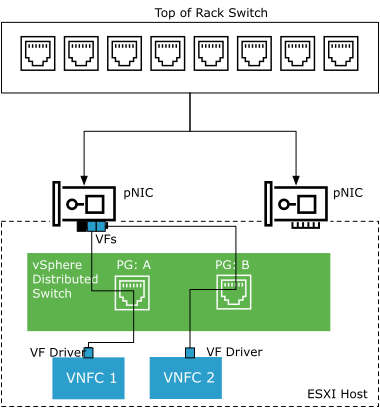
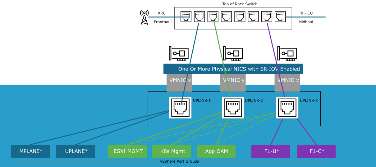
SR-IOV makes the vSwitch design in a RAN cell site different from the traditional vSwitch model. The following diagram illustrates the VDS design in a RAN cell site:
In the Cell Site, the layout and configuration of the vSwitch is different. Because of the SR-IOV interfaces for Fronthaul (from RU to DU) and Midhaul (from DU to CU), fixed uplinks are used for different connectivity requirements.
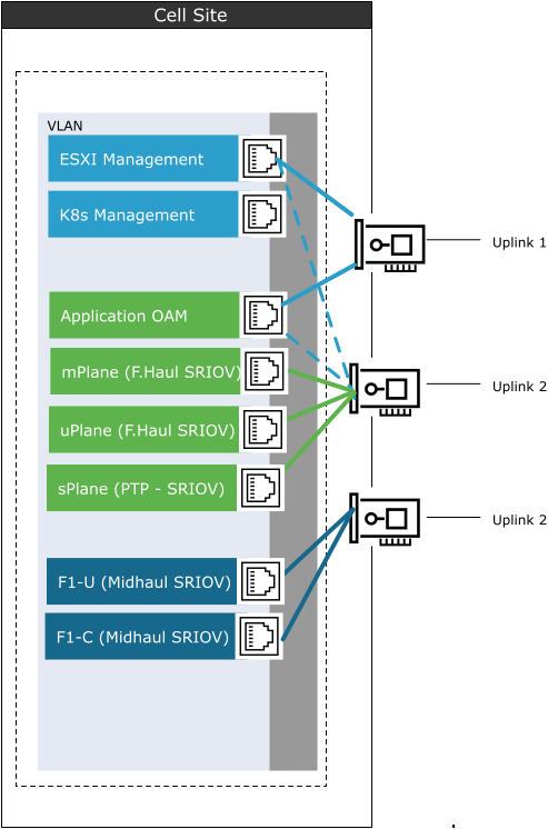
The following diagram illustrates an alternate representation of the RAN Cell Sites switch:
PTP timing is an important consideration in the RAN. In the model shown above, the PTP Grandmaster is connected to the Top of Rack switch. This design is typical for LLS-C3 type configurations.
Depending on the hardware installed and the workload, the PTP Timing interface can be configured at the cell site in one of the two ways:
Passthrough of the PF to the worker node: This must be the first physical interface on the NIC (the first port on a specific NIC). When using this configuration, an unused VMNIC port must be used for PT.
PTP over VF: In this method, the S-Plane is passed to the worker node over an additional SR-IOV interface. The S-Plane interface is carried over VMNIC.
For more information about PTP configuration, see A1: PTP Overview in the Telco Cloud Automation User Guide.
In an LLS-C1 configuration, the DU nodes connect directly to additional ports on the ESXi server. The NICs need to provide an onboard GNSS solution to take clocking directly from a GPS antenna rather than from the Top of Rack Switch.
This model requires additional NICs on the physical server.
When using SR-IOV along with NUMA alignment, Telco Cloud Automation ensures that the SR-IOV VF is taken from a physical NIC that is aligned to the NUMA node where the VM will be placed.
The option to relax the NUMA alignment can be selected. However, this is used when the SR-IOV VF is used for PTP and not for user plane interfaces.
RAN Network Virtualization Recommendations
Design Recommendation |
Design Justification |
Design Implication |
|---|---|---|
Use two physical NICs in Cell Site ESXi host for workloads. |
Provides redundancy to all port groups |
None |
Use a minimum of one SR-IOV VF or physical NIC in Cell Site ESXi hosts for PTP time synchronization. |
Provides time synchronization service |
Needs to be determined if NIC card can provide PTP over SR-IOV VF or if pass-through is necessary |
Create Cell Sites using the Cell Site Grouping mechanism in Telco Cloud Automation |
Provides a central configuration point for adding cell site hosts to the environment |
|
When using multiple cell site groups to segment a market or large RAN deployment, be aware of the 128 vSwitch limit. |
Allows for proper dimensioning of cell site groups. |
Maximum 128 vSwitches supported in a single vCenter. These vSwitches needs to be shared between management vSwitches, workloads, and RAN |
Use at least 3 ports for the vSwitch uplink. |
Allows separation of management, fronthaul, and midhaul traffic |
Requires additional ports |
Ensure that fronthaul and midhaul ports are assigned to different uplinks in the Port Group configuration. |
Separates the fronthaul and midhaul traffic, allowing for maximal throughput |
