


A classic 3-layer conceptual architecture for the Telco Edge deployment is a hierarchical model that consists of a group of Far Edge sites that aggregate into a Near Edge site and a group of Near Edge sites that aggregate into a Core site.

The maximum number of Edge sites in a specific group is governed by the maximum scale supported by the respective management components. In addition to functioning as a traffic aggregation point, a higher layer site also functions as a management layer for the lower tiers, as appropriate. Therefore, the management component for all the Far Edge sites aggregating into a Near Edge is usually located in the specific Near Edge site. But, the management component for the Near Edge site can be located locally for expediency reasons.
Each of the Edge sites is individually addressable and the workloads can be placed in the correct Edge site. Each Edge site also has a local breakout capability to the Internet. Therefore, Internet bound traffic does not have to traverse through the Telco network before being routed to its destination.
Telco Edge Reference Model
To optimize the Edge deployment to run workloads without significant management overhead, the management plane functionality for the Edges is usually implemented in a site remote to the Edge. While this imposes some constraints on networking (including link availability and end-to-end latency), this model of remote management is useful for constrained environments such as Far Edges.
The benefit of this model is the ease and simplicity with which the entire Telco infrastructure can be administered. Instead of having to connect to each Edge site to configure and control the resources at that site, users can access the centralized management at the Core data center, which can give them access to all the Edge sites under its purview.
In some deployments, the number of Far Edge sites can be very large, running into several thousands. In such cases, a hierarchical management approach is optimal. Irrespective of the model of aggregation, an architectural principle that an edge site is managed from a central site is used. This reference architecture considers a model where a group of edge sites, both Telco Near and Far edge, are managed from a single management instance at a core site. This is depicted in following figure.
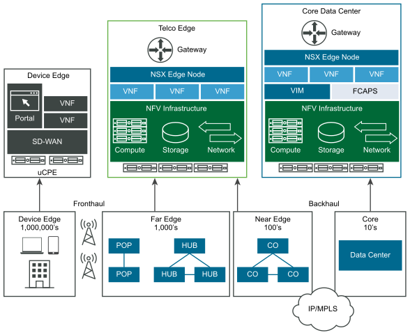
The two edge types are collapsed into a single Telco Edge that is managed from a Core data center. The components of a Telco edge representing the NFV infrastructure that includes compute, networking, and storage are depicted in the preceding diagram.
Scope of this Reference Architecture
vCloud NFV Edge Reference Architecture considers both near and far edges as a single edge type and one or groups of these edge sites are managed remotely from the core site. We use the term "Region" to indicate a group of Edge Sites.
The Core site is connected to the Edge site through a Telco network generically described as metro/WAN in this reference architecture. Examples of such networks include Metro Ethernet, MPLS and so on. However, the actual technology used is not pertinent to this reference architecture. Because the core sites and the edge sites are connected over Layer 3, it is important that a routed network topology exists between the sites.
Layer 2 networks are expected to be terminated at the provider Edge (PE) routers at the Core and at the Edge data centers. A Layer 3 path and connection between the core PE router and the Edge PE router through the metro or WAN network is assumed to be configured beforehand. It is important to ensure that a sufficient bandwidth at low latency is available for the Core site and Edge site connectivity.
