


The networking of the Resource Pod is highly dependent on the network topology that is required by the telco workloads, which tenants deploy. Tenant workloads require a certain set of networking building blocks.
Logical Switch
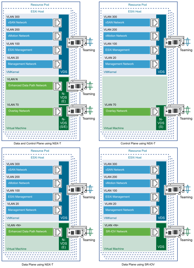
Logical switches are the layer 2 networks created by NSX-T Data Center to provide connectivity between its services and the VMs. Logical switches form the basis of the tenant networks in the vCloud NFV platform. The primary component in the data plane of the transport nodes is N-VDS. N-VDS forwards traffic between components running on the transport node (that is between VMs) or between VMs and the physical network. In the latter case, N-VDS must own one or more physical interfaces (physical NICs) on the transport node. As with other virtual switches, an N-VDS cannot share a physical interface with another N-VDS. It can coexist with another N-VDS each using a separate set of physical NICs.
Logical Routing
The NSX-T Data Center platform provides the ability to interconnect both virtual and physical workloads that are deployed in different logical layer 2 networks. NSX-T enables the creation of network elements like switches and routers as software logical constructs and embeds them in the hypervisor layer, abstracted from the underlying physical hardware.
East-West Traffic
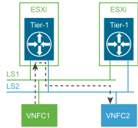
Configuring a logical router through the NSX Manager instantiates a logical router on each hypervisor. For the VNFs hosted on the same hypervisor, the East-West traffic does not leave the hypervisor for routing. The logical router is also responsible for routing East-West traffic between hypervisors.
North-South Traffic
In addition to providing optimized distributed and centralized routing functions, NSX-T Data Center supports a multi-tiered routing model with logical separation between the provider routing function and the tenant routing function. This way, the concept of multitenancy is built in the routing model. The top-tier logical router is called a Tier-0 router, whereas the bottom-tier logical router is called a Tier-1 router. Northbound, the Tier-0 logical router connects to one or more physical routers or layer 3 switches and serves as an on/off ramp to the physical infrastructure. Southbound, the Tier-0 logical router connects to one or more Tier-1 logical routers.
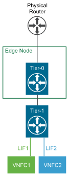
This model also eliminates the dependency on a physical infrastructure administrator to configure or change anything on the physical infrastructure when a new tenant is configured in the data center. For a new tenant, the Tier-0 logical router simply advertises the new tenant routes that are learned from the tenant Tier-1 logical router on the established routing adjacency with the physical infrastructure.
