


In the Micro-segment Wheel view, the blue lines denote the outgoing flows, the yellow lines denote the incoming flows, and the green lines denote the flows that are bidirectional.
Click any of the segments to view its details, and to modify the scope, click Modify Scope in the top panel.
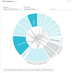
For better visibility and ease of use, you can only see 10 segments at a time. If you have more than 10 segments, then the extra segments are hidden under one large segment located next to Other Entities. To see the list of hidden segments point to the large segment next to Other Entities and you see the list of hidden segments.
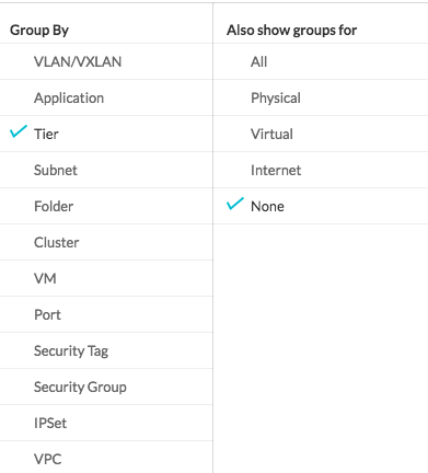
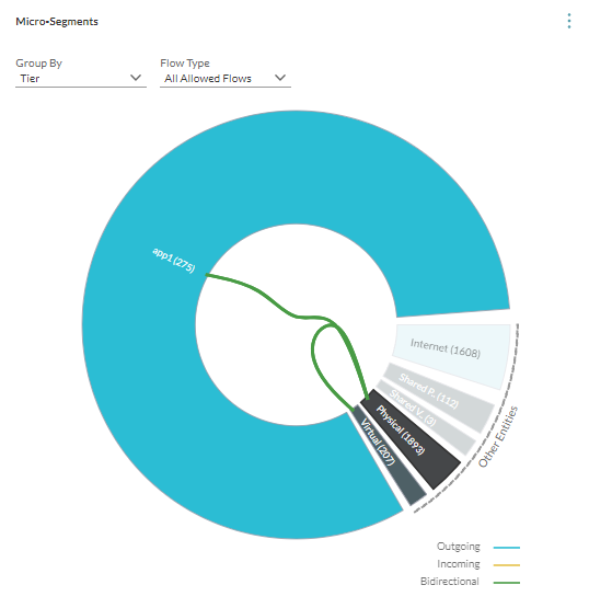
You can also analyze the flows by creating subgroups as per Physical, Other Virtual, and Internet categories.
Each group is expanded into a wedge. In the following topology, the wedge for Physical group is seen.
The Flows pin shows that the flows for different time intervals separated by ports. You can either view all the flows or view the flows between two entities. You can filter the flows by Allowed and Blocked flows. You can view flows by either Total Bytes or by Allowed Session Count. For the flows that are protected by a firewall, a Protected by Firewall sign is used to denote that the flows in that port that are protected by a firewall.
The planning for a scope such as an entire data center or a cluster selects flows that have VMs or Physical Servers (identified by the Physical IPs) as the source or the destination.
- Internal: This zone includes the VMs or the IP addresses in the scope.
- External: This zone includes the VMs or the IP addresses that are out of scope but talk to the VM or IP addresses in the internal zone. The external zone consists of the following wedges:
- DC Virtual: It includes the source or the destination data center internal VMs that are talking to VMs or IP addresses in the internal zone and are not hosting any well-known shared services such as LDAP, NTP, and so on.
- Shared Virtual: It includes the destination data center internal VMs hosting well-known shared services such as LDAP, NTP, and so on to which the VMs or IP addresses in the internal zone are talking.
- DC Physical: It includes the source or the destination data center internal physical IP addresses that are talking to VMs or IP addresses in the internal zone and are not hosting any well-known shared services like LDAP, NTP, and so on.
- Shared Physical: It includes the destination data center internal Physical IP addresses hosting well-known shared services such as LDAP, NTP, and so on to which the VMs or IP addresses in the internal zone are talking.
- Internet: It includes the source or the destination data center external VMs or the physical IP addresses that are talking to the VMs or IP addresses in the internal zone.
- Data center Internal implies RFC 1918 designated IPs by default + any overrides defined in E-W settings.
- Data center External implies non-RFC 1918 designated IPs by default + any overrides defined in N-S settings.
