


You can deploy a generic Kubernetes cluster and persistent volumes on vSAN stretched clusters. You can deploy multiple Kubernetes clusters with different storage requirements in the same vSAN stretched cluster.
Prerequisites
- A generic Kubernetes cluster does not enforce the same storage policy on the node VMs and on the persistent volumes. The vSphere administrator is responsible for the correct storage policy configuration, assignment, and use of the storage policies within the Kubernetes clusters.
- Use the VM storage policy with the same replication and site affinity settings for all storage objects on the Kubernetes cluster. The same storage policy should be used for all node VMs, including the control plane and worker, and all PVs.
- The topology feature cannot be used to provision a volume that belongs to a specific fault domain within the vSAN stretched cluster.
Procedure
- Set up your vSAN stretched cluster.
- Create a vSAN stretched cluster.
For more information, search for vSAN stretched cluster on the VMware vSAN Documentation site.
- Turn on DRS on the stretched cluster.
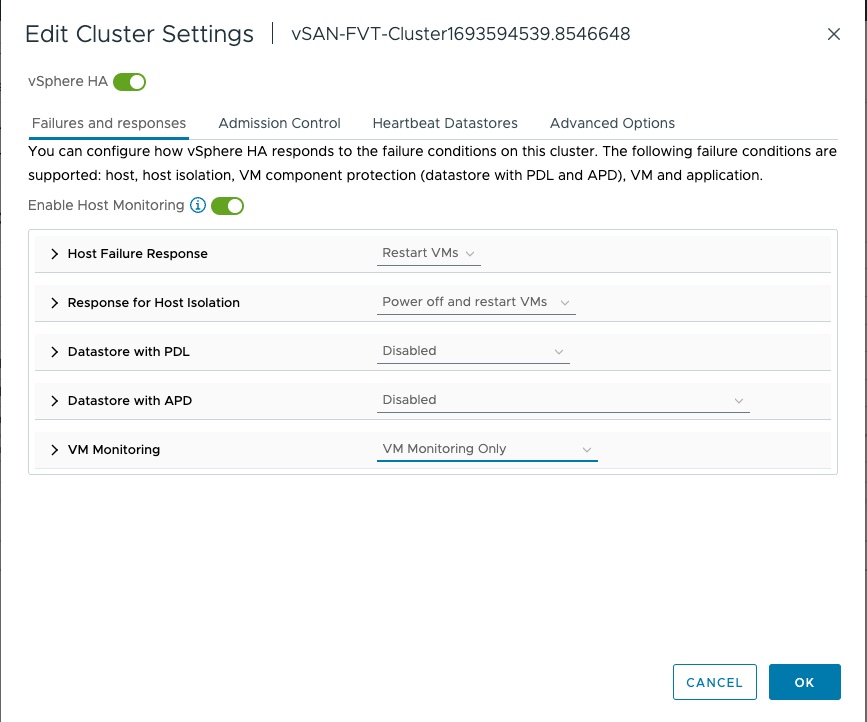
- Turn on vSphere HA.
Make sure to set up Host Monitoring.
- Enable host monitoring and configure host failure response, response for host isolation, and VM monitoring.
Note: VMware recommends you to disable VM Component Protection (VMCP) when all Node VMs and Volumes are deployed on the vSAN Datastore.
- Disable Datastore with PDL.
- Disable Datastore with APD.
- Create a vSAN stretched cluster.
- Create a VM storage policy compliant with the vSAN stretched cluster requirements.
- Configure Site disaster tolerance.
Select Dual site mirroring to have data mirrored at both sites of the stretched cluster.
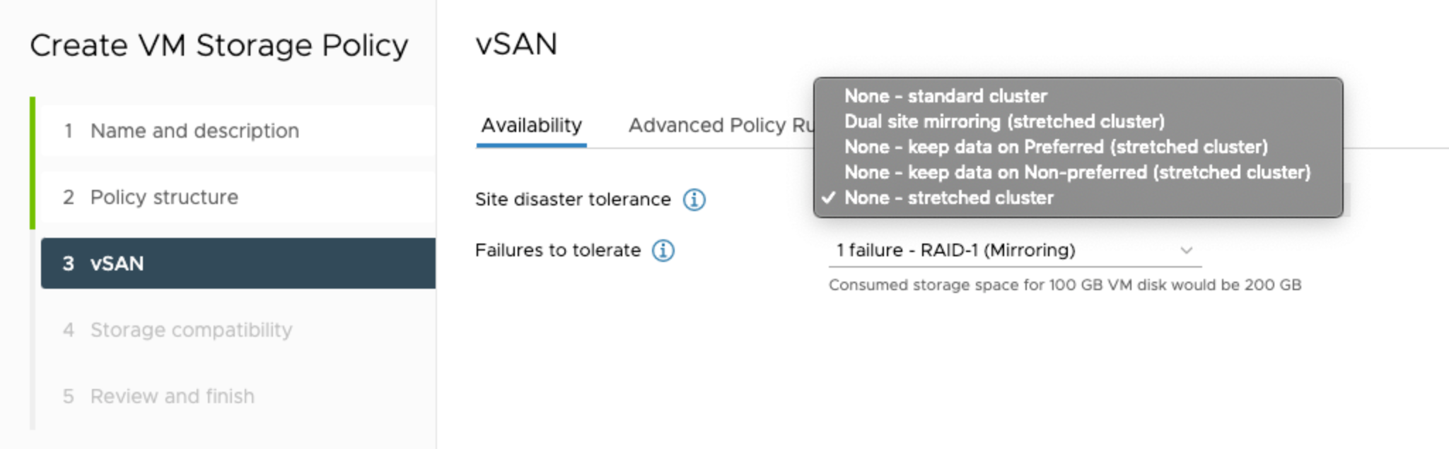
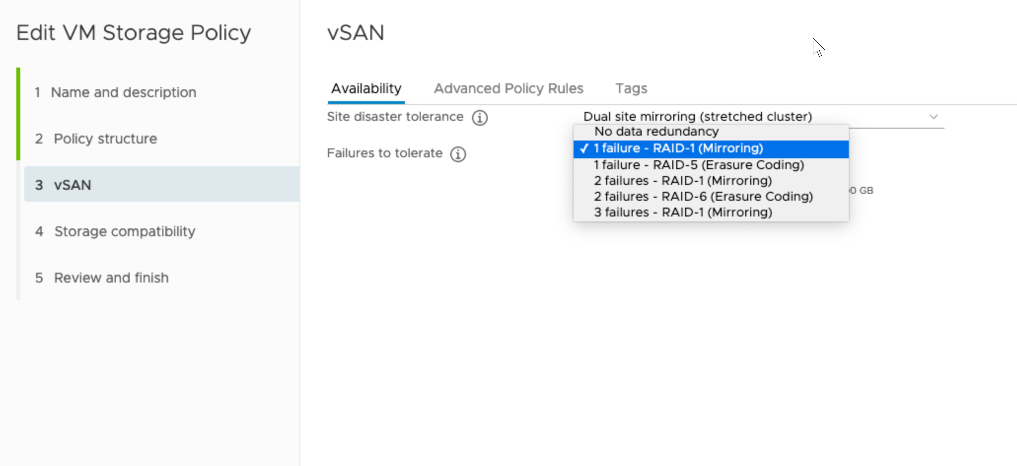
- Specify Failures to tolerate.
For the stretched cluster, the setting defines the number of disk or host failures a storage object can tolerate for each of the site. The number of required fault domains, or hosts within a site for the stretched cluster, in order to tolerate n failures is 2n + 1 for mirroring.
Raid-1 mirroring provides better performance. Raid-5 and Raid-6 achieve failure tolerance using parity blocks, which provides better space efficiency. These options are available only on all-flash clusters.
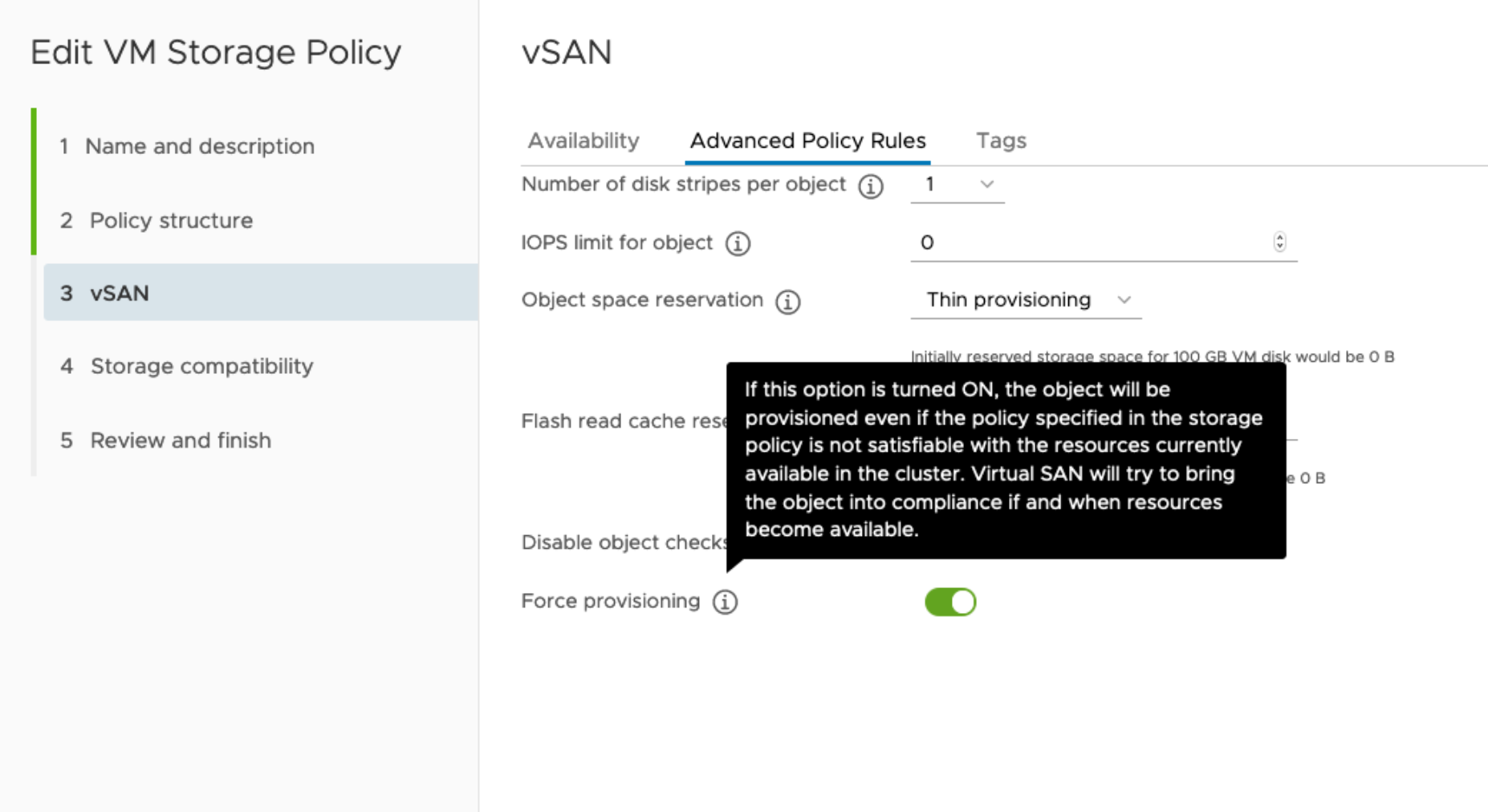
- Enable Force provisioning.
- Configure Site disaster tolerance.
- Create VM-Host affinity rules to place Kubernetes nodes on specific primary or secondary site, such as Site-A.
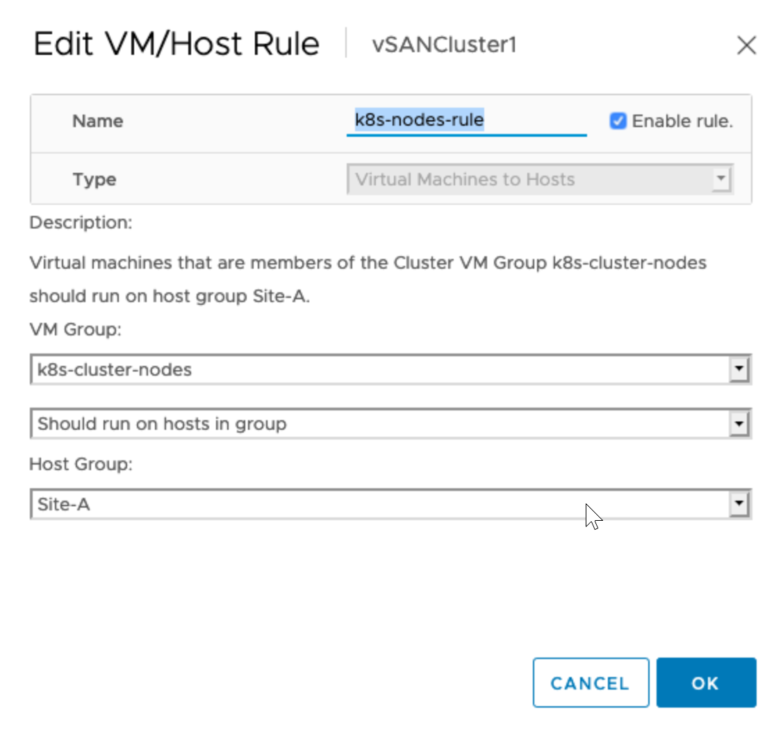 For information about affinity rules, see Create a VM-Host Affinity Rule in the vSphere Resource Management documentation.
What to do next
Deployment 1
In this deployment, the control plane and worker nodes are placed on the primary site, but flexible enough to failover on another site, if the primary site fails. You deploy HA Proxy on the primary site. This is also known as an Active-Passive deployment because only one site of the stretched vSAN cluster is used to deploy VMs.
If you plan to use file volumes (RWX volumes), it is recommended to configure the vSAN file service domain to place file servers on the active site (preferred site). This reduces the cross-site traffic latency and delivers better performance for applications using file volumes.
Requirements for Deployment 1
| Requirements | Parameters |
|---|---|
| Node Placement |
|
| Failure to Tolerate | At least FTT1 |
| DRS | Enabled |
| Site Disaster Tolerance | Dual Site Mirroring |
| Storage Policy Force Provisioning | Enabled |
| vSphere HA | Enabled |
Potential Failover Scenarios for Deployment 1
The following table describes potential failover scenarios that might occur when you use deployment model 1.
| Scenario | Description |
|---|---|
| Several ESXi hosts fail on the primary site. |
|
| The entire primary site and all hosts on the site fail. |
|
| Several hosts fail on the secondary site. | The failure does not affect the Kubernetes cluster because the entire cluster is at the primary site. |
| The entire secondary site and all hosts on the site fail. |
|
| Intersite network failure occurs. |
|
Deployment 2
With this model, place the control plane nodes on the primary site and worker nodes can be spread across the primary and secondary site. You deploy HA Proxy on the primary site.
Requirements for Deployment 2
| Requirements | Parameters |
|---|---|
| Node Placement |
|
| Failure to Tolerate | At least FTT1 |
| DRS | Enabled |
| Site Disaster Tolerance | Dual Site Mirroring |
| Storage Policy Force Provisioning | Enabled |
| vSphere HA | Enabled |
Potential Failover Scenarios for Deployment 2
The following table describes potential failover scenarios that might occur when you deploy a Kubernetes cluster using the Deployment 2 model.
| Scenario | Description |
|---|---|
| Several ESXi hosts fail on the primary site. |
|
| The entire primary site and all hosts on the site fail. |
|
| Several hosts fail on the secondary site. | Node VMs and pods running on the node VMs restart on another host. |
| The entire secondary site and all hosts on the site fail. |
|
| Intersite network failure occurs. |
|
Deployment 3
In this deployment model, you can place two control plane nodes on the primary site and one control plane node on the secondary site. Deploy HA Proxy on the primary site. Worker nodes can be on any site.
Requirements for Deployment 3
You can use this deployment model if you have equal resources at both the primary, or preferred, fault domain and the secondary, non-preferred, fault domain and you want to use hardware located at both fault domains. Since both fault domains have some workload running, in case of a complete site failure, this deployment model will help with faster recovery.
| Requirements | Parameters |
|---|---|
| Node Placement |
|
| Failure to Tolerate | At least FTT1 |
| DRS | Enabled |
| Site Disaster Tolerance | Dual Site Mirroring |
| Storage Policy Force Provisioning | Enabled |
| vSphere HA | Enabled |
Potential Failover Scenarios for Deployment 3
The following table describes potential failover scenarios that might occur when you use the Deployment 3 model.
| Scenario | Description |
|---|---|
| Several ESXi hosts fail on the primary site. |
|
| The entire primary site and all hosts on the site fail. |
|
| Several hosts fail on the secondary site. |
|
| The entire secondary site and all hosts on the site fail. |
|
| Intersite network failure occurs. |
|
Upgrade Kubernetes and Persistent Volumes on vSAN Stretched Clusters
If you already have Kubernetes deployments on a vSAN datastore, you can upgrade your deployments after enabling vSAN stretched clusters on the datastore.
