


You can configure a two-port LACP port channel on a switch and a two-uplink Link Aggregation Group on a vSphere distributed switch.
In this example, use 10Gb networking with two physical uplinks per server.
Configure the Network Switch
Configure the vSphere distributed switch with the following settings.
-
Identify the ports in question where the vSAN host will connect.
-
Create a port channel.
-
If using VLANs, then trunk the correct VLAN to the port channel.
-
Configure the desired distribution or load-balancing options (hash).
-
Setting LACP mode to active/dynamic.
-
Verify MTU configuration.
Configure vSphere
Configure the vSphere network with the following settings.
-
Configure vDS with the correct MTU.
-
Add hosts to vDS.
-
Create a LAG with the correct number of uplinks and matching attributes to port channel.
-
Assign physical uplinks to the LAG.
-
Create a distributed port group for vSAN traffic and assign correct VLAN.
-
Configure VMkernel ports for vSAN with correct MTU.
Set Up the Physical Switch
Configure the physical switch with the following settings. For guidance about how to set up this configuration on Dell servers, refer to: http://www.dell.com/Support/Article/us/en/19/HOW10364.
Configure a two uplink LAG:
-
Use switch ports 36 and 18.
-
This configuration uses VLAN trunking, so port channel is in VLAN trunk mode, with the appropriate VLANs trunked.
-
Use the following method for load-balancing or load distribution: Source and destination IP addresses, TCP/UDP port and VLAN
-
Verify that the LACP mode is Active (Dynamic).
Use the following commands to configure an individual port channel on a Dell switch:
-
Create a port-channel.
#interface port-channel 1
-
Set port-channel to VLAN trunk mode.
#switchport mode trunk
-
Allow VLAN access.
#switchport trunk allowed vlan 3262
-
Configure the load balancing option.
#hashing-mode 6
-
Assign the correct ports to the port-channel and set the mode to Active.
-
Verify that the port channel is configured correctly.
#show interfaces port-channel 1Channel Ports Ch-Type Hash Type Min-links Local Prf------- ----------------------------- -------- --------- --------- ---------Po1 Active:Te1/0/36, Te1/0/18Dynamic6 1 DisabledHash Algorithm Type1 - Source MAC, VLAN, EtherType, source module and port Id2 - Destination MAC, VLAN, EtherType, source module and port Id3 - Source IP and source TCP/UDP port4 - Destination IP and destination TCP/UDP port5 - Source/Destination MAC, VLAN, EtherType, source MODID/port6 - Source/Destination IP and source/destination TCP/UDP port7 - Enhanced hashing mode
#interface range Te1/0/36, Te1/0/18
#channel-group 1 mode active
Full configuration:
#interface port-channel 1
#switchport mode trunk
#switchport trunk allowed vlan 3262
#hashing-mode 6
#exit
#interface range Te1/0/36,Te1/018
#channel-group 1 mode active
#show interfaces port-channel 1
Set Up vSphere Distributed Switch
Before you begin, make sure that the vDS is upgraded to a version that supports LACP. To verify, right click the vDS, and check if the Upgrade option is available. You might have to upgrade the vDS to a version that supports LACP.
Create LAG on vDS
To create a LAG on a distributed switch, select the vDS, click the Configure tab, and select LACP. Add a new LAG.
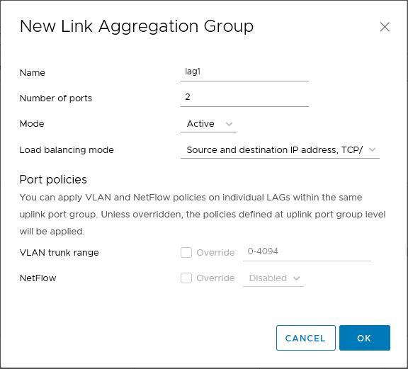
Configure the LAG with the following properties:
-
LAG name: lag1
-
Number of ports: 2 (to match port channel on switch)
-
Mode: Active, to match the physical switch.
-
Load balancing mode: Source and destination IP addresses, TCP/UDP port and VLAN
Add Physical Uplinks to LAG
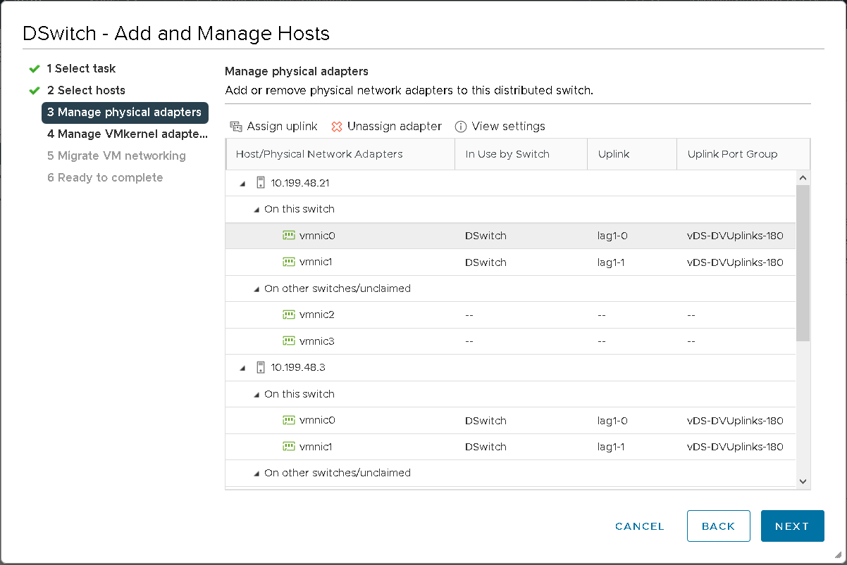
vSAN hosts have been added to the vDS. Assign the individual vmnics to the appropriate LAG ports.
-
Right click the vDS, and select Add and Manage Hosts…
-
Select Manage Host Networking, and add your attached hosts.
-
On Manage Physical Adapters, select the appropriate adapters and assign them to the LAG port.
- Migrate vmnic0 from Uplink 1 position to port 0 on LAG1.
Repeat the procedure for vmnic1 to the second LAG port position, lag1-1.
Configure Distributed Port Group Teaming and Failover Policy
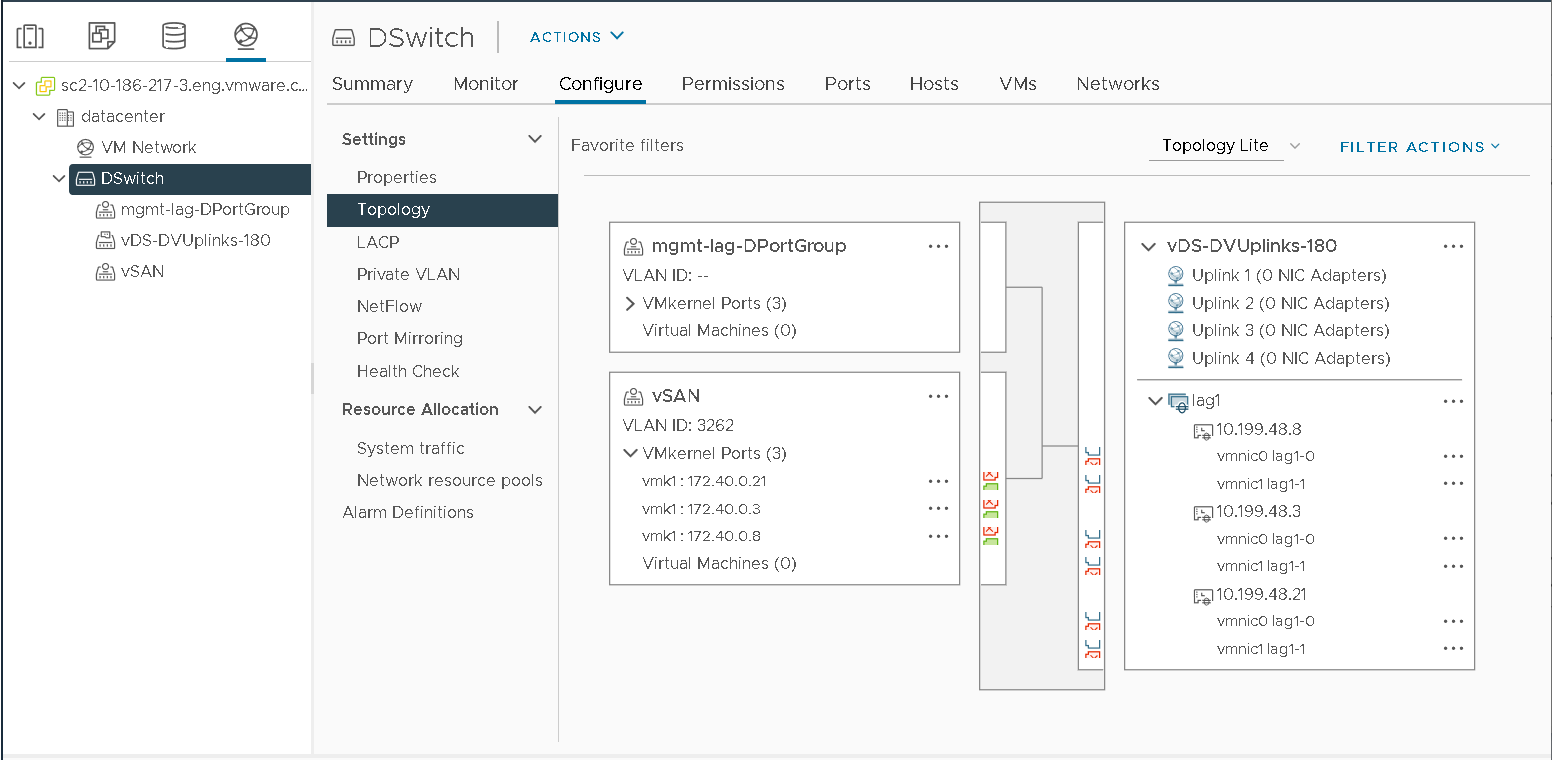
Assign the LAG group as an Active uplink on distributed port group teaming and failover policy. Select or create the designated distributed port group for vSAN traffic. This configuration uses a vSAN port group called vSAN with VLAN ID 3262 tagged. Edit the port group, and configure Teaming and Failover Policy to reflect the new LAG configuration.
Ensure the LAG group lag1 is in the active uplinks position, and ensure the remaining uplinks are in the Unused position.
Create the VMkernel Interfaces
The final step is to create the VMkernel interfaces to use the new distributed port group, ensuring that they are tagged for vSAN traffic. Observe that each vSAN vmknic can communicate over vmnic0 and vmnic1 on a LAG group to provide load balancing and failover.
Configure Load Balancing
From a load balancing perspective, there is not a consistent balance of traffic across all hosts on all vmnics in this LAG setup, but there is more consistency compared to Route based on physical NIC load used in Configuration 1 and the air-gapped/multiple vmknics method used in Configuration 2.
The individual hosts’ vSphere performance graph shows improved load balancing.
Network Uplink Redundancy Lost
When vmnic1 is not enabled on a given vSAN host, a Network Redundancy alarm is triggered.
No vSAN health alarms are triggered, and the impact to Guest I/O is minimal compared to the air-gapped, multi-vmknics configuration. This configuration does not have to stop any TCP sessions with LACP configured.
Recovery and Failback
In a failback scenario, the behavior differs between Load Based Teaming, multiple vmknics, and LACP in a vSAN environment. After vmnic1 recovers, traffic is automatically balanced across both active uplinks. This behavior can be advantageous for vSAN traffic.
Failback Set to Yes or No?
A LAG load-balancing policy overrides the Teaming and Failover policy for vSphere distributed port groups. Also consider the guidance on Failback value. Lab tests show no discernable behavior differences between Failback set to yes or no with LACP. LAG settings takes priority over the port-group settings.
