vSAN supports several single-site deployment types.
Layer-2, Single Site, Single Rack
This network topology is responsible for forwarding packets through intermediate Layer 2 devices such as hosts, bridges, or switches.
The Layer 2 network topology offers the simplest implementation and management of vSAN. VMware recommends the use and configuration of IGMP Snooping to avoid sending unnecessary multicast traffic on the network. In this first example, we are looking at a single site, and perhaps even a single rack of servers using vSAN 6.5 or earlier. This version uses multicast, so enable IGMP Snooping. Since everything is on the same L2, you need not configure routing for multicast traffic.
Layer 2 implementations are simplified even further with vSAN 6.6 and later, which introduces unicast support. IGMP Snooping is not required.

Layer 2, Single Site, Multiple Racks
This network topology works with the Layer 2 implementation where there are multiple racks, and multiple top-of-rack switches, or TORs, connected to a core switch.
In the following figures, the blue dotted line between the TORs shows that the vSAN network is available and accessible to all the hosts in the vSAN cluster. However, the hosts in the different racks communicate to each other over Layer 3, which implies using PIM to route multicast traffic between the hosts. The TORs are not physically connected to each other.
VMware recommends that all TORs are configured for IGMP Snooping, to prevent unnecessary multicast traffic on the network. As there is no routing of the traffic, there is no need to configure PIM to route the multicast traffic.
This implementation is easier in vSAN 6.6 and later, because vSAN traffic is unicast. With unicast traffic, there is no need to configure IGMP Snooping on the switches.

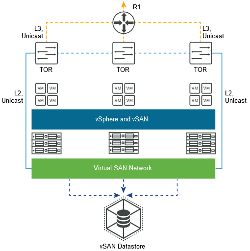
Layer 3, Single Site, Multiple Racks
This network topology works for vSAN deployments where Layer 3 is used to route vSAN traffic.
This simple Layer 3 network topology uses multiple racks in the same data center, each with its own TOR switch. Route the vSAN network between the different racks over L3, to allow all the hosts in the vSAN cluster to communicate. Place the vSAN VMkernel ports on different subnets or VLANs, and use a separate subnet or VLAN for each rack.
This network topology routes packets through intermediate Layer 3 capable devices, such as routers and Layer 3 capable switches. Whenever hosts are deployed across different Layer 3 network segments, the result is a routed network topology.
With vSAN 6.5 and earlier, VMware recommends the use and configuration of IGMP Snooping, because these deployments require multicast. Configure PIM on the physical switches to facilitate the routing of the multicast traffic.
vSAN 6.6 and later simplifies this topology. As there is no multicast traffic, there is no need to configure IGMP Snooping. You do not need to configure PIM to route multicast traffic.
Here is an overview of an example vSAN 6.6 deployment over L3. There is no requirement for IGMP Snooping or PIM, because there is no multicast traffic.