vSphere Standard Switch settings control switch-wide defaults for ports, which can be overridden by port group settings for each standard switch. Learn how to edit standard switch properties, such as the uplink configuration and the number of available ports.
Number of Ports on ESXi Hosts
To ensure efficient use of host resources on ESXi hosts, the ports of virtual switches are dynamically scaled up and down. A switch on such a host can expand up to the maximum number of ports supported on the host. The port limit is determined based on the maximum number of virtual machines that the host can handle.
Change the Size of the MTU on a vSphere Standard Switch
Learn how to change the size of the maximum transmission unit (MTU) on a vSphere Standard Switch to improve the networking efficiency by increasing the amount of payload data transmitted with a single packet, that is, enabling jumbo frames.
Procedure
Change the Speed of a Physical Adapter
Learn how to change the connection speed and duplex of a physical adapter to transfer data in compliance with the traffic rate.
If the physical adapter supports SR-IOV, you can enable it and configure the number of virtual functions to use for virtual machine networking.
Procedure
Assign Physical Adapters to a vSphere Standard Switch
Learn how to assign a physical adapter to a standard switch to provide connectivity to virtual machines and VMkernel adapters on the host. You can form a team of NICs to distribute traffic load and to configure failover.
Procedure
- In the vSphere Client, navigate to the host.
- On the Configure tab, expand Networking and select Virtual Switches.
- Select the standard switch you want to add a physical adapter to.
- Click Manage Physical Adapters.
- Add one or more available physical network adapters to the switch.
- Click Add adapters, select one or more network adapters from the list and click OK.
The selected adapters appear in the failover group list under the Assigned Adapters list.
- (Optional) Use the up and down arrows to change the position of an adapter in the failover groups.
The failover group determines the role of the adapter for exchanging data with the external network, that is, active, standby or unused. By default, the adapters are added as active to the standard switch.
- Click Add adapters, select one or more network adapters from the list and click OK.
- Click OK to apply the physical adapter configuration.
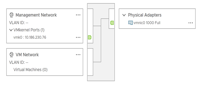
Topology of a vSphere Standard Switch
View the structure and components of a vSphere Standard Switch by using its topology diagram.
The topology diagram of a standard switch provides a visual representation of the adapters and port groups connected to the switch.
From the diagram you can edit the settings of a selected port group and of a selected adapter.
Procedure
- In the vSphere Client, navigate to the host.
- On the Configure tab, expand Networking and select Virtual Switches.
- Select the standard switch from the list.
Results
Example: Diagram of a Standard Switch That Connects the VMkernel and Virtual Machines to the Network
In your virtual environment, a vSphere Standard Switch handles VMkernel adapters for vSphere vMotion and for the management network, and virtual machines grouped. You can use the central topology diagram to examine whether a virtual machine or VMkernel adapter is connected to the external network and to identify the physical adapter that carries the data.