


The topology diagrams of a vSphere Distributed Switch in the vSphere Client show the structure of virtual machine adapters, VMkernel adapters, and physical adapters in the switch.
You can examine the components, arranged in port groups, whose traffic is handled by the switch, and the connections between them. The diagram displays information about the physical adapter that connects the virtual adapters to the external network.
You can view the components that are running on the entire distributed switch and on each host participating in it.
Watch the video about the operations that you can perform from the topology diagram of vSphere Distributed Switch.
Central Topology Diagram
You can use the central topology diagram of the switch to locate and edit the settings for distributed port groups and uplink groups associated with multiple hosts. You can initiate migration of virtual machine adapters from a port group to a destination on the same or different switch. You can also reorganize the hosts and their networking on the switch by using the Add and Manage Hosts wizard.
Topology Diagram of a Host Proxy Switch
The topology diagram of a host proxy switch shows the adapters attached to the switch ports on the host. You can edit the settings of the VMkernel and physical adapters.
Topology Diagram of a Network Offloads Switch
The topology diagram of a network offloads switch shows the adapters attached to the switch ports on the host. You can edit the settings of the VMkernel and physical adapters.
Diagram Filters
You can use diagram filters to limit the information displayed in topology diagrams. The default filter limits the topology diagram to display 32 port groups, 32 hosts, and 1024 virtual machines.
You can change the scope of the diagram by using no filters or by applying custom filters. By using a custom filter, you can view information only about a set of virtual machines, a set of port groups on certain hosts, or a port. You can create filters from the central topology diagram of the distributed switch.
View the Topology of a vSphere Distributed Switch
Examine the organization of components that are connected to the distributed switch across the hosts in a vCenter Server.
Procedure
- Navigate to the vSphere distributed switch in the vSphere Client.
- On the Configure tab, expand Settings and select Topology.
Results
By default the diagram shows up to 32 distributed port groups, 32 hosts, and 1024 virtual machines.
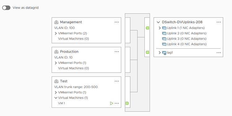
Example: Diagram of a Distributed Switch That Connects the VMkernel and Virtual Machines to the Network
In your virtual environment, a vSphere Distributed Switch handles VMkernel adapters for vSphere vMotion and for the management network, and virtual machines grouped. You can use the central topology diagram to examine whether a virtual machine or VMkernel adapter is connected to the external network and to identify the physical adapter that carries the data.
What to do next
You can perform the following common tasks in the topology of the distributed switch:
- Use filters to view the networking components only for selected port groups on certain hosts, for selected virtual machines, or for a port.
- Locate, configure and migrate virtual machine networking components across host and port groups by using the Migrate Virtual Machine Networking wizard.
- Detect the virtual machine adapters that have no network assigned and move them to the selected port group by using the Migrate Virtual Machine Networking wizard.
- Handle networking components on multiple hosts by using the Add and Manage Hosts wizard.
- View the physical NIC or NIC team that carries the traffic related to a selected virtual machine adapter or VMkernel adapter.
In this way you can also view the host on which a selected VMkernel adapter resides. Select the adapter, trace the route to the associated physical NIC, and view the IP address or domain name next to the NIC.
- Determine the VLAN mode and ID for a port group. For information about VLAN modes, see VLAN Configuration.
View the Topology of a Host Proxy Switch
Examine and reorganize the networking of the VMkernel and virtual machines that the vSphere Distributed Switch handles on a host.
Procedure
- In the vSphere Client, navigate to the host.
- On the Configure tab, expand Networking and select Virtual Switches.
- Select the distributed switch from the list.
Results
View the Topology of Network Offloads Switch
Examine the organization of the distributed switch with network offloads.
Procedure
- In the vSphere Client, navigate to the host.
- On the Configure tab, expand Networking and select Virtual Switches.
- The
 icon indicates that network offloads is supported for this distributed switch.
