


An HCX Service Mesh provides the HCX services configuration for a Site Pair. This section describes the procedure for creating a Service Mesh for a vSphere-based HCX Site Pair.
Adding a Service Mesh initiates the deployment of HCX Interconnect virtual appliances on both of the sites. A Service Mesh is always created at the source site.
Prerequisites
Creating a Service Mesh requires:
A connected Site Pair.
A valid Compute Profile at the HCX source and HCX destination site.
Virtual Switches (for Network Extension) and Network Profiles selected in each Compute Profile must span across all hosts in every selected deployment cluster. If these objects do not span all hosts, it is possible that the appliances will be deployed in a host missing the needed networks. In this case, the Service Mesh deployment can fail or services may not function properly.
Procedure
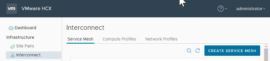
- Click Create Service Mesh:
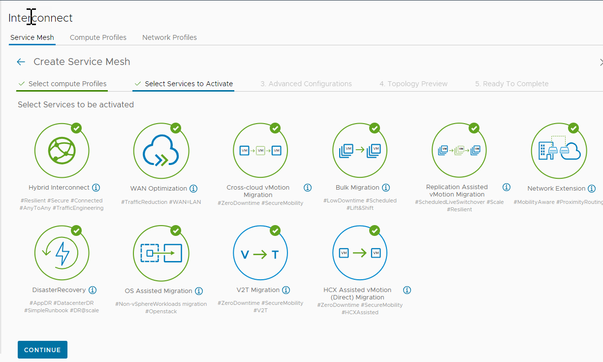
- Select the services to be activated, and click Continue.
The HCX services available for activation are based on your selections in the source and remote site Compute Profiles, and based on the service entitlements for each site. In cases where the source and remote sites have been activated with different entitlements, the Service Mesh can inherit entitlements from either site. For more information, see Understanding Service Inheritance.
- (Optional) Configure HCX Traffic Engineering features:
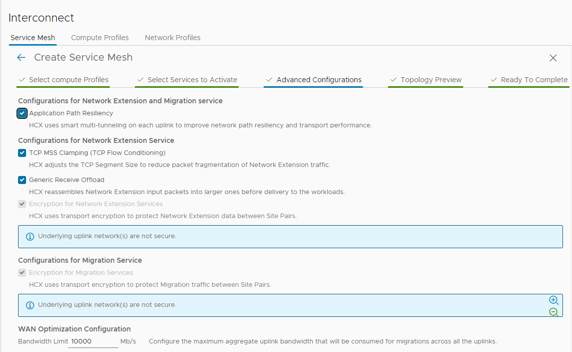
- To create multiple transport tunnels for directing the HCX traffic to a destination site, check Application Path Resiliency.
Enabling Application Path Resiliency (APR) creates up to eight transport tunnels between each Interconnet and Network Extension appliance uplink interface IP address pair between sites. If a few tunnels fail, there is no impact in the data traffic as only one transport tunnel out of eight is used always to provide secure data transfer across the Wide Area Network (WAN) or Internet connection.
Application Path Resiliency forwards traffic over one tunnel at a time and does not load balance across multiple paths.
Note:To view the available tunnels after completing the Service Mesh configuration, navigate to and expand the HCX-WAN-IX appliance.
Important: For additional dynamic tunnel requirement, the source Interconnect (IX) and Network Extension (NE) appliances uses a random source UDP port in the 4500 – 4628 range and target UDP port as 4500 to create a different flow for each subsequent tunnel. The reverse tunnel originated by target IX/NE appliances have source port as UDP 4500 and destination ports from same random ports used by source appliances for the forward direction in the range 4500 – 4628.Ensure the firewall settings on either side allow for that connectivity.
- To dynamically manage the TCP segment size and optimize the transport performance for the HCX Network Extension service traffic, check TCP MSS Clamping.
This option is available only after activating the HCX Network Extension service.
- To reassemble Network Extension input packets into larger ones before delivery to the workloads, check Generic Receive Offload.
- To activate or deactivate transport encryption for Network Extension data between site pair, check or uncheck Encryption for Network Extension Services.
By default this option is checked. Deactivating, or unchecking, this box is available only on Uplink networks that have been verifed as secure in the Network Profile configuration.
- To activate or deactivate transport encryption migration traffic between Site Pairs, check or uncheck Encryption for Migration Services.
By default this option is checked. Deactivating, or unchecking, this box is available only on Uplink networks that have been verifed as secure in the Network Profile configuration.
- To manage the bandwidth consumed for migrations across all uplink networks, use the up and down arrows to change the bandwidth setting.
This option is available only after activating the HCX WAN Optimization service.
Note:It is a best practice to retain the default setting of 10000 Mb/S.
- To create multiple transport tunnels for directing the HCX traffic to a destination site, check Application Path Resiliency.
What to do next
After the Service Mesh configuration is complete, verify the underlay network performance for each Uplink Network. The underlay network performance must meet the minimum requirements for HCX services. See Understanding HCX Transport Analytics.
If you are migrating guest workloads using OS Assisted Migration, download and install the Sentinel software on each guest workload. See Sentinel Management.
If it is necessary to edit an existing Service Mesh, such as activating or deactivating services and overriding uplinks, select . The editing workflow includes a preview screen, listing the changes and describing the impact of those changes on related services prior to finishing the procedure. You can select to complete or cancel the update.
