


Source NAT can be used with either of the high availability (HA) modes, such as elastic HA or legacy HA. The configuration requirements differ depending on whether the SE and back end servers are in the same subnet (connected at Layer 2) or in different subnets (connected at Layer 3).
SE-server Connection |
HA Type |
Requirements |
|---|---|---|
Layer 2 |
Elastic HA |
SNAT IPs: 1 per SE |
(Active/ Active) |
Floating IP: Not Required |
|
Legacy HA |
SNAT IPs: 1 per virtual service |
|
(Active/ Standby) |
Floating IP: Not Required |
|
Layer 3 |
Dynamic HA using BGP |
SNAT IPs: 1 per SE in SE group (to support scale out) |
(Active/ Active) |
Floating IP: Not Required |
|
Legacy HA |
SNAT IPs: 1 per virtual service |
|
(Active/ Standby) |
Floating IP: Required |
In Layer 3 HA, the upstream router is used to provide equal-cost multipath (Legacy HA for NSX Advanced Load Balancer Service Engines) load balancing across the virtual service’s SEs.
For Layer 3 HA, the configuration might be required on the router between the SEs and the back end servers to enable return traffic from the server to reach the SEs.
In Layer 2 HA, scale-out is not possible.
Virtual services can have SNAT enabled when associated with a Service Engine Group and VRF that have a network service with IP routing enabled. However, on any given virtual service preserve_client_ip will take precedence over SNAT IP.
Layer 2: Cluster HA (A/A)
In Layer 2 cluster HA, one SNAT IP is required per SE at the virtual service configuration level. When an SE initiates the connection to the back end server, the SNAT IP corresponding to that SE will be used for the connection.
If the default Layer-2 forwarding option is used, the connections from clients can always go to the primary SE and then get distributed using Layer 2 forwarding. Here is an example of a typical Layer 2 cluster HA topology.
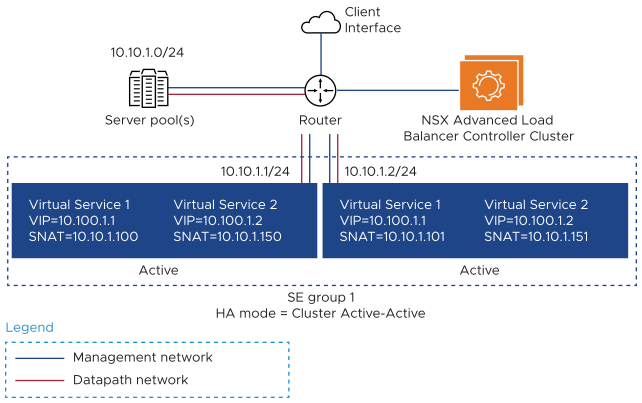
In this topology, two virtual services are configured. Each of the virtual services is provisioned with a distinct SNAT IP. Since cluster HA is selected, each virtual service will need to be provisioned with as many SNAT IPs as the number of SEs in the SE group. The Controller will automatically distribute the SNAT IPs to the individual SEs on which the virtual services are enabled.
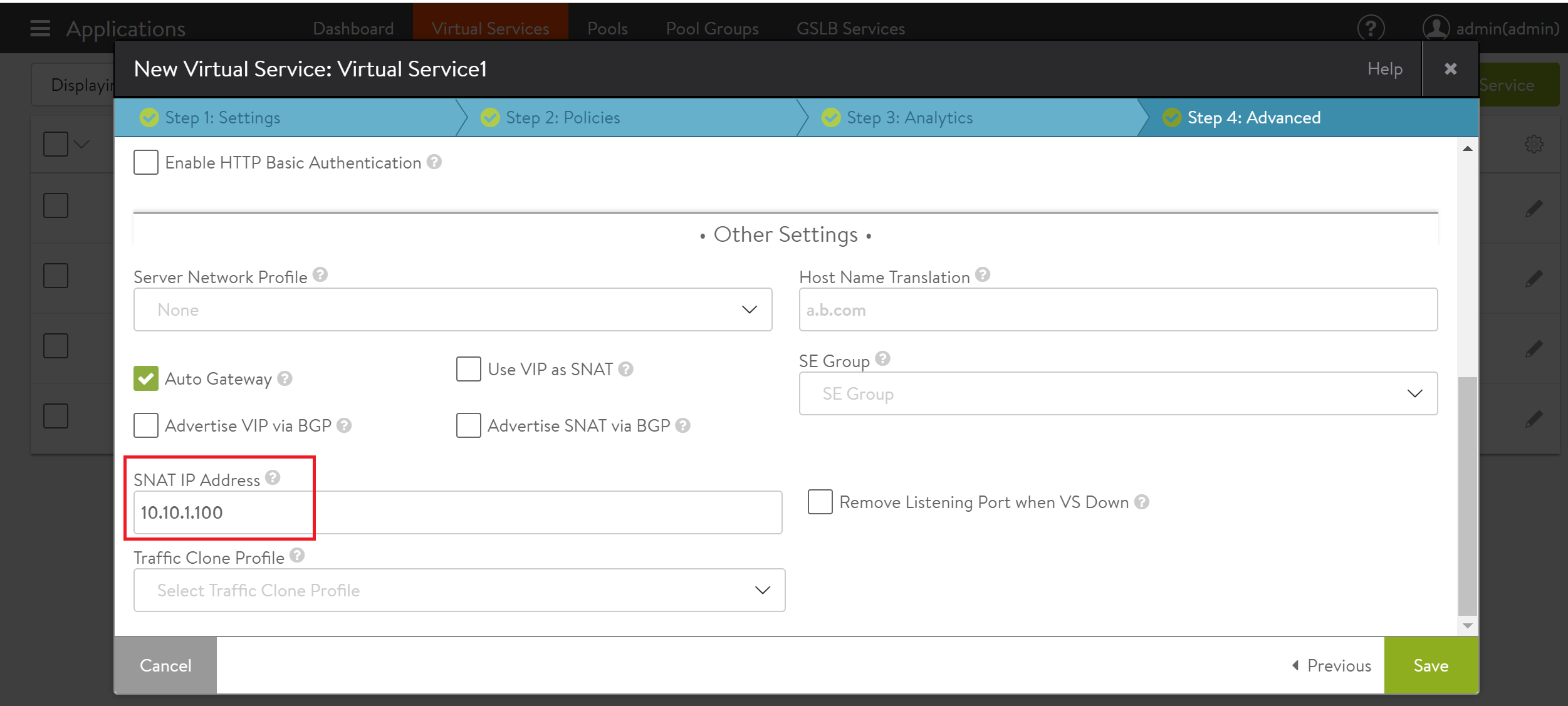
Here is the SNAT configuration in the web interface for Virtual Service 1 with IPv4 addresses in the example topology.

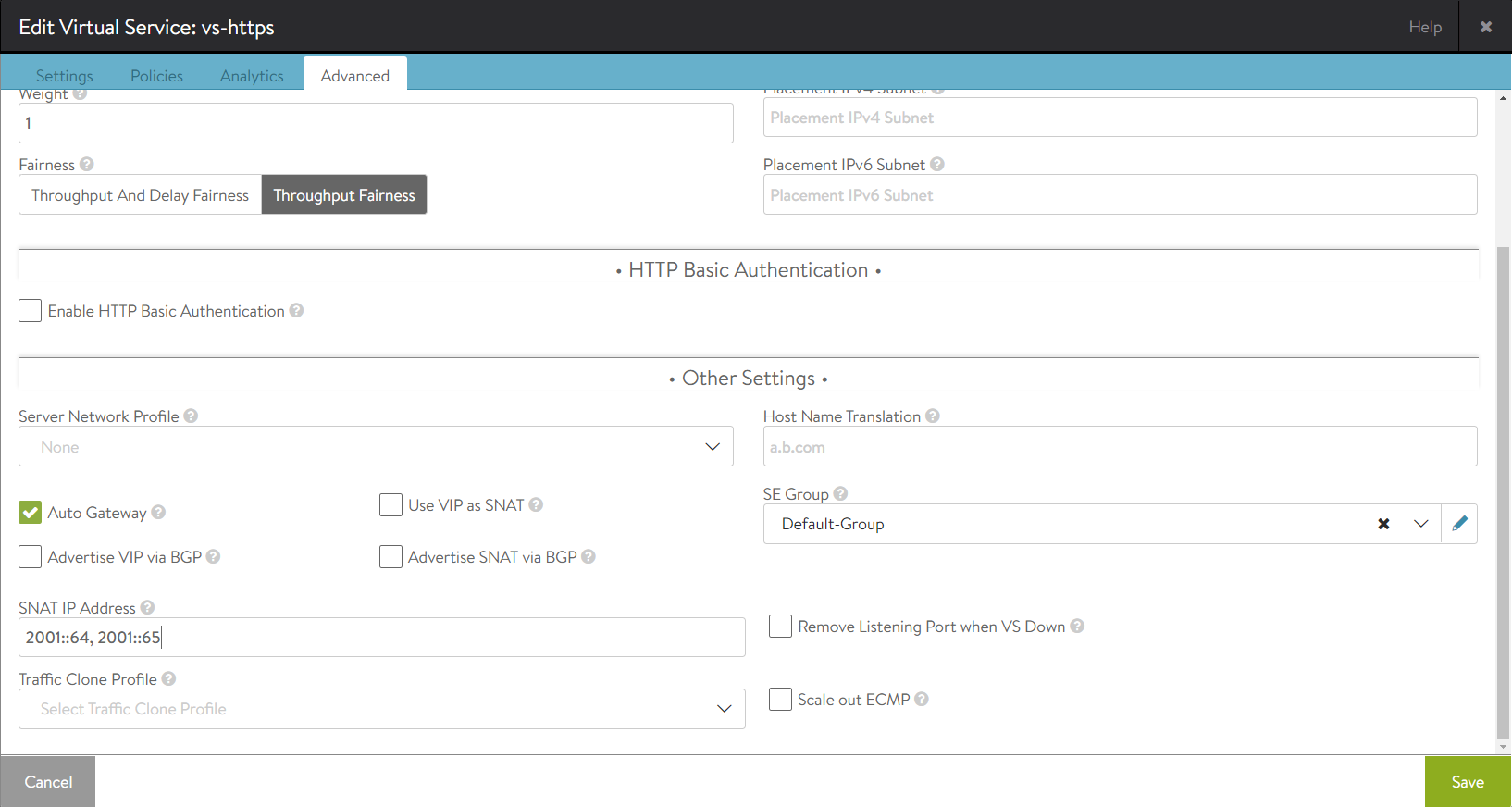
Here is the SNAT configuration in the web interface for Virtual Service 1 with IPv6 addresses in the example topology.
Layer 2: Legacy HA (A/S)
Legacy HA mode typically is used when migrating from appliance-based load balancing deployments, which support only 1:1 active-standby HA mode. In this case, only a single SNAT IP per virtual service is necessary since the standby SE does not carry any traffic. Here is an example of a typical Layer 2 legacy HA topology.
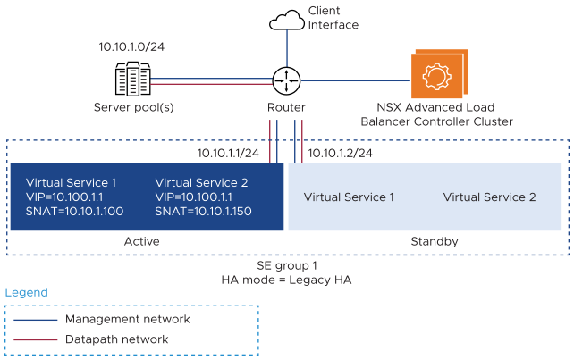
If there is a failover, the newly active SE will take over the traffic and ownership of the SNAT IP from the failed SE. Health monitoring is performed only by the active SE.
Here is the SNAT configuration in the web interface for Virtual Service 1 in the example topology.
Layer 3: Elastic HA (A/A)
In Layer 3 dynamic HA, the SNAT IP is advertised dynamically through BGP. BGP support is enabled in the virtual service configuration. Using BGP enables an active/ active scale-out topology when the SNAT IP is not part of the SE interface’s subnet.
When SNAT is enabled, NSX Advanced Load Balancer users will need to provide as many SNAT IPs as the width of the scale-out desired. For instance, to support a maximum of four SEs, four unique SNAT IPs are required in the virtual service configuration. If fewer SNAT IPs are configured than the maximum scale outsize, scale-out is limited to one SE per configured SNAT IP.
Here is an example topology with SNAT enabled in scale-out HA mode with BGP enabled.
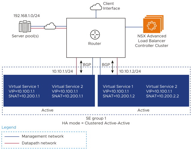
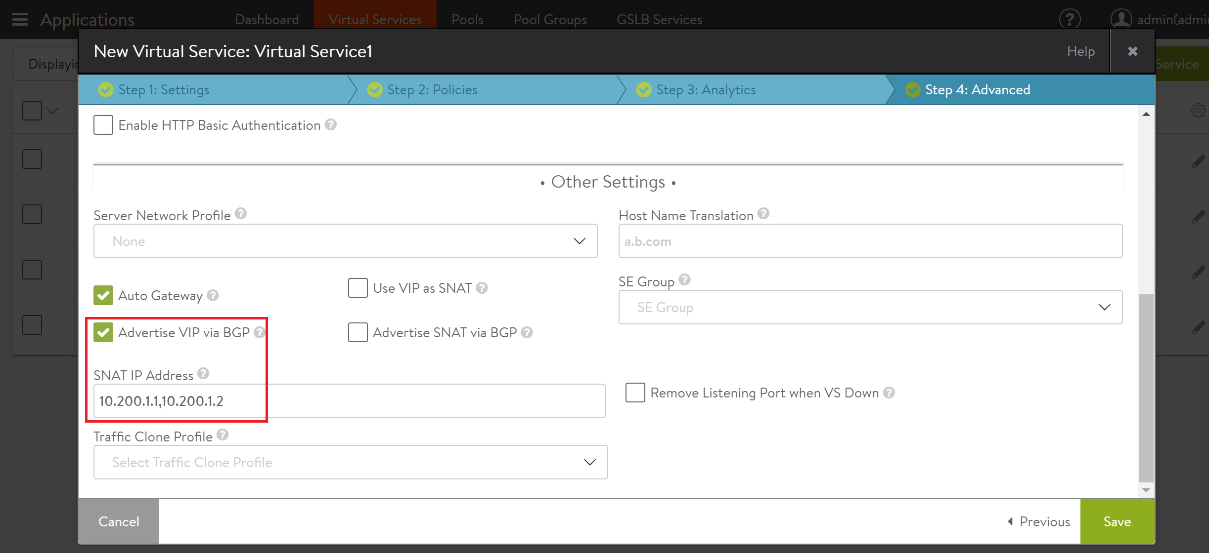
Here is the SNAT configuration in the web interface for Virtual Service 1 in the example topology.
For more information on enabling BGP to advertise SNAT IP addresses, see BGP Support for Scaling Virtual Services.
Layer 3: Legacy HA (A/S)
This mode requires only a single SNAT IP per virtual service since scaling out is not possible. The active SE carries all the traffic and owns the SNAT IP, whereas the standby SE remains idle. In case of a failover, the standby SE takes over the traffic and ownership of the SNAT IP.
A floating interface IP needs to be provisioned to provide adjacency to the upstream router for the SNAT IP.
For more information, see Legacy HA for NSX Advanced Load Balancer Service Engines.
Using the CLI
The following commands add SNAT IP address 10.200.1.1 and 2001::10 to Virtual Service 1:
: > configure virtualservice Virtual Service 1
...

: snat_ip 10.200.1.1
: snat_ip 2001::10
: save
