


One of the ways NSX Advanced Load Balancer adds load balancing capacity for a virtual service is to place the virtual service on additional Service Engines (SEs).
For instance, capacity can be added for a virtual service when needed by scaling out the virtual service to additional SEs within the SE group, then removing (scaling in) the additional SEs when no longer needed. In this case, the primary SE for the virtual service coordinates the distribution of the virtual service traffic among the other SEs, while also continuing to process some of the virtual service’s traffic.
An alternative method for scaling a virtual service is to use a Border Gateway Protocol (BGP) feature, route health injection (RHI), with a layer 3 routing feature, equal-cost multi-path (ECMP). Using Route Health Injection (RHI) with ECMP for virtual service scaling avoids the managerial overhead placed upon the primary SE to coordinate the scaled out traffic among the SEs.
BGP is supported in legacy (active/ standby) and elastic (active/ active and N+M) high availability modes.
If a virtual service is marked down by its health monitor or for any other reason, the NSX Advanced Load Balancer SE withdraws the route advertisement to its virtual IP (VIP) and restores the same only when the virtual service is marked up again.
Notes on Limits
- Service Engine Count:
-
By default, NSX Advanced Load Balancer supports a maximum of four SEs per virtual service, and this can be increased to a maximum of 64 SEs. Each SE uses RHI to advertise a
/32host route to the virtual service’s VIP address and can accept the traffic. The upstream router uses ECMP to select a path to one of the SEs.The limit on SE count is imposed by the ECMP support on the upstream router. If the router supports up to 64 equal-cost routes, then a virtual service enabled for RHI can be supported on up to 64 SEs. Similarly, if the router supports a lesser number of paths, then the virtual service count enabled for RHI will be lower.
- Subnets and Peers:
-
NSX Advanced Load Balancer supports four distinct subnets with any number of peers in those four subnets. Consequently, a VIP can be advertised on more than four peers if those peers belong to four or fewer subnets. To illustrate:
A VIP can be advertised to 8 peers, all belonging to a single subnet.
A VIP can be advertised to 4 pairs of peers (once again, 8 peers), with each pair belonging to a separate subnet.
Supported Ecosystem
BGP-based scaling is supported in the following:
VMware
Linux server (bare-metal) cloud
OpenShift and Kubernetes
Note:Peering with OpenStack routers is not supported. However, peering with an external router is possible.
BGP-based Scaling
NSX Advanced Load Balancer supports the use of the following routing features to dynamically perform virtual service load balancing and scaling:
- Route health injection (RHI):
-
RHI allows traffic to reach a VIP that is not in the same subnet as its SE. The NSX Advanced Load Balancer Service Engine (SE) where a virtual service is located advertises a host route to the VIP for that virtual service, with the SE’s IP address as the next-hop router address. Based on this update, the BGP peer connected to the NSX Advanced Load Balancer SE updates its route table to use the NSX Advanced Load Balancer SE as the next hop for reaching the VIP. The peer BGP router also advertises itself to its upstream BGP peers as a next hop for reaching the VIP.
- Equal cost multi-path (ECMP):
-
Higher bandwidth for the VIP is provided by load sharing its traffic across multiple physical links to the SE(s). If an NSX Advanced Load Balancer SE has multiple links to the BGP peer, the NSX Advanced Load Balancer SE advertises the VIP host route on each of those links. The BGP peer router sees multiple next-hop paths to the virtual service’s VIP and uses ECMP to balance traffic across the paths. If the virtual service is scaled out to multiple NSX Advanced Load Balancer SEs, each SE advertises the VIP, on each of its links to the peer BGP router.
When a virtual service enabled for BGP is placed on its NSX Advanced Load Balancer SE, that SE establishes a BGP peer session with each of its next-hop BGP peer routers. The NSX Advanced Load Balancer SE then performs RHI for the virtual service’s VIP by advertising a host route (/32 network mask) to the VIP. The NSX Advanced Load Balancer SE sends the advertisement as a BGP route update to each of its BGP peers. When a BGP peer receives this update from the NSX Advanced Load Balancer SE, the peer updates its route table with a route to the VIP that uses the SE as the next hop. Typically, the BGP peer also advertises the VIP route to its other BGP peers.
The BGP peer IP addresses and the local Autonomous System (AS) number and a few other settings are specified in a BGP profile on the NSX Advanced Load Balancer Controller. RHI support is disabled (default) or enabled within the individual virtual service’s configuration. If an NSX Advanced Load Balancer SE has more than one link to the same BGP peer, this also enables ECMP support for the VIP. The NSX Advanced Load Balancer SE advertises a separate host route to the VIP on each of the NSX Advanced Load Balancer SE interfaces with the BGP peer.
If the NSX Advanced Load Balancer SE fails, the BGP peers withdraw the routes that were advertised to them by the NSX Advanced Load Balancer SE.
BGP Profile Modifications
BGP peer changes are handled as follows:
If a new peer is added to the BGP profile, the virtual service IP is advertised to the new BGP peer router without needing to deactivate or enable the virtual service.
If a BGP peer is deleted from the BGP profile, any virtual service IPs that had been advertised to the BGP peer will be withdrawn.
When a BGP peer IP is updated, it is handled as an add/ delete of the BGP peer.
BGP Upstream Router Configuration
The BGP control plane can hog the CPU on the router in case of scale setups. Changes to CoPP policy are needed to have more BGP packets on the router, or this can lead to BGP packets getting dropped on the router when churn happens.
The ECMP route group or ECMP next-hop group on the router could exhaust if the unique SE BGP next-hops advertised for a different set of virtual service VIPs. When such exhaustion happens, the routers could fall back to a single SE next-hop causing traffic issues.
Sample Configuration
The following is the sample configuration on a Dell S4048 switch for adding 5k network entries and 20k paths:
w1g27-avi-s4048-1#show ip protocol-queue-mapping
 Protocol   Src-Port   Dst-Port   TcpFlag  Queue   EgPort     Rate (kbps)
 --------   --------   --------   -------  -----   ------     -----------
TCP (BGP)     any/179    179/any    _        Q9      _           10000
UDP (DHCP)    67/68      68/67      _        Q10     _           _
UDP (DHCP-R)  67         67         _        Q10     _           _
TCP (FTP)     any        21         _        Q6      _           _
ICMP          any        any        _        Q6      _           _
IGMP          any        any        _        Q11     _           _
TCP (MSDP)    any/639    639/any    _        Q11     _           _
UDP (NTP)     any        123        _        Q6      _           _
OSPF          any        any        _        Q9      _           _
PIM           any        any        _        Q11     _           _
UDP (RIP)     any        520        _        Q9      _           _
TCP (SSH)     any        22         _        Q6      _           _
TCP (TELNET)  any        23         _        Q6      _           _
VRRP          any        any        _        Q10     _           _
MCAST         any        any        _        Q2      _           _
w1g27-avi-s4048-1#show cpu-queue rate cp
 Service-Queue         Rate (PPS)      Burst (Packets)
 --------------        -----------      ----------
Q0                        600             512
Q1                        1000            50
Q2                        300             50
Q3                        1300            50
Q4                        2000            50
Q5                        400             50
Q6                        400             50
Q7                        400             50
Q8                        600             50
Q9                        30000           40000
Q10                       600             50
Q11                       300             50
SE-Router Link Types Supported with BGP
The following figure shows the types of links that are supported between NSX Advanced Load Balancer and BGP peer routers:
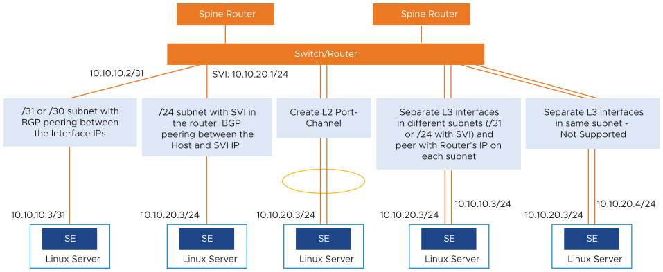
BGP is supported over the following types of links between the BGP peer and the NSX Advanced Load Balancer SEs:
Host route (
/30or/31mask length) to the VIP, with the NSX Advanced Load Balancer SE as the next hop.Network route (
/24mask length) subnet with Switched Virtual Interface (SVI) configured in the router.Layer 2 port-channel (separate physical links configured as a single logical link on the next-hop switch or router).
Multiple layer 3 interfaces, in separate subnets (
/31or/24with SVI). A separate BGP peer session is set up between each NSX Advanced Load Balancer SE layer 3 interface and the BGP peer.
Each SE can have multiple BGP peers. For example, an SE with interfaces in separate layer 3 subnets can have a peer session with a different BGP peer on each interface. The connection between the NSX Advanced Load Balancer SE and the BGP peer on separate Layer 3 interfaces that are in the same subnet and same VLAN is not supported.
Using multiple links to the BGP peer provides higher throughput for the VIP. The virtual service also can be scaled out for higher throughput. In either case, a separate host route to the VIP is advertised over each link to the BGP peer, with the NSX Advanced Load Balancer SE as the next-hop address.
This feature is supported for IPv6.
To make debugging easier, some BGP commands can be viewed from the NSX Advanced Load Balancer Controller shell. For more information, see BGP/BFD Visibility.
Optional BGP Route Withdrawal when virtual service Goes Down
If virtual service advertising VIPs through BGP goes down, its VIPs are removed from BGP, and so it becomes unreachable. With NSX Advanced Load Balancer version 20.1, an optional BGP route withdrawal when virtual service goes down feature is added.
The following are the features added:
Field
VirtualService
advertise_down_vs
Configuration
To turn on the feature, you can configure as follows:
[admin:amit-ctrl-bgp]: virtualservice> advertise_down_vs
[admin:amit-ctrl-bgp]: virtualservice> save
To turn off the feature, you can configure as follows:
[admin:amit-ctrl-bgp]: virtualservice> no advertise_down_vs
[admin:amit-ctrl-bgp]: virtualservice>save
If the virtual service is already down, the configuration changes done will not affect it. These changes will be applied if virtual service goes down in future. In such cases, you must deactivate and then enable virtual service and apply the configuration.
remove_listening_port_on_vs_downfeature will not work ifadvertise_down_vsis False.For custom actions, such as HTTP redirect, showing error pages, and so on, to handle down virtual service,
VirtualService.remove_listening_port_on_vs_downmust be False.
Use Case for adding the same BGP peer to the different VRFs
You can add a block preventing from:
Adding a BGP peer which belongs to a network with a different VRF than the VRF that you are adding the peer to
Changing the network VRF if the network is being used in the BGP profile
The output of show show serviceengine backend_tp_segrp0-se-zcztm vnicdb:
| vnic[3]                          |                                                             |
|   if_name                        | avi_eth5                                                    |
|   linux_name                     | eth3                                                        |
|   mac_address                    | 00:50:56:86:0f:c8                                           |
|   pci_id                         | 0000:0b:00.0                                                |
|   mtu                            | 1500                                                        |
|   dhcp_enabled                   | True                                                        |
|   enabled                        | True                                                        |
|   connected                      | True                                                        |
|   network_uuid                   | dvportgroup-2404-cloud-d992824d-d055-4051-94f8-5abe4a323231 |
|   nw[1]                          |                                                             |
|     ip                           | fe80::250:56ff:fe86:fc8/64                                  |
|     mode                         | DHCP                                                        |
|   nw[2]                          |                                                             |
|     ip                           | 10.160.4.16/24                                              |
|     mode                         | DHCP                                                        |
|   is_mgmt                        | False                                                       |
|   is_complete                    | True                                                        |
|   avi_internal_network           | False                                                       |
|   enabled_flag                   | False                                                       |
|   running_flag                   | True                                                        |
|   pushed_to_dataplane            | True                                                        |
|   consumed_by_dataplane          | True                                                        |
|   pushed_to_controller           | True                                                        |
|   can_se_dp_takeover             | True                                                        |
|   vrf_ref                        | T-0-default                                                 |
|   vrf_id                         | 2                                                           |
|   ip6_autocfg_enabled            | False
11:46
| vnic[7]                          |                                                             |
|   if_name                        | avi_eth6                                                    |
|   linux_name                     | eth4                                                        |
|   mac_address                    | 00:50:56:86:12:0e                                           |
|   pci_id                         | 0000:0c:00.0                                                |
|   mtu                            | 1500                                                        |
|   dhcp_enabled                   | True                                                        |
|   enabled                        | True                                                        |
|   connected                      | True                                                        |
|   network_uuid                   | dvportgroup-69-cloud-d992824d-d055-4051-94f8-5abe4a323231   |
|   nw[1]                          |                                                             |
|     ip                           | 10.160.4.21/24                                              |
|     mode                         | DHCP                                                        |
|   nw[2]                          |                                                             |
|     ip                           | 172.16.1.90/32                                              |
|     mode                         | VIP                                                         |
|     ref_cnt                      | 1                                                           |
|   nw[3]                          |                                                             |
|     ip                           | fe80::250:56ff:fe86:120e/64                                 |
|     mode                         | DHCP                                                        |
|   is_mgmt                        | False                                                       |
|   is_complete                    | True                                                        |
|   avi_internal_network           | False                                                       |
|   enabled_flag                   | False                                                       |
|   running_flag                   | True                                                        |
|   pushed_to_dataplane            | True                                                        |
|   consumed_by_dataplane          | True                                                        |
|   pushed_to_controller           | True                                                        |
|   can_se_dp_takeover             | True                                                        |
|   vrf_ref                        | T-0-default                                                 |
|   vrf_id                         | 2                                                           |
|   ip6_autocfg_enabled            | False                                                       |
[T-0:tp_bm-ctlr1]: > show vrfcontext
+-------------+-------------------------------------------------+
| Name        | UUID                                            |
+-------------+-------------------------------------------------+
| global      | vrfcontext-0287e5ea-a731-4064-a333-a27122d2683a |
| management  | vrfcontext-c3be6b14-d51d-45fc-816f-73e26897ce84 |
| management  | vrfcontext-1253beae-4a29-4488-80d4-65a732d42bb4 |
| global      | vrfcontext-e2fb3cae-f4a6-48d5-85be-cb06293608d6 |
| T-0-default | vrfcontext-1de964c7-3b6b-4561-9005-8f537db496ea |
| T-0-VRF     | vrfcontext-04bb20ef-1cbc-498b-b5ce-2abf68bae321 |
| T-1-default | vrfcontext-9bea0022-0c15-44ea-8813-cfd93f559261 |
| T-1-VRF     | vrfcontext-18821ea1-e1c7-4333-a72b-598c54c584d5 |
+-------------+-------------------------------------------------+
[T-0:tp_bm-ctlr1]: > show vrfcontext T-0-default
+----------------------------+-------------------------------------------------+
| Field                      | Value                                           |
+----------------------------+-------------------------------------------------+
| uuid                       | vrfcontext-1de964c7-3b6b-4561-9005-8f537db496ea |
| name                       | T-0-default                                     |
| bgp_profile                |                                                 |
|   local_as                 | 65000                                           |
|   ibgp                     | True                                            |
|   peers[1]                 |                                                 |
|     remote_as              | 65000                                           |
|     peer_ip                | 10.160.4.1                                      |
|     subnet                 | 10.160.4.0/24                                   |
|     md5_secret             |                                                 |
|     bfd                    | True                                            |
|     network_ref            | PG-4                                            |
|     advertise_vip          | True                                            |
|     advertise_snat_ip      | False                                           |
|     advertisement_interval | 5                                               |
|     connect_timer          | 10                                              |
|     ebgp_multihop          | 0                                               |
|     shutdown               | False                                           |
|   peers[2]                 |                                                 |
|     remote_as              | 65000                                           |
|     peer_ip                | 10.160.2.1                                      |
|     subnet                 | 10.160.2.0/24                                   |
|     md5_secret             |                                                 |
|     bfd                    | True                                            |
|     network_ref            | PG-2                                            |
|     advertise_vip          | False                                           |
|     advertise_snat_ip      | True                                            |
|     advertisement_interval | 5                                               |
|     connect_timer          | 10                                              |
|     ebgp_multihop          | 0                                               |
|     shutdown               | False                                           |
|   keepalive_interval       | 60                                              |
|   hold_time                | 180                                             |
|   send_community           | True                                            |
|   shutdown                 | False                                           |
| system_default             | False                                           |
| lldp_enable                | True                                            |
| tenant_ref                 | admin                                           |
| cloud_ref                  | backend_vcenter                                 |
+----------------------------+-------------------------------------------------+
The tenant (tenant VRF enabled) specific SE is configured with a PG-4 interface in VRF context (T-0-default) which belongs to the tenant and not the actual VRF context (global) in which the PG-4 is configured.
From a placement perspective, if you initiate an add vNIC for a Service Engine for a virtual service, the vNIC’s VRF will always be the VRF of the virtual service. This change will block you from adding a BGP peer to a
vrfcontextif the BGP peer belongs to a network that has a differentvrfcontext. The change is necessary as this configuration can cause traffic to be dropped.Because there is no particular use case for having a VRF-A with BGP peers which belong to networks in VRF-B, you will not be allowed to make any configuration changes.
Additionally, you can change an existing network’s VRF, and there are BGP peers in that network’s VRF which belong to this network, the change will be blocked.
Bidirectional Forwarding Detection (BFD)
BFD is supported for the fast detection of failed links. BFD enables networking peers on each end of a link to quickly detect and recover from a link failure. Typically, BFD detects and repairs a broken link faster than by waiting for BGP to detect the downlink.
For instance, if an NSX Advanced Load Balancer SE fails, BFD on the BGP peer router can quickly detect and correct the link failure.
The BFD feature supports BGP multi-hop implementation.
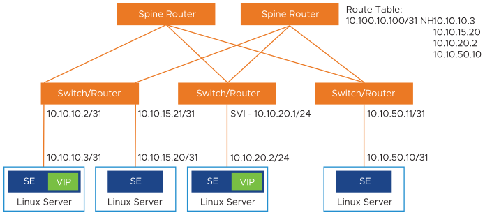
Scaling
Scaling out/ in virtual services is supported. In this example, a virtual service is placed on the NSX Advanced Load Balancer SE on the 10.10.10.x network is scaled out to three additional NSX Advanced Load Balancer SEs.
Flow Resiliency During Scale-Out/In
A flow is a 5-tuple, such as, src-IP, src-port, dst-IP, dst-port, and protocol. Routers do a hash of the 5-tuple to pick which equal-cost path to use. When an SE scale-out occurs, the router is given yet another path to use, and its hashing algorithm can make different choices, as a result disrupting existing flows. To gracefully cope with this BGP-based scale-out issue, NSX Advanced Load Balancer supports resilient flow handling using IP-in-IP (IPIP) tunneling. The following sequence shows how this is done.
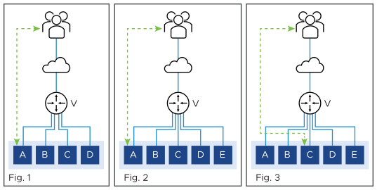
Figure 1 shows the virtual service placed on four SEs, with a flow ongoing between a client and SE-A. In figure 2, there is a scale-out to SE-E. This changes the hash on the router. Existing flows get rehashed to other SEs. In this particular example, suppose it is SE-C.
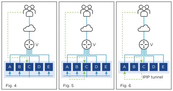
In the NSX Advanced Load Balancer implementation, SE-C sends a flow probe to all other SEs (figure 4). Figure 5 shows SE-A responding to claim ownership of the depicted flow. In figure 6, SE-C uses IPIP tunneling to send all packets of this flow to SE-A.
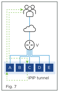
In figure 7, SE-A continues to process the flow and sends its response directly to the client.
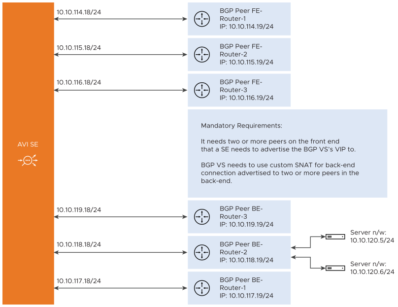
Flow Resiliency for Multi-homed BGP Virtual Service
The flow resiliency is supported when there is a BGP virtual service that is configured to advertise its VIP to more than one peer in the front end and is configured to advertise SNAT IP associated with virtual service to more than one peer in the back end.
In such a setup, when one of the links goes down, the BGP withdraws the routes from that particular NIC causing rehashing of that flow to another interface on the same SE or to another SE. The new SE that receives the flow tries to recover the flow with a flow probe which fails because of the interface going down.
The problem is seen with both the front end and the back end flows.
For the front end flows to be recovered, the flows must belong to a BGP virtual service that is placed on more than one NIC on a Service Engine.
For the back end flows to be recovered, the virtual service must be configured with SNAT IPs and must be advertised through BGP to multiple peers in the back end.
Recovering Frontend Flows
- Flow recovery within the same SE:
-
If the interface goes down, the FT entries are not deleted. If the flow lands on another interface, the flow-probe is triggered which is going to migrate the flow from the old flow table to the new interface where the flow is landed.
The interface down event is reported to the Controller and the Controller removes the VIP placement from the interface. This causes the primary virtual service entry to be reset. If the same flow now lands on a new interface, it triggers a flow-probe, flow-migration if the virtual service was placed initially on more than one interface.
- Flow recovery on a scaled-out SE:
-
If the flow lands on a new SE, the remote flow-probes are triggered. A new flag called relay will be added to the flow-probe message. This flag indicates that all the receiving interfaces need to relay the flow-probes to other flow-tables where the flow can be there. The flag is set at the sender of the flow-probe when the virtual service is detected as BGP scaled-out virtual service.
On the receiving SE, the messages are relayed to the other flow tables resulting in a flow migration. So subsequent flow-probe from the new SE is going to earn a response because the flow now resides on the interface that is up and running.
If there is more than one interface on the flow-probe receiving SE, they will all trigger a flow-migrate.
Recovering Backend Flows
The back end flows can be migrated only if the SNAT IP is used for the backend connection. When multiple BGP peers are configured on the back end, and the servers are reachable through more than one route, SNAT IP is placed on all the interfaces. Also, the flow table entries are created on all the interfaces in the back end.
This results in the flow getting recovered in case an interface fails, and the flow lands on another interface with flow table entry.
Message Digest5 (MD5) Authentication
BGP supports an authentication mechanism using the Message Digest 5 (MD5) algorithm. When authentication is enabled, any TCP segment belonging to BGP exchanged between the peers, is verified and accepted only if authentication is successful. For authentication to be successful, both the peers must be configured with the same password. If authentication fails, the BGP peer session will not be established. BGP authentication can be very useful because it makes it difficult for any malicious user to disrupt network routing tables.
Enabling MD5 Authentication for BGP
To enable MD5 authentication, specify md5_secret in the respective BGP peer configuration. MD5 support is extended to OpenShift cloud where the Service Engine runs as docker container but peers with other routers masquerading as host.
Mesos Support
BGP is supported for north-south interfaces in Mesos deployments. The SE container that is handling the virtual service will establish a BGP peer session with the BGP router configured in the BGP peering profile for the cloud. The SE then injects a /64 route (host route) to the VIP, by advertising the /64 to the BGP peer.
The following requirements apply to the BGP peer router:
The BGP peer must allow the SE’s IP interfaces and subnets in its BGP neighbor configuration. The SE will initiate the peer connection with the BGP router.
For eBGP, the peer router will detect the time-to-live (TTL) value decremented for the BGP session. This can prevent the session from coming up. This issue can be prevented from occurring by setting the eBGP multi-hop TTL. For example, on Juniper routers, the eBGP multi-hop TTL must be set to 64.
To enable MD5 authentication, select md5_secret in the respective BGP peer configuration. MD5 support is extended to OpenShift cloud where the Service Engine runs as docker container but peers with other routers masquerading as host.
Enabling BGP Features in NSX Advanced Load Balancer
Configuration of BGP features in NSX Advanced Load Balancer is accomplished by configuring a BGP profile, and by enabling RHI in the virtual service’s configuration.
Configure a BGP profile. The BGP profile specifies the local Autonomous System (AS) ID that the NSX Advanced Load Balancer SE and each of the peer BGP routers are in, and the IP address of each peer BGP router.
Enable the Advertise VIP using the BGP option on the Advanced tab of the virtual service’s configuration. This option advertises a host route to the VIP address, with the NSX Advanced Load Balancer SE as the next hop.
When BGP is configured on global VRF on LSC in-band, BGP configuration is applied on SE only when a virtual service is configured on the SE. Till then peering between SE and peer router will not happen.
