


VMware NSX-T provides an agile software-defined infrastructure to build cloud-native application environments. NSX-T is focused on providing networking, security, automation, and operational simplicity for emerging application frameworks and architectures that have heterogeneous endpoint environments and technology stacks. This topic describes the design details of the NSX Advanced Load Balancer - NSX-T integration.
NSX-T supports cloud-native applications, bare metal workloads, multi-hypervisor environments, public clouds, and multiple clouds. For more information on VMware NSX-T, see VMware NSX-T documentation.
Architecture
The solution comprises the NSX Advanced Load Balancer Controller which uses APIs to interface with the NSX-T manager and vCenter to discover the infrastructure. It also manages the lifecycle and network configuration of Service Engines (SE). The Controller provides the control plane and management console for users to configure the load balancing for their applications and the Service Engine provide a distributed and elastic load balancing fabric.
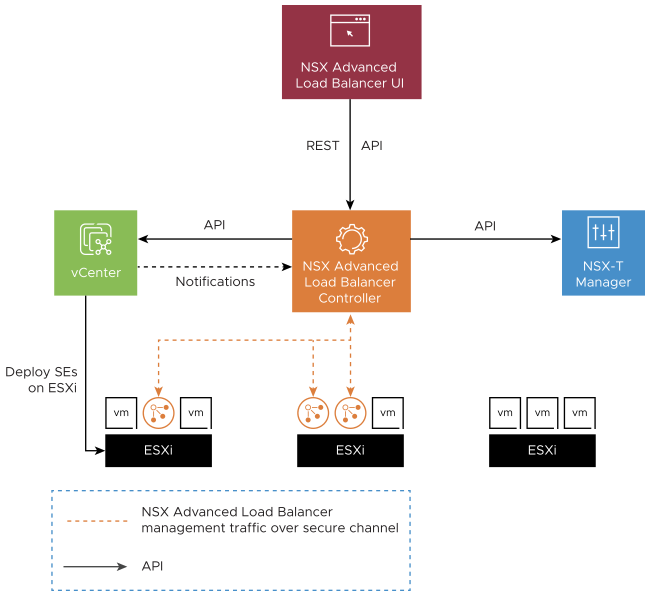
The NSX Advanced Load Balancer Controller uploads the SE OVA image to the content library on vCenter and uses vCenter APIs to deploy the SE VMs. A content library must be created by vCenter admin, before cloud configuration. For more information, see Creating a Content Library.
Protocol Port Requirements
The table below shows the protocols and ports required for the integration:
Source |
Destination |
Protocol |
Port |
|---|---|---|---|
The NSX Advanced Load Balancer Controller management IP and cluster VIP |
NSX-T Manager management IP |
TCP |
443 |
The NSX Advanced Load Balancer Controller management IP and cluster VIP |
vCenter server management IP |
TCP |
443 |
For more information about the protocols and ports used by the NSX Advanced Load Balancer Controller and Service Engines, see VMware Ports and Protocols.
NSX admins must manage the NSX edge policies if NSX-T gateway firewall is enabled.
Supportability
For more information on NSX-T - NSX Advanced Load Balancer Support Matrix, see the interoperability matrix.
Load Balancer Topologies
The SE supports only one arm mode of deployment in NSX-T environments i.e. for a virtual service the Client to VIP traffic and SE to backend server traffic both use the same SE data interface. An SE VM has nine data interfaces so it can connect to multiple logical segments but each one will be in a different VRF and hence will be isolated from all other interfaces.
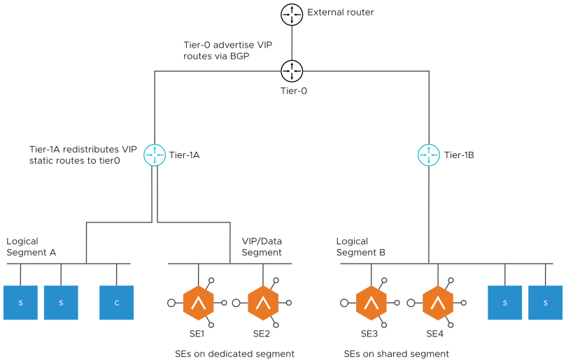
From shown in the diagram, two topologies are possible for SE deployment:
SEs on dedicated Logical Segment:
Allows to manage IP address assignment separately for SE interfaces
In the current version, this segment must be created on NSX-T prior to adding it to cloud configuration on Avi.
SEs on shared Logical Segment:
SE interfaces shares the same address space as the server VMs on same logical Segment.
Note:Only logical Segments connected to tier-1 router are supported. The cloud automation for NSX-T integration does not support placing SEs on logical segments directly connected to tier-0 routers.
Prior to NSX Advanced Load Balancer version 20.1.5, the NSX Advanced Load Balancer SE management network was required to be connected to an Overlay Logical Segment. Starting with NSX Advanced Load Balancer version 20.1.6, SE management network and data network can be connected to an NSX-T VLAN-backed logical segment. For more information, see NSX Advanced Load Balancer VLAN Logical Segment.
The following topologies are not supported:
SE Data
VIP Subnet
Client Subnet
Seg A-T1a-T0
Seg B-T1b-T0
Seg B-T1b-T0
Static route is configured on T1a.Therefore, only T1a AND T0 can do Proxy ARP . T1b does not have that static route so cannot proxy ARP for the VIP.
VIP Networking
For the virtual services placed on these SEs the VIP can belong to the subnet of the logical segment it is connected to or any other unused subnet. Once the virtual service is placed on the SE, the Controller updates the VIP static routes on the tier-1 router associated with the logical segment selected for the virtual service placement. The NSX admin is expected to configure the tier-1 router to redistribute these static routes with tier-0. For north-south reachability of the VIP, admin must configure the tier-0 to advertise the VIP routes to external router through BGP.
The number of VIPs that can be configured per Tier-1 is subject to the max static routes supported by the NSX Manager on the respective Tier-1 gateways. For more information on the logical routing limits, see NSX-T Data Center Configuration Limits.
There are two traffic scenarios as discussed below:
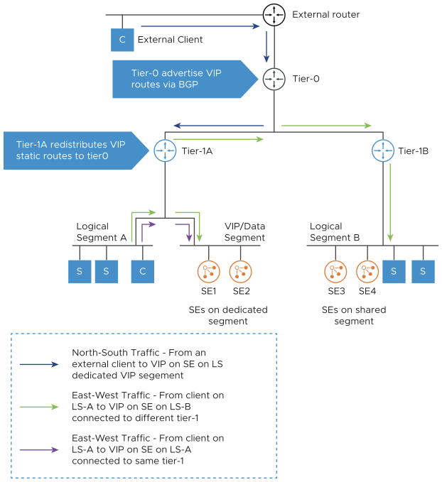
North-South Traffic
As shown in the figure above, when an external client sends request to the VIP it gets routed from the external router to tier-0 which forwards it to the correct tier-1, which routes it to the VIP on the SE.
East-West Traffic
For a client on the NSX overlay trying to reach a VIP, the request is sent to its default gateway on the directly connected tier-1. Depending on where the VIP is placed there can be 2 sub-scenarios:
VIP on the SE connected to a different tier-1: The traffic is routed to tier-0 which forwards the traffic to the correct tier-1 router. The tier-1 router then routes the traffic to the SE.
VIP on the SE connected to the same tier-1: The traffic is routed to the SE on same tier-1.
HA Modes and Scale Out
All HA modes (Active-Active, N+M and Active-Standby) are supported in NSX-T environment. When a VIP is placed on an SE, the Controller adds a static route for it on the tier-1 router, with the SE’s data interface as the next hop.
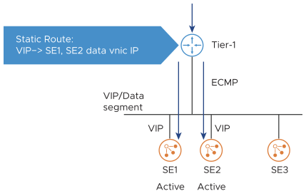
In the case of Active-Active and N+M HA modes, when the virtual service is scaled out, the Controller adds equal cost next hops pointing to each SE where the virtual service is placed. The tier-1 spreads out the incoming connections over the SEs, using Equal Cost Multi-Pathing (ECMP).
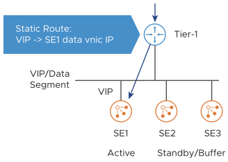
In case of Active-Standby where only one SE is Active or N+M HA mode with virtual service is not scaled out, the Avi controller programs route to the active SE only. ECMP is not required here.
Management Network
The NSX Advanced Load Balancer Controller Cluster VMs must be deployed adjacent to the NSX-T Manager, connected to the management port group. It is recommended to have a dedicated tier-1 gateway and logical segment for the NSX Advanced Load Balancer SE management.
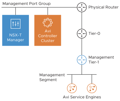
The first network interface of all SE VMs is connected to the management segment. The management IP address of the SEs must be reachable from the NSX Advanced Load Balancer Controller. For the load balacing (Virtual Servers/VIPs) to be advertised to external router, enable All Connected Segments & Service Ports and LB VIP under the Advertised Tier-1 Subnet settings of Tier-0 must advertise the learned routes to the external routers using BGP.
NSX-T Cloud Configuration Model
The point of integration in NSX Advanced Load Balancer, with any infrastructure, is called a cloud. For NSX-T environment, an NSX-T cloud has to be configured. For more information on configuring an NSX-T cloud, see Overview of NSX-T Integration with NSX Advanced Load Balancer.
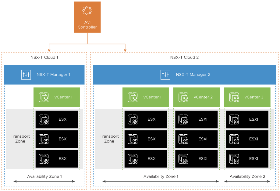
An NSX-T cloud is defined by an NSX-T manager and a transport zone. If an NSX-T manger has multiple transport zones, each will map to a new NSX-T cloud. To manage load balancing for multiple NSX-T environments each NSX-T manager will map to a new NSX-T cloud.
NSX-T cloud also requires the following configurations:
vCenter Objects
Each NSX-Cloud can have one or more vCenters associated to it. vCenter objects must be configured on NSX Advanced Load Balancer for all the vCenter compute managers added to the NSX-T that has ESXi hosts and that belong to the transport zone configured in the NSX-T cloud.
Select a content library where the NSX Advanced Load Balancer Controller will upload the SE OVA.
Network Configurations
The NSX-T cloud requires two types of network configurations: Management Network: The logical segment to be used for management connectivity of the SE VMs has to be selected.
VIP Placement Network: The NSX Advanced Load Balancer Controller will not sync all the NSX-T logical segments. The tier-1 router and one connected logical segment must be selected as the VIP network. Only one VIP network is allowed per tier-1 router. This can be repeated if there are multiple tier-1 routers. Only the selected VIP Logical Segments will be synced as Network objects on the NSX Advanced Load Balancer. The number of VIPs that can be configured per Tier-1 is subjected to the max static routes supported by the NSX manager on respective Tier-1s. For more information, see Routes Per Distributed Router in the config max tool.
VRF Contexts
The NSX Advanced Load Balancer automatically creates a VRF context for every tier-1 gateway selected during VIP network configuration. This is done because the logical Segments connected to different Tier-1s can have the same subnet. A VRF must be selected while creating a virtual service so that the VIPs are placed on the correct local segment and the VIP routes get configured on the correct tier-1 router.
Pool Configuration
For a given virtual service, the logical segment of the pool servers and the logical segment of the VIP must belong to the same tier-1 router. If the VIP and the pool are connected to different tier-1, the traffic might pass through the tier-0 and so through the NSX-T edge (depending on the NSX-T services configured by admin). This reduces the data path performance and so must be avoided. The pool members can be configured in two ways:
NSGroup: Servers can be added to an NSGroup in NSX-T manager and the same can be selected in the pool configuration. All the IP addresses that the NSGroup resolves to will be added as pool members on NSX Advanced Load Balancer. The NSX Advanced Load Balancer also polls for changes to NSGroup (default is every 5 min) and so if the NSGroup has dynamic membership or a member is manually added/removed the NSX Advanced Load Balancer pool will eventually sync the new server IPs.
IP Addresses: Static list of IP addresses can be specified as pool members.
Security Automation
Creating NSGroups for SEs and NSX Advanced Load Balancer Controller management IPs is automated by the NSX-T cloud.
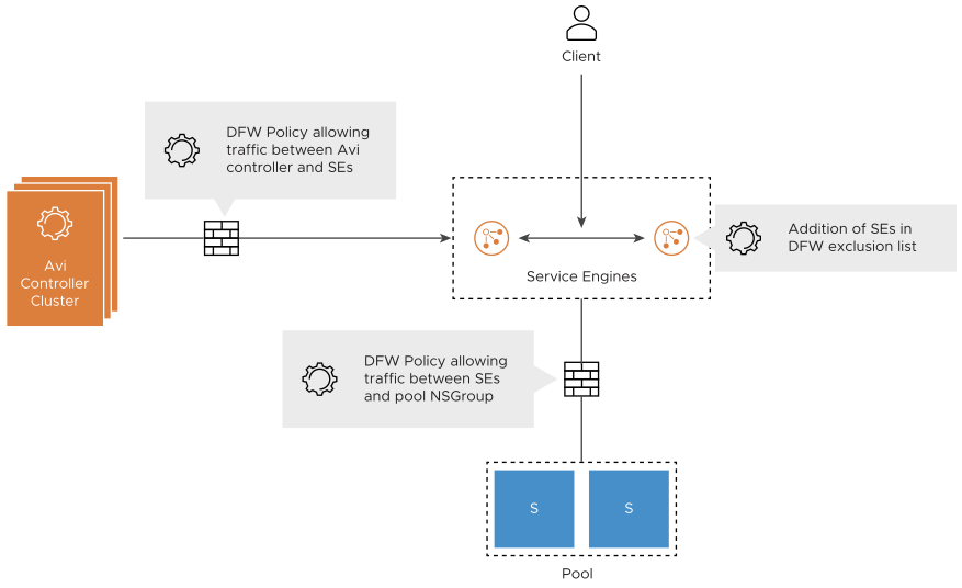
Run the following operations manually:
Add the SE NSGroup to the exclusion list. This is required to allow cross SE traffic and prevent packet drop due to stateful DFW when asymmetric routing of application traffic happens.
Create DFW policy to allow management traffic from SE NSGroup to NSX Advanced Load Balancer Controller NSGroup.
Note:The SE initiates the TCP connection to the Controller management IP
For every Virtual Service configured on NSX Advanced Load Balancer, create a DFW policy to allow traffic from SE NSGroup to the NSGroup/IP group configured as pool.
The NSX-T cloud connector creates and manages the NSGroups for different NSX Advanced Load Balancer objects. But the DFW rule creation is not supported currently. Add the service engine NSGroup to the exclusion list before virtual service creation.
If the SEs are in the exclusion list, DFW cannot be enforced on the Client to VIP traffic. This can be secured by configuring the network security policies on the virtual service on NSX Advanced Load Balancer. If the NSX-T gateway firewall is enabled, edge policies must be manually configured to allow VIP traffic form external clients.
If Preserve Client IP Address is enabled for a virtual service, the client IP will be sent to the server. This implies the following:
The DFW rule configured for the backend pool connectivity must allow Client IP to pass through DFW rule.
The health monitor is also sent from the SE interface to pool that must also be allowed in DFW rule.
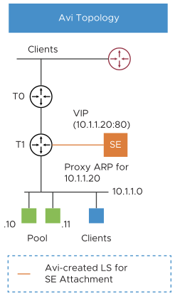
Proxy Arp for VIP on Tier-1 and Tier-0
In NSX Advanced Load Balancer-NSX-T 3.1.0 integration, the proxy ARP functionality is available on both Tier-0 and Tier-1 gateways for NSX Advanced Load Balancer LB VIPs.
Consider the following use cases:
Proxy ARP on Tier-0 Gateway: The client and VIP are in the same segment, but the client is reaching the VIP through the tier 0. Proxying of the ARP or the VIP will be done by tier 0 to the external clients.
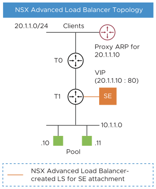
(Proxy ARP on Tier-1 Gateway): If the client is local, (on the same tier 1), tier 1 does the proxy ARP for the VIP. The SE and the tier 1 will respond, if they are attached.
For Tier 0 to do the proxy ARP, enable the All LB VIP Routes for Tier-1:
From the NSX-T manager, navigate to .
Add a Tier Gateway or edit an existing one.
Under Route Advertisement, enable All LB VIP Routes.
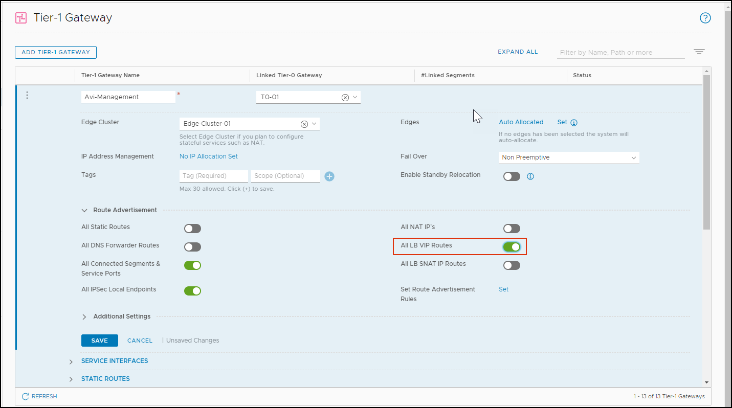
Click Save. From the image below, there are two proxy ARP virtual services created in two different clouds.
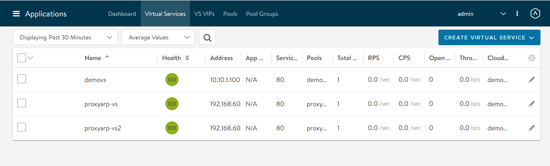
In these virtual services,
In ProxyVS1, the client and the VIP are in the same segment, the DataNIC is the same (seg50a)
In proxyVS2, the client and the VIP are in the same segment (seg50a), but the SE DataNIC is different (seg51a)
Configuring NSX API Rate Limits
NSX Manager applies a default rate limit to incoming client API calls. In large scale deployments, the rate of API calls made to NSX Manager by Avi Controller may exceed this rate limit, which can result in the error - HTTP 429 Too Many Requests response, and result in automation delays. The default rate limit is set to 100. Do not change the rate limit to 0.
The default rate limit can be modified by executing the following command on the NSX Manager CLI or API:
nsx1> set service http client-api-concurrency-limit [number]
nsx1> set service http client-api-rate-limit [number]
nsx1> set service http global-api-concurrency-limit [number]
Update the default rate limit using the NSX API PUT command, PUT https://<nsx-mgr-IP-address>/api/v1/node/services/http :
"client_api_concurrency_limit": 40,
"client_api_rate_limit": 100,
"global_api_concurrency_limit": 199,
For more information, see NSX 4.1.2 API.
Before changing or increasing the NSX API rate limit due to deployment requirements, validate the changes with Avi Load Balancer Support.
