


This section discusses how to verify the information that the DLR requires to route packets.
Let’s take a sample routed topology and create a set of logical switches and a DLR to create it in NSX.
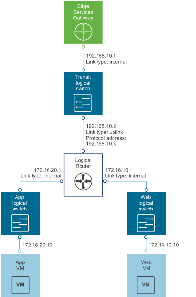
The diagram shows:
- 4 x Logical Switches, each with its own subnet
- 3 x VMs, connected one per logical switch
- Each with its own IP address and IP gateway
- Each with a MAC address (last two octets are shown)
- One DLR connected to the 4 logical switches; one logical switch is for the “Uplink," while the rest are Internal
- An external gateway, which could be an ESG, serving as an upstream gateway for the DLR.
The “Ready to complete” wizard screen shows for the DLR above.
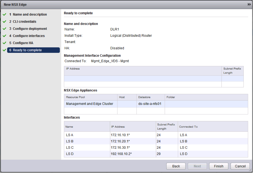
After the deployment of the DLR finishes, ESXi CLI commands can be used to view and validate the distributed state of the DLR in question on the participating hosts.
