You can configure NSX Manager, host transport nodes, and NSX Edge VMs on a single cluster. Each host in the cluster provides two physical NICs that are configured for NSX-T.
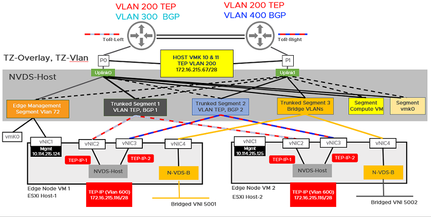
The topology referenced in this procedure uses:
- vSAN configured with the hosts in the cluster.
- A minimum of two physical NICs per host.
- vMotion and Management VMkernel interfaces.
Prerequisites
- All the hosts must be part of a vSphere cluster.
- Each host has two physical NIC cards enabled.
- Register all hosts to a vCenter Server.
- Verify on the vCenter Server that shared storage is available to be used by the hosts.
-
The host TEP IP and NSX Edge TEP IP must be in different VLAN segments. Any north-south traffic coming from host workloads is encapsulated in GENEVE and sent to an NSX Edge node with Source IP as host TEP and destination IP as NSX Edge TEP. Since these TEPs must belong to different VLANs or subnets, traffic must be routed through top-of-rack (TOR) switches. In this illustration, the transport VLAN used for the host is VLAN 200 and for NSX Edge is VLAN 600. The reason to configure separate VLAN for the host TEP and NSX Edge TEP is because a TEP can receive traffic from or send traffic to only on a physical network adapter but not from an internal port group.
Procedure
- Prepare four ESXi hosts with vmnic0 on vSS or vDS, vmnic1 is free.
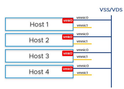
- On Host 1, install vCenter Server, configure a vSS/vDS port group, and install NSX Manager on the port group created on the host.
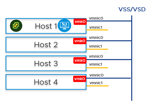
- Prepare ESXi hosts 1, 2, 3 and 4 to be transport nodes.
- Create VLAN transport zone and overlay transport zone with a named teaming policy. See Create Transport Zones.
- Create an IP pool or DHCP for tunnel endpoint IP addresses for the hosts. See Create an IP Pool for Tunnel Endpoint IP Addresses.
- Create an IP pool or DHCP for tunnel endpoint IP addresses for the Edge node. See Create an IP Pool for Tunnel Endpoint IP Addresses.
- Create an uplink profile with a named teaming policy. See Create an Uplink Profile.
Note: To optimally utilize the bandwidth available on uplinks, VMware recommends using teaming policy that distributes load across all available uplinks of the host.
- Configure a Network I/O Control profile to manage traffic on hosts. See Configuring Network I/O Control Profiles.
Note: VMware recommends to allocate 100 shares for management traffic.
- Configure hosts as transport nodes by applying a transport node profile. In this step, the transport node profile only migrates vmnic1 (unused physical NIC) to the N-VDS switch. After the transport node profile is applied to the cluster hosts, the N-VDS switch is created and vmnic1 is connected to the N-VDS switch. See Add a Transport Node Profile.
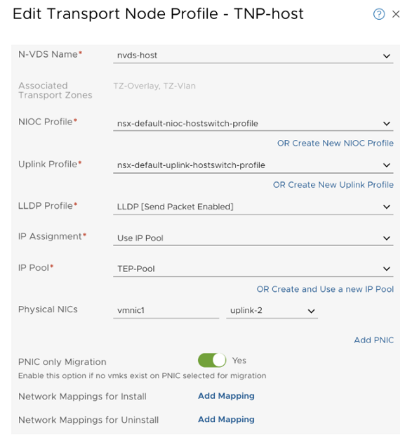
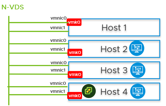
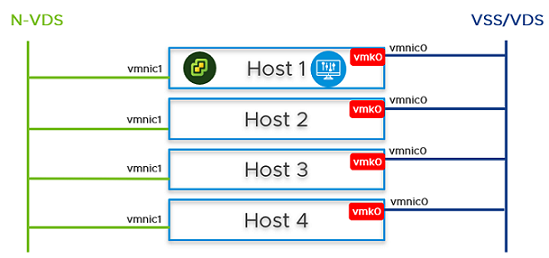 vmnic1 on all hosts are added to the N-VDS switch. So, out of the two physical NICs, one is migrated to the N-VDS switch. The vmnic0 interface is still connected to the vSS or vDS switch, which ensures connectivity to the host is available.
 - In the NSX Manager UI, create VLAN-backed segments for NSX Manager, vCenter Server, and NSX Edge. Ensure to select the correct teaming policy for each of the VLAN-backed segments. Do not use VLAN trunk logical switch as the target. When creating the target segments in NSX Manager UI, in the Enter List of VLANs field, enter only one VLAN value.
- On Host 2, Host 3, and Host 4, you must migrate the vmk0 adapter and vmnic0 together from VSS/VDS to N-VDS switch. Update the NSX-T configuration on each host. While migrating ensure
- vmk0 is mapped to Edge Management Segment .
- vmnic0 is mapped to an active uplink, uplink-1 .
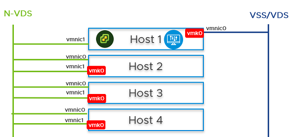
- In the vCenter Server, go to Host 2, Host 3, and Host 4, and verify that vmk0 adapter is connected to vmnic0 physical NIC on the N-VDS and must be reachable.
- In the NSX Manager UI, go to Host 2, Host 3, and Host 4, and verify both pNICs are on the N-VDSswitch.

- On Host 2 and Host 3, from the NSX Manager UI, install NSX Manager and attach NSX Manager to the segment. Wait for approximately 10 minutes for the cluster to form and verify that the cluster has formed.
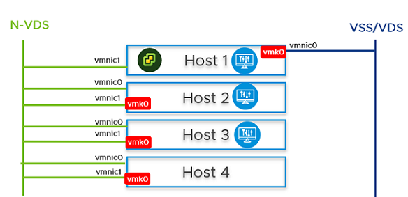
- Power off the first NSX Manager node. Wait for approximately 10 minutes.
- Reattach the NSX Manager and vCenter Server to the previously created logical switch. On host 4, power on the NSX Manager. Wait for approximately 10 minutes to verify that the cluster is in a stable state. With the first NSX Manager powered off, perform cold vMotion to migrate the NSX Manager and vCenter Server from host 1 to host 4.
For vMotion limitations, see https://kb.vmware.com/s/article/56991.
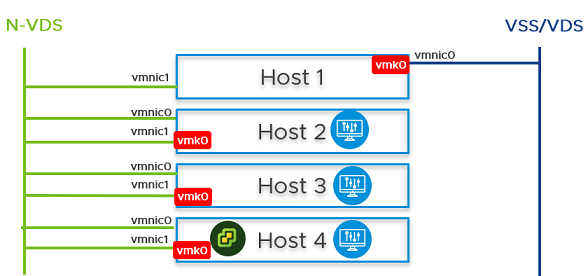
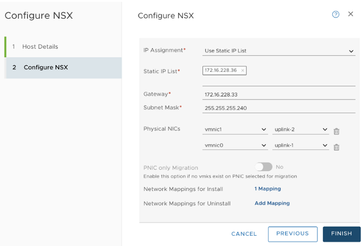
- From the NSX Manager UI, go to Host 1, migrate vmk0 and vmnic0 together from VSS to N-VDS switch.
- In the Network Mapping for Install field, ensure that the vmk0 adapter is mapped to the Edge Management Segment on the N-VDS switch.
- On Host 1, install the NSX Edge VM from the NSX Manager UI.
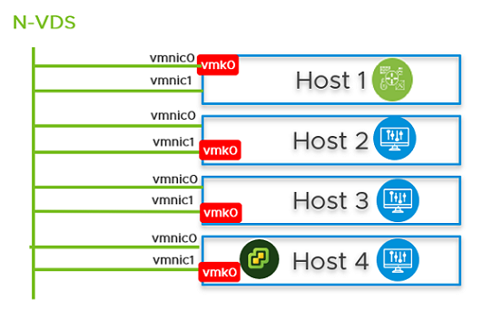
- Join the NSX Edge VM with the management plane.
- To establish the north-south traffic connectivity, configure NSX Edge VM with an external router.
- Verify that north-south traffic connectivity between the NSX Edge VM and the external router.
- If there is a power failure scenario where the whole cluster is rebooted, the NSX-T management component might not come up and communicate with N-VDS. To avoid this scenario, perform the following steps:
Caution: Any API command that is incorrectly run results in a loss of connectivity with the NSX Manager.Note: In a single cluster configuration, management components are hosted on an N-VDS switch as VMs. The N-VDS port to which the management component connects to by default is initialized as a blocked port due to security considerations. If there is a power failure requiring all the four hosts to reboot, the management VM port will be initialized in a blocked state. To avoid circular dependencies, it is recommended to create a port on N-VDS in the unblocked state. An unblocked port ensures that when the cluster is rebooted, the NSX-T management component can communicate with N-VDS to resume normal function.At the end of the subtask, the migration command takes the :
- UUID of the host node where the NSX Manager resides.
- UUID of the NSX Manager VM and migrates it to the static logical port which is in an unblocked state.
- In the NSX Manager UI, go to Manager Mode > Networking > Logical Switches tab (3.0 and later releases). Search for the Segment Compute VM segment. Select the Overview tab, find and copy the UUID. The UUID used in this example is, c3fd8e1b-5b89-478e-abb5-d55603f04452.
- Create a JSON payload for each NSX Manager.
- In the JSON payload, create logical ports with initialization status in UNBLOCKED_VLAN state by replacing the value for logical_switch_id with the UUID of the previously created Edge Management Segment.
- In the payload for each NSX Manager, the attachment_type_id and display_name values will be different.
Important: Repeat this step to create a total of four JSON files - three for NSX Managers and one for vCenter Server Appliance (VCSA).port1.json { "admin_state": "UP", "attachment": { "attachment_type": "VIF", "id": "nsxmgr-port-147" }, "display_name": "NSX Manager Node 147 Port", "init_state": "UNBLOCKED_VLAN", "logical_switch_id": "c3fd8e1b-5b89-478e-abb5-d55603f04452" }Where,admin_state: This is state of the port. It must UP.attachment_type: Must be set to VIF. All VMs are connected to NSX-T switch ports using a VIF ID.id: This is the VIF ID. It must be unique for each NSX Manager. If you have three NSX Managers, there will be three payloads, and each one of them must have a different VIF ID. To generate a unique UUID, log into the root shell of the NSX Manager and run /usr/bin/uuidgen to generate a unique UUID.display_name: It must be unique to help NSX admin identify it from other NSX Manager display names.init_state: With the value set toUNBLOCKED_VLAN, NSX unblocks the port for NSX Manager, even if the NSX Manager is not available.logical_switch_id: This is the logical switch ID of the Edge Management Segment.
- If there are three NSX Managers deployed, you need to create three payloads, one for each logical port of a NSX Manager. For example, port1.json, port2.json, port3.json.
Run the following commands to create payloads.
curl -X POST -k -u '<username>:<password>' -H 'Content-Type:application/json' -d @port1.json https://nsxmgr/api/v1/logical-portscurl -X POST -k -u '<username>:<password>' -H 'Content-Type:application/json' -d @port2.json https://nsxmgr/api/v1/logical-portscurl -X POST -k -u '<username>:<password>' -H 'Content-Type:application/json' -d @port3.json https://nsxmgr/api/v1/logical-portsAn example of API execution to create a logical port.
root@nsx-mgr-147:/var/CollapsedCluster# curl -X POST -k -u '<username>:<password>' -H 'Content-Type:application/json' -d @port1.json https://localhost/api/v1/logical-ports { "logical_switch_id" : "c3fd8e1b-5b89-478e-abb5-d55603f04452", "attachment" : { "attachment_type" : "VIF", "id" : "nsxmgr-port-147" }, "admin_state" : "UP", "address_bindings" : [ ], "switching_profile_ids" : [ { "key" : "SwitchSecuritySwitchingProfile", "value" : "fbc4fb17-83d9-4b53-a286-ccdf04301888" }, { "key" : "SpoofGuardSwitchingProfile", "value" : "fad98876-d7ff-11e4-b9d6-1681e6b88ec1" }, { "key" : "IpDiscoverySwitchingProfile", "value" : "0c403bc9-7773-4680-a5cc-847ed0f9f52e" }, { "key" : "MacManagementSwitchingProfile", "value" : "1e7101c8-cfef-415a-9c8c-ce3d8dd078fb" }, { "key" : "PortMirroringSwitchingProfile", "value" : "93b4b7e8-f116-415d-a50c-3364611b5d09" }, { "key" : "QosSwitchingProfile", "value" : "f313290b-eba8-4262-bd93-fab5026e9495" } ], "init_state" : "UNBLOCKED_VLAN", "ignore_address_bindings" : [ ], "resource_type" : "LogicalPort", "id" : "02e0d76f-83fa-4839-a525-855b47ecb647", "display_name" : "NSX Manager Node 147 Port", "_create_user" : "admin", "_create_time" : 1574716624192, "_last_modified_user" : "admin", "_last_modified_time" : 1574716624192, "_system_owned" : false, "_protection" : "NOT_PROTECTED", "_revision" : 0 - Verify that the logical port is created.

- Find out the VM instance ID for each of the NSX Manager. You can retrieve the instance ID from the Inventory → Virtual Machines, select the NSX Manager VM, select the Overview tab and copy the instance ID. Alternatively, search the instance ID from the managed object browser (MOB) of vCenter Server. Add :4000 to the ID to get the VNIC hardware index of an NSX Manager VM.
For example, if the instance UUID of the VM is
503c9e2b-0abf-a91c-319c-1d2487245c08, then its vnic index is503c9e2b-0abf-a91c-319c-1d2487245c08:4000. The three NSX Manager vnic indices are:mgr1 vnic: 503c9e2b-0abf-a91c-319c-1d2487245c08:4000mgr2 vnic: 503c76d4-3f7f-ed5e-2878-cffc24df5a88:4000mgr3 vnic: 503cafd5-692e-d054-6463-230662590758:4000 - Find out the transport node ID that hosts NSX Managers. If you have three NSX Manager , each hosted on a different transport node, note down the tranport node IDs. For example, the three transport node IDs are:
tn1: 12d19875-90ed-4c78-a6bb-a3b1dfe0d5eatn2: 4b6e182e-0ee3-403f-926a-fb7c8408a9b7tn3: d7cec2c9-b776-4829-beea-1258d8b8d59b - Retrieve the transport node configuration that is to be used as payloads when migrating the NSX Manager to the newly created port.
For example,
curl -k -u '<user>:<password' https://nsxmgr/api/v1/transport-nodes/12d19875-90ed-4c78-a6bb-a3b1dfe0d5ea > tn1.jsoncurl -k -u '<user>:<password' https://nsxmgr/api/v1/transport-nodes/4b6e182e-0ee3-403f-926a-fb7c8408a9b7 > tn2.jsoncurl -k -u '<user>:<password' https://nsxmgr/api/v1/transport-nodes/d7cec2c9-b776-4829-beea-1258d8b8d59b > tn3.json - Migrate the NSX Manager from the previous port to the newly created unblocked logical port on the Edge Management Segment. The VIF-ID value is the attachment ID of the port created previously for the NSX Manager.
The following parameters are needed to migrate NSX Manager:
- Transport node ID
- Transport node configuration
- NSX Manager VNIC hardware index
- NSX Manager VIF ID
The API command to migrate NSX Manager to the newly created unblocked port is:/api/v1/transport-nodes/<TN-ID>?vnic=<VNIC-ID>&vnic_migration_dest=<VIF-ID>For example,
root@nsx-mgr-147:/var/CollapsedCluster# curl -k -X PUT -u 'admin:VMware1!VMware1!' -H 'Content-Type:application/json' -d @<tn1>.json 'https://localhost/api/v1/transport-nodes/11161331-11f8-45c7-8747-34e7218b687f?vnic=5028d756-d36f-719e-3db5-7ae24aa1d6f3:4000&vnic_migration_dest=nsxmgr-port-147' - Ensure that the statically created logical port is Up.

- Repeat the preceding steps on every NSX Manager in the cluster.