


To take full advantage of the tier-0 logical router, the topology must be configured with redundancy and symmetry with BGP between the tier-0 routers and the external top-of-rack peers. This design helps to ensure connectivity in the event of link and node failures.
There are two modes of configuration: active-active and active-standby. The following diagram shows two options for symmetric configuration. There are two NSX Edge nodes shown in each topology. In the case of an active-active configuration, when you create tier-0 uplink ports, you can associate each uplink port with up to eight NSX Edge transport nodes. Each NSX Edge node can have two uplinks.
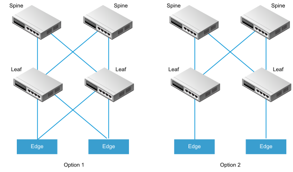
For option 1, when the physical leaf-node routers are configured, they should have BGP neighborships with the NSX Edges. Route redistribution should include the same network prefixes with equal BGP metrics to all of the BGP neighbors. In the tier-0 logical router configuration, all leaf-node routers should be configured as BGP neighbors.
When you are configuring the tier-0 router's BGP neighbors, if you do not specify a local address (the source IP address), the BGP neighbor configuration is sent to all NSX Edge nodes associated with the tier-0 logical router uplinks. If you do configure a local address, the configuration goes to the NSX Edge node with the uplink owning that IP address.
In the case of option1, if the uplinks are on the same subnet on the NSX Edge nodes, it makes sense to omit the local address. If the uplinks on the NSX Edge nodes are in different subnets, the local address should be specified in the tier-0 router's BGP neighbor configuration to prevent the configuration from going to all associated NSX Edge nodes.
For option 2, ensure that the tier-0 logical router configuration includes the tier-0 services router's local IP address. The leaf-node routers are configured with only the NSX Edges that they are directly connected to as the BGP neighbor.
