In this step, you specify the topology that will be migrated. This can be done through the NSX Manager UI or by using a mapping file in JSON format.
This mapping specifies how Edge Service Gateways (ESGs) and Distributed Logical Routers (DLRs) should map to gateways in
NSX-T. Before providing the mapping, evaluate your topology requirements and plan to do the following:
- Determine how you will map the ESGs and DLRs. The northbound ESGs without any L4-L7 services should be skipped. These are usually the ESGs peering with northbound routers and are in ECMP path. If you are using VPN on a northbound ESG, migrating to active-standby tier-0 is recommended. In other cases, migrating the ESGs/DLRs to tier-1 is recommended. An ESG and a DLR can be merged in one mapping entry.
- Create tier-0 and tier-1 gateways and configure dynamic or static routing on the tier-0 gateways towards the northbound routers based on your requirements. For dynamic routing you can choose to configure either BGP or OSPF, based on your NSX-V configuration. You need to manually configure this northbound routing.
- When configuring northbound routing, you must create and configure uplink interfaces on the NSX-T tier-0 gateway. The uplink interface subnet can be the same subnet as the NSX-V ESG northbound uplinks. The uplink interface IP addresses must be different from the IP addresses of the ESG uplinks.
- After configuring the dynamic routing on tier-0 gateways, check that the dynamic routing has converged, that is, BGP sessions are established or OSPF neighborships are FULL as applicable. After this, proceed with providing the mapping.
When defining a mapping, make sure that the following conditions are met. Note that a tier-1 distributed router (DR)-only gateway is a tier-1 gateway without any Edge cluster.
- A tier-0 gateway must have an uplink interface.
- A tier-1 DR-only gateway must be connected to a tier-0 gateway that has an uplink interface.
- When UDLR is mapped to a stretched tier-1 DR only, the stretched tier-0 to which it is connected must have an uplink on all sites.
- When UDLR is mapped to a stretched tier-0, the stretched tier-0 must have an uplink on all sites.
- When UDLR is mapped to an active-standby stretched tier-1, the primary site of this gateway must match the primary site of the connected stretched tier-0.
An example of a mapping file that maps ESGs to a tier-0 gateway:
[
  {
    "name":"nsxv-to-nsxt-mapping",
    "v_edges_to_policy_gateways_mappings":[
      {
        "v_edges":[
          "edge-1",
          "edge-2"
         ],
         "policy_gateway_name": "tier0-gateway"
         "policy_gateway_path": "/infra/tier-0s/tier0-gateway"
      }
    ]
  }
]
If you are doing a configuration migration, the above-mentioned mapping is not used for Advanced Load Balancer (ALB). Instead there is another optional mapping that you may provide for ALB. To specify that mapping, you must upload a JSON file. An example of a mapping file that maps ESGs to Service Engine groups:
{
  "alb": {
    "service_engine_group_per_esg": false,
    "esgs": [
      {
        "name": "edge-4",
        "interfaces": [
          {
            "name": "mgmt",
            "tier1_id": "London_Tier1Gateway1"
          },
          {
            "name": "vnic1",
            "placement_network_subnet": "172.16.1.10/16",
            "service_engine_group": "Test-SE-group"
          }
        ]
      }
    ]
  }
}
Starting with
NSX-T 3.2.1, you can migratie a cross-vCenter environment to NSX Federation. Here is a sample mapping file for such a migration:
[
    {
        "name": "london",
        "nsxv_id": "10.206.106.163",
        "nsxt_site_id": "1722c659-b0a9-4e70-b7ba-f264e057e1ea",
        "v_edges_to_policy_gateways_mappings": [
            {
                "v_edges": [
                    "edge-2"
                ]
                "policy_gateway_name": "Tier1Gateway1",
                "policy_gateway_path": "/infra/tier-1s/Tier1Gateway1"
            }
        ]
    },
    {
        "name": paris",
        "nsxv_id": "10.206.96.206",
        "nsxt_site_id": "00d3802e-5673-4791-b86d-71805a2c0aa6",
        "v_edges_to_policy_gateways_mappings": [
            {
                "v_edges": [
                    "edge-2"
                ]
                "policy_gateway_name": "Tier1Gateway1",
                "policy_gateway_path": "/infra/tier-1s/Tier1Gateway1"
            }
        ]
    },
    {
        "name": "site-GM",
        "nsxv_id": "10.206.106.163",
        "nsxt_site_id": "",
        "v_edges_to_policy_gateways_mappings": [
            {
                "v_edges": [
                    "edge-4e5065d6-d12d-49b1-a7da-5d9fcc7888f0"
                ]
                "policy_gateway_name": "Tier1Gateway1",
                "policy_gateway_path": "/infra/tier-1s/Tier1Gateway1"
            }
        ]
    },
]
If you are migrating a cross-vCenter environment to NSX Federation, note the following:
- Tier-0 gateways created on Local Manager must have an Edge cluster assigned.
- Tier-1 gateways created on Local Manager must either have an Edge cluster assigned or be connected to a tier-0 gateway that has an Edge cluster assigned.
- Tier-0 and tier-1 gateways created on Global Manager must span all the sites.
If you are using the Manager UI to do the mapping, tier-0 and tier-1 gateways that do not satisfy the above conditions are not shown in the dropdown list.
For more information about creating a mapping file for the load balancer, see Migrating NSX-V Load Balancer to Advanced Load Balancer.
Procedure
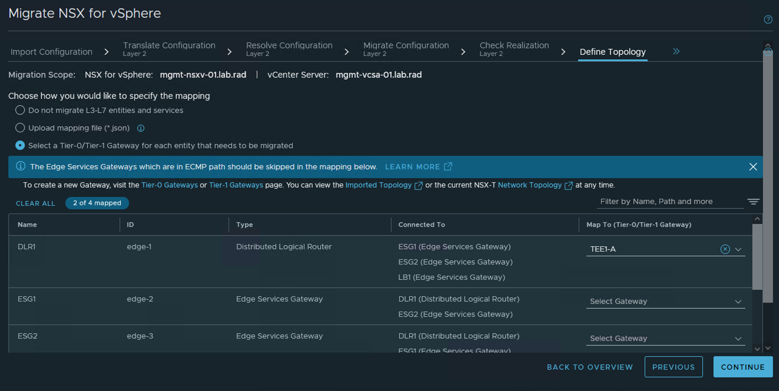
- Choose one of the following options:
- Do not migrate L3-L7 entities and services.
- Upload a mapping file (*.json).
- Select a Tier-0 or Tier-1 gateway for each entity that needs to be migrated.