


To do the Edge cutover migration, create a configuration file in a .json format and provide it as an input to the migration coordinator.
- List of NSX-V Edge appliances, which includes a Distributed Logical Router (DLR) or an Edge Services Gateway (ESG), or both:
- Edge ID of the Distributed Logical Router for Edge cutover.
- Edge ID of the Edge Services Gateway for migrating the DHCP leases, if DHCP service is configured on the Edge Services Gateway.
- The mapping of the NSX-V Edges to the name of the NSX tier-0 or tier-1 gateway.
[
    {
        "name": "ns-edge-cutover",
        "v_edges_to_policy_gateways_mappings": [
            {
                "v_edges": [
                    "edge-1",
                    "edge-2"
                ],
                "policy_gateway_name": "my_tier1"
            }
        ]
    }
]
| Parameter | Description | Data Type | Notes |
|---|---|---|---|
| name |
A name for this configuration. |
String |
This parameter is required. |
| v_edges_to_policy_gateways_mappings |
A list of mappings for the Edge cutover and DHCP lease migration. Each mapping consists of two parameters: v_edges and policy_gateway_name. See the next two rows for more details about these two parameters. |
Array |
This parameter is required. |
| v_edges |
A list of NSX-V Edge IDs. This list includes the Edge ID of the DLR for Edge cutover, or the Edge ID of an ESG for a DHCP lease migration, or both. |
Array of string values |
This parameter is required. Minimum: One Edge ID Maximum: Two Edge IDs per list Each Edge ID in the list must be unique. |
| policy_gateway_name | The desired mapping of the NSX-V Edges to the name of the NSX tier-0 or tier-1 gateway. |
String |
This parameter is required. The name must match exactly with the preconfigured NSX tier-0 or tier-1 gateway name. |
Example 1: Configuration File
Following figure shows the NSX-V environment that is configured in Topology 1 (ESG with High Availability and L4-L7 services). The equivalent NSX topology is shown to the right.
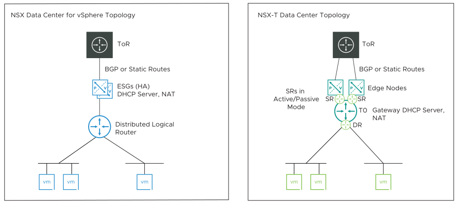
In this example, assume that NAT and DHCP server are configured on the ESG. In the NSX environment, you have configured these services on the tier-0 gateway. During Edge cutover, the DHCP leases on the ESG are migrated to the Gateway DHCP server on the tier-0 gateway.
[
    {
        "name": "ns-edge-cutover",
        "v_edges_to_policy_gateways_mappings": [
            {
                "v_edges": [
                    "edge-1",
                    "edge-2"
                ],
                "policy_gateway_name": "my_tier0"
            }
        ]
    }
]
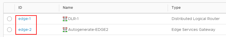
- edge-1 is the Edge ID of the Distributed Logical Router for Edge cutover.
- edge-2 is the Edge ID of the Edge Services Gateway where the DHCP service is configured.
- my_tier0 is the name of the NSX tier-0 gateway.
Example 2: Configuration File
Following figure shows the NSX-V environment that is configured in Topology 4 (One-Armed Load Balancer). The equivalent NSX topology is shown to the right.
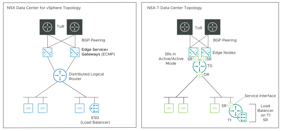
In this example, only a single-arm load balancer is configured on the ESG that is attached to the NSX-V Logical Switch. DHCP service is not running on this ESG. In the corresponding NSX topology, load balancer service is preconfigured on the tier-1 gateway (Service Interface) before the Edge cutover. When Edge cutover occurs, only the north-south traffic is migrated to the NSX Edge nodes. No DHCP lease migration is involved.
[
    {
        "name": "ns-edge-cutover",
        "v_edges_to_policy_gateways_mappings": [
            {
                "v_edges": [
                    "edge-1"
                ],
                "policy_gateway_name": "my_tier0"
            }
        ]
    }
]
- edge-1 is the Edge ID of the Distributed Logical Router for Edge cutover.
- my_tier0 is the name of the NSX tier-0 gateway.
Example 3: Configuration File
Following figure shows an NSX-V environment that is configured in Topology 4 (One-Armed Load Balancer). In this example, the ESG that is attached to the NSX-V Logical Switch has both load balancer and DHCP server running on it. The equivalent NSX topology is shown to the right. Remember that Gateway DHCP server and load balancer services are preconfigured in the NSX topology before the Edge cutover.
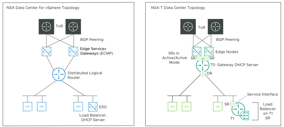
When Edge cutover occurs, the DHCP leases on the ESG that is attached to the Logical Switch are migrated to the Gateway DHCP server on the tier-0 gateway.
[
    {
        "name": "ns-edge-cutover",
        "v_edges_to_policy_gateways_mappings": [
            {
                "v_edges": [
                    "edge-1",
                    "edge-2"
                ],
                "policy_gateway_name": "my_tier0"
            }
        ]
    }
]
- edge-1 is the Edge ID of the Distributed Logical Router for Edge cutover.
- edge-2 is the Edge ID of the Edge Services Gateway where the DHCP service is configured. This ESG is attached to the NSX-V Logical Switch.
- my_tier0 is the name of the NSX tier-0 gateway.
Another alternative is to configure the NSX topology, as shown in the following figure. In this topology, the DHCP server profile is attached to a tier-1 gateway. The uplink of this tier-1 gateway is connected to the tier-0 gateway, and the NSX overlay segments are connected on the downlink of this tier-1 gateway
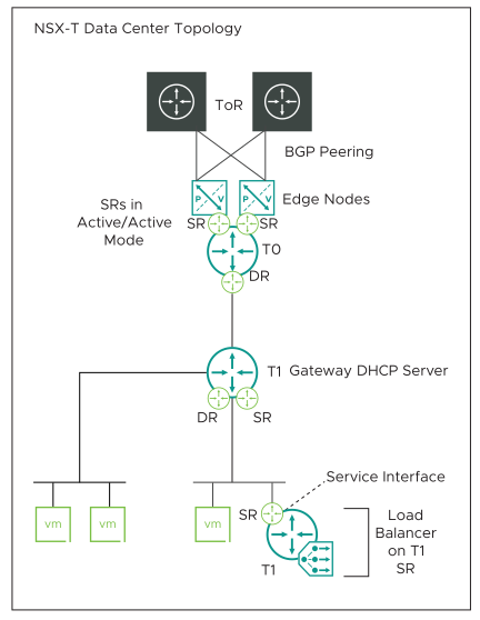
In this case, the migration coordinator migrates the DHCP leases to the Gateway DHCP server on the tier-1 gateway that is connected to the tier-0 gateway.
[
    {
        "name": "ns-edge-cutover",
        "v_edges_to_policy_gateways_mappings": [
            {
                "v_edges": [
                    "edge-1",
                    "edge-2"
                ],
                "policy_gateway_name": "my_tier1"
            }
        ]
    }
]
- edge-1 is the Edge ID of the Distributed Logical Router for Edge cutover.
- edge-2 is the Edge ID of the Edge Services Gateway where the DHCP service is configured. This ESG is attached to the NSX-V Logical Switch.
- my_tier1 is the name of the NSX tier-1 gateway that is connected to the tier-0 gateway.
