


You can migrate an NSX-V environment with vRealize Automation (vRA) if the topology is supported for migration.
- On-demand routed networks without services
- On-demand routed networks with DHCP server
- On-demand private networks (isolated networks)
- On-demand security groups
- On-demand outbound networks with NAT only
- On-demand outbound networks with DHCP, NAT, one-arm load balancer
- On-demand outbound networks with DHCP, NAT, inline load balancer
- On-demand outbound networks with DHCP, NAT, one-arm load balancer, inline load balancer
- On-demand one-arm load balancer on existing networks
- On-demand security groups or existing security groups with load balancer
- Existing security groups
- Existing networks (Logical Switches, VLAN Distributed Virtual Port Groups)
- Existing security groups
- Distributed Logical Router (DLR)
The version of vRA that you are using in your integrated environment must support the topologies mentioned below. For information about topologies that vRA supports for migration, see the vRealize documentation about migrating NSX-V to NSX.
In NSX-V, the default action for Edge firewall rules is to deny all traffic and then specific rules are added by vRA on the Edge to allow traffic for the services that it configures. However, in NSX the default behavior on the gateway is to allow all traffic.
- Before-migration topology
-
Objects that are pre-created or existing in
NSX-V are shown in a dark gray color. The pre-created topology in
NSX-V can match any one of the following four
NSX-V topologies that are supported for migration:
- ESG with High Availability and L4-L7 Services (Topology 1)
- ESG with No L4-L7 Services (Topology 2)
- Two Levels of ESG with L4-L7 Services on Second-Level ESG (Topology 3)
- One-Armed Load Balancer (Topology 4)
For details about these supported topologies, see Fixed Topologies Supported for End-to-End Migration.
The on-demand routed networks, outbound networks, and private networks that are shown in orange represent the resources that were created in vRealize Automation.
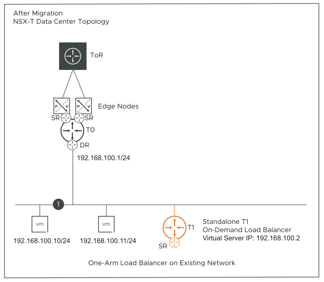
- After-migration topology
- The existing or pre-created objects in the NSX-V topology map to NSX objects in a dark gray color. The on-demand resources created in vRealize Automation map to NSX objects in an orange color.
- In all the supported topologies, vRealize Automation does not create Distributed Logical Router (DLR) or north-facing Edge Services Gateways (ESG). vRealize Automation can only consume an existing DLR in its Network Profile and use it for creating the on-demand routed networks.
- In all the supported topologies, both BGP and OSPF are supported between north-facing Edge Services Gateways and physical ToR switches.
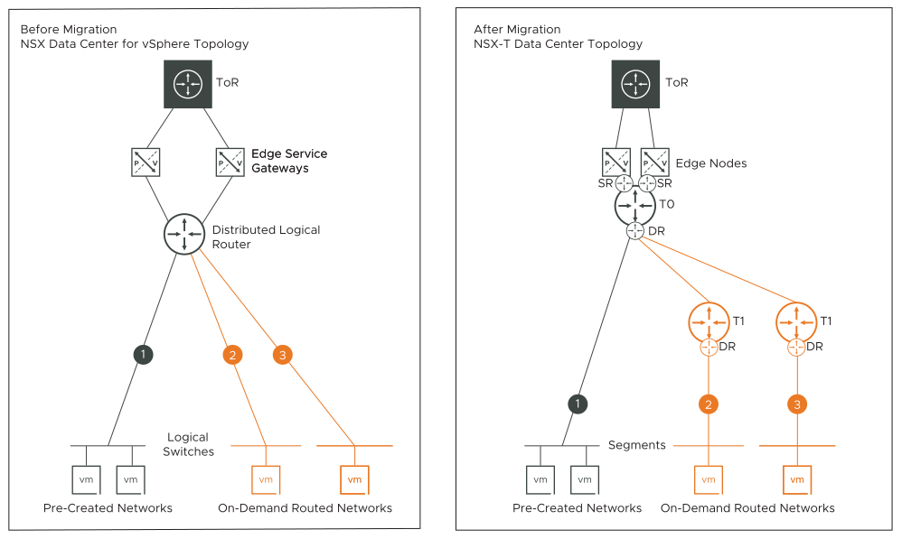
On-Demand Routed Networks Without Services (Topology A)
- Logical Switches created in vRealize Automation connect to an existing Distributed Logical Router in NSX-V.
- Workload VMs created using vRealize Automation are attached to the Logical Switches created in vRealize Automation.
- A tier-1 gateway is created for each vRealize Automation created Logical Switch that is connected to the Distributed Logical Router.
- The downlink interfaces of the Distributed Logical Router map to the downlink interfaces on the tier-1 gateway.
- An NSX segment is created for each vRealize Automation created Logical Switch.
- Workload VMs created in vRealize Automation are attached to the NSX segments.
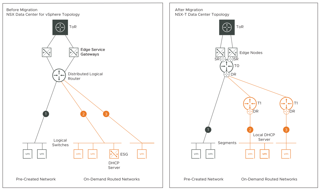
On-Demand Routed Networks with DHCP Server Only (Topology B)
- Logical Switches created in vRealize Automation connect to an existing Distributed Logical Router in NSX-V.
- An Edge Services Gateway with a DHCP server configuration is created using vRealize Automation.
- The Edge Services Gateway is attached to the vRealize Automation created Logical Switch.
- A tier-1 gateway is created for each vRealize Automation created Logical Switch that is connected to the Distributed Logical Router.
- The downlink interfaces of the Distributed Logical Router map to the downlink interfaces on the tier-1 gateway.
- An NSX segment is created for each vRealize Automation created Logical Switch.
- Workload VMs created in vRealize Automation are attached to the NSX segments.
- DHCP server configuration on the Edge Services Gateway is migrated to a Local DHCP server configuration on the NSX segment.
- DHCP leases of the workload VMs that are attached to the vRealize Automation created Logical Switch are migrated to NSX.
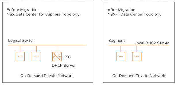
On-Demand Private Networks (Topology C)
- Workload VMs are created in vRealize Automation and attached to the vRealize Automation created Logical Switches.
- Optional: An Edge Services Gateway is created in vRealize Automation, and DHCP server is configured on this ESG. The ESG is attached to the vRealize Automation created Logical Switch.
- An NSX segment is created for each vRealize Automation created Logical Switch.
- Workload VMs created in vRealize Automation are attached to the NSX segment.
- Local DHCP server is configured on the NSX segment.
On-Demand Security Groups (Topology D)
- Add only VM vNICs as static members.
- Add Security Policies.
- Add firewall rules in the Security Policy. The rules can have a combination of IP addresses and applications, with or without port and protocol combinations.
- Apply Security Policies to the vRealize Automation created Security Groups.
If the firewall rules in the vRealize Automation created Security Policy contain IP addresses, vRealize Automation creates an IP set. If the rule contains port and protocol combinations, vRealize Automation creates the necessary applications in the firewall rule.
- An L7 application without port and protocol combination in an NSX-V firewall rule maps to a single Context Profile in an NSX firewall rule.
- An L7 application with port and protocol combination in an NSX-V firewall rule maps to a single Context Profile and a L4 service in an NSX firewall rule.
Existing Security Groups (Topology E)
In this topology, vRealize Automation consumes or references existing or pre-created Security Groups in the NSX-V environment. However, with existing Security Groups, limited functionality is supported. Using vRealize Automation, you can add only vNICs of workload VMs as static members in the existing Security Groups. You cannot create Distributed Firewall rules in vRealize Automation and apply them to existing Security Groups.
After migration, the Security Groups in NSX-V map to Groups in NSX. Security Tags created through vRealize Automation are not supported for migration to NSX. If you have assigned pre-created NSX-V Security Tags to workload VMs, these tags are migrated to NSX, but this information is not updated in vRealize Automation.
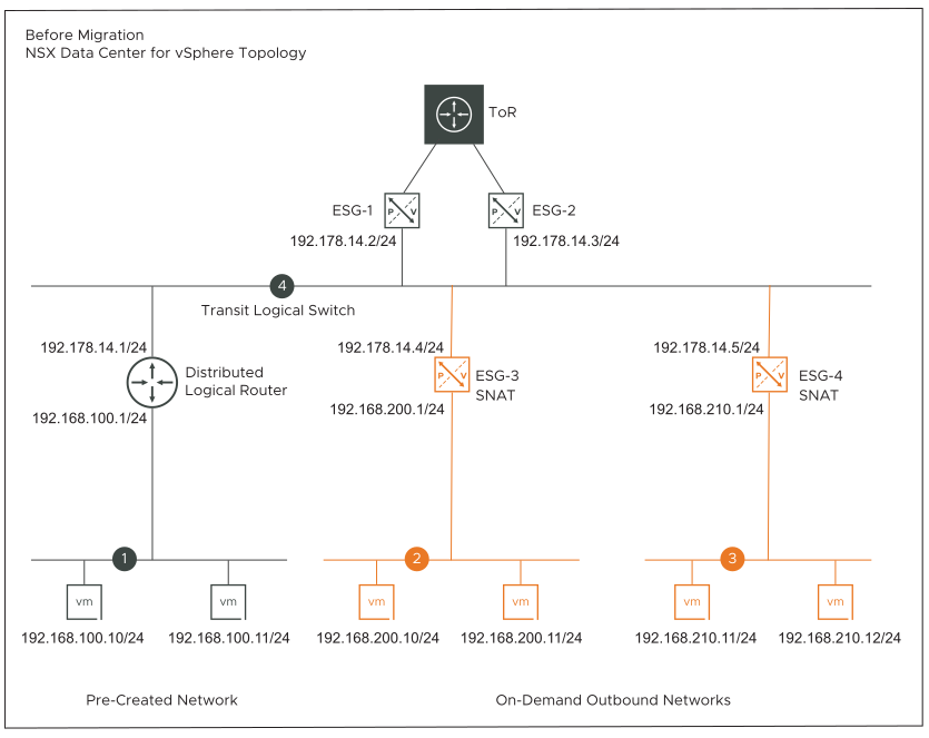
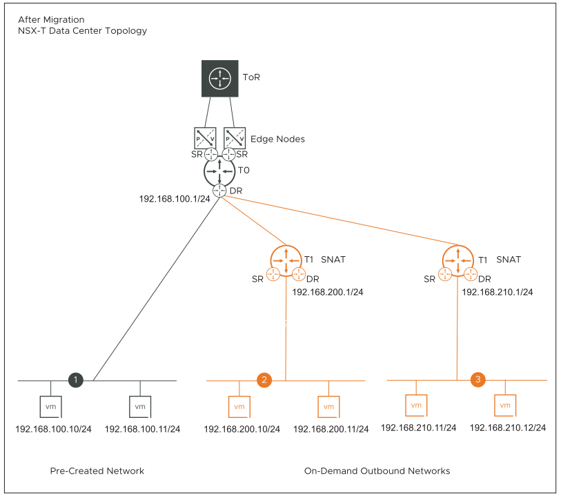
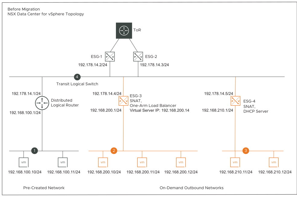
On-Demand Outbound Networks with NAT Only (Topology F)
- On-demand outbound networks (Logical Switches) are created using vRealize Automation. For example, networks 2 and 3 in the before migration topology represents the on-demand outbound networks.
- The uplink interface of the vRealize Automation created Edge Services Gateways (ESG-3 and ESG-4) are connected to an existing transit Logical Switch (192.178.14.0/24).
- The vRealize Automation created VMs on the on-demand outbound networks have a static IP address.
- Network address translation (NAT) rules are created using vRealize Automation. SNAT action is configured on the uplink interface of ESG-3 and ESG-4. The SNAT rules allow only outgoing traffic from the VMs on the outbound networks to the external clients on the public network. Port forwarding is not supported on vRealize Automation created SNAT rules.
Example: NAT rule configuration on ESG-3 and ESG-4.
ESG-3 ESG-4 Original
Action: SNAT
Applied on: vNIC (uplink interface)
Protocol: any
Source IP range: 192.168.200.1-192.168.200.14
Source ports: any
Destination IP range: any
Destination ports: any
Original
Action: SNAT
Applied on: vNIC (uplink interface)
Protocol: any
Source IP range: 192.168.210.1-192.168.210.14
Source ports: any
Destination IP range: any
Destination ports: any
Translated
IP address: 192.178.14.4
Port range: any
Translated
IP address: 192.178.14.5
Port range: any
- For each vRealize Automation created outbound network that is connected to an ESG, a tier-1 gateway is created and an NSX overlay segment is attached to the downlink of this tier-1 gateway.
- NAT rules with SNAT action are configured on the tier-1 gateways. These SNAT rules have the same configuration as the SNAT rules on the vRealize Automation created ESGs.
- Tier-1 gateways are created in the same edge cluster where the tier-0 gateway is created.
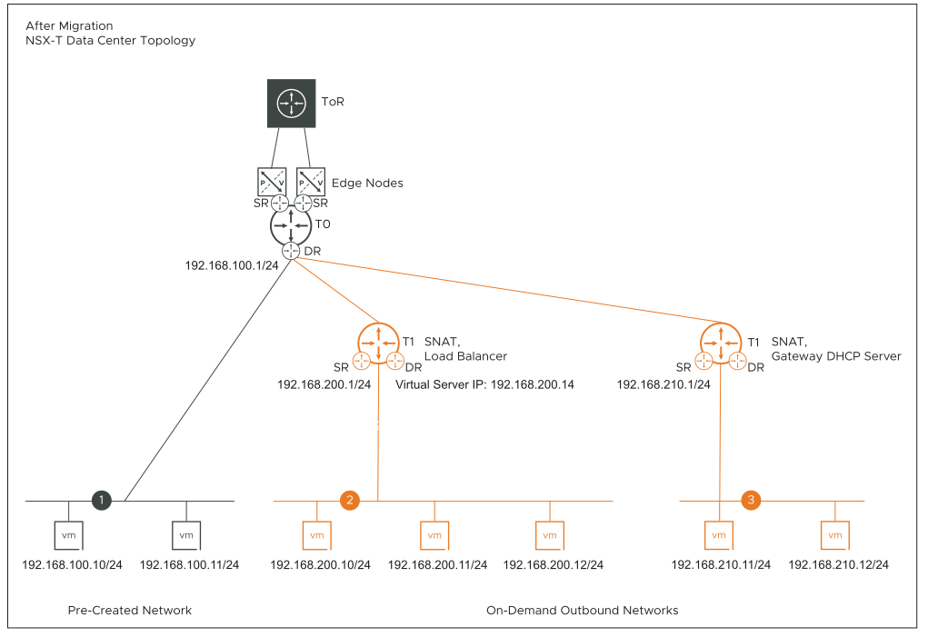
On-Demand Outbound Networks with DHCP, NAT, One-Arm Load Balancer (Topology G)
- On-demand outbound networks (Logical Switches) are created using vRealize Automation. For example, networks 2 and 3 in the before migration topology diagram represents the on-demand outbound networks.
- The uplink interface of the vRealize Automation created Edge Services Gateways (ESG-3 and ESG-4) are connected to an existing transit Logical Switch in NSX-V (for example, 192.178.14.0/24).
- ESG-3 is configured with a one-arm load balancer and NAT rules (SNAT action).
- ESG-4 is configured with a DHCP server and NAT rules (SNAT action).
- The vRealize Automation created VMs on the on-demand outbound network 2 have a static IP address.
- The vRealize Automation created workload VMs on the outbound network 3 are assigned an IP address by the DHCP server.
- Network address translation (NAT) rules are created using vRealize Automation. SNAT action is configured on the uplink interface of ESG-3 and ESG-4. SNAT rules allow only outgoing traffic from the VMs on the outbound networks to the external clients on the public network.
Example: NAT rule configuration on ESG-3 and ESG-4.
ESG-3 ESG-4 Original
Action: SNAT
Applied on: vNIC (uplink interface)
Protocol: any
Source IP range: 192.168.200.1-192.168.200.14
Source ports: any
Destination IP range: any
Destination ports: any
Original
Action: SNAT
Applied on: vNIC (uplink interface)
Protocol: any
Source IP range: 192.168.210.1-192.168.210.14
Source ports: any
Destination IP range: any
Destination ports: any
Translated
IP address: 192.178.14.4
Port range: any
Translated
IP address: 192.178.14.5
Port range: any
- Example: One-arm load balancer configuration on ESG-3:
- Virtual Server IP: 192.168.200.14
- Default Pool: Pool-1
- Pool-1 has three VMs: 192.168.200.10/24, 192.168.200.11/24, 192.168.200.12/24
The other load balancer configuration settings are not listed here because they are not of interest in this migration example.
- Example: Internal interface of ESG-3 has two IP addresses configured: primary IP address and secondary IP address.
- Primary IP address: 192.168.200.1/24. It connects the outbound network to the downlink (internal) interface of the ESG-3.
- Secondary IP address: 192.168.200.14/24. It is used as the virtual server IP.
If necessary, you can configure a single IP address on the internal interface of the ESG-3. In that case, the virtual server IP is the same as the primary IP address.
- Example: DHCP server configuration on ESG-4:
- DHCP pool range: 192.168.210.20-192.168.210.40
- Default gateway: 192.168.210.1
The other DHCP server settings are not listed here because they are not of interest in this migration example.
- For each vRealize Automation created outbound network that is connected to an ESG, a tier-1 gateway is created and an NSX overlay segment is attached to the downlink of this tier-1 gateway.
- NAT rules with SNAT action are configured on the tier-1 gateways. These SNAT rules have the same configuration as the SNAT rules on the vRealize Automation created ESGs.
- Tier-1 gateways are created in the same edge cluster where the tier-0 gateway is created.
- Load balancer service configuration on ESG-3 is migrated to a load balancer service configuration on the tier-1 gateway. This tier-1 gateway is connected to the NSX overlay segment 2 on the downlink.
- DHCP service configuration on ESG-4 is migrated to a Gateway DHCP server configuration on the tier-1 gateway. This tier-1 gateway is connected to the NSX overlay segment 3 on the downlink.
Migration coordinator uses a default DHCP server IP address to configure the Gateway DHCP server in NSX. If necessary, you can enter a different server IP address during the Resolve Configuration step of the migration. Follow the instructions that are shown on the Submit Input page of the migration coordinator UI to specify a different server IP address.
- In NSX-V, lease time is configured at the level of DHCP IP pool, whereas in NSX lease time is configurable at the level of each segment. If the DHCP service on an NSX-V network is configured with multiple DHCP IP pools, migration coordinator takes the highest lease time from among all the DHCP IP pools and configures it on the NSX segment.
- DHCP leases of the workload VMs that are attached to the vRealize Automation created outbound network 3 are migrated to NSX.
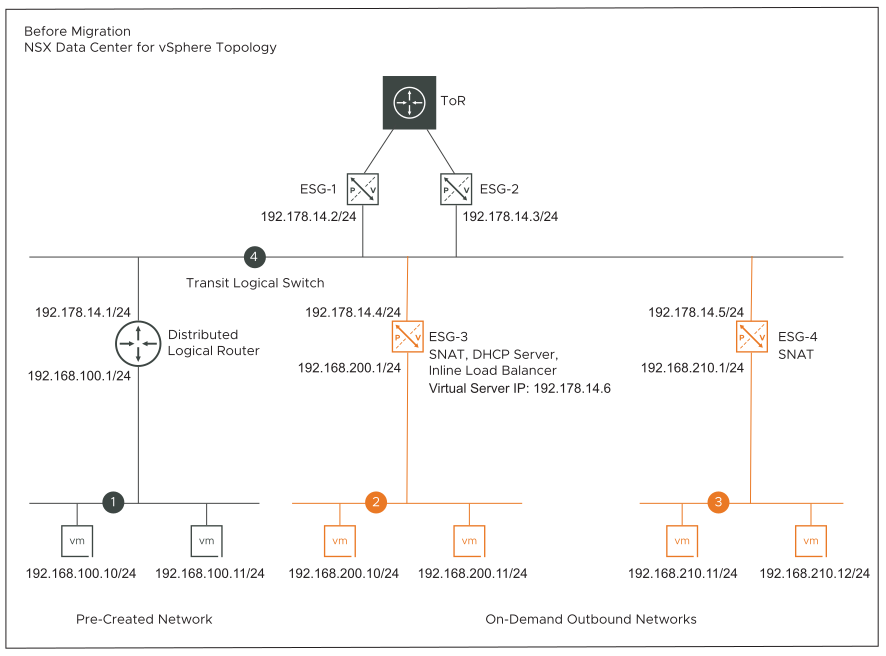
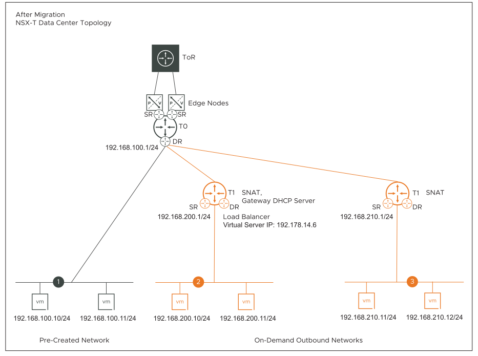
On-Demand Outbound Networks with DHCP, NAT, Inline Load Balancer (Topology H)
- On-demand outbound networks (Logical Switches) are created using vRealize Automation. For example, networks 2 and 3 in the before migration topology diagram represents the on-demand outbound networks.
- The uplink interfaces of the vRealize Automation created Edge Services Gateways (ESG-3 and ESG-4) are connected to an existing transit Logical Switch in NSX-V (for example, 192.178.14.0/24).
- ESG-3 is configured with an inline load balancer, DHCP server, and NAT rules (SNAT action).
- ESG-4 is configured with only NAT rules (SNAT action).
- The vRealize Automation created VMs on the on-demand outbound network 2 are assigned an IP address by the DHCP server.
- The vRealize Automation created VMs on the on-demand outbound network 3 have a static IP address.
- Network address translation (NAT) rules are created using vRealize Automation. SNAT action is configured on the uplink interface of ESG-3 and ESG-4. SNAT rules allow only outgoing traffic from the VMs on the outbound networks to the external clients on the public network.
For an example of NAT rule configuration on ESG-3 and ESG-4, see the before migration topology description of Topology G that is explained earlier in this topic.
- Example: Inline load balancer configuration on ESG-3:
- Virtual Server IP: 192.178.14.6
- Default Pool: Pool-1
- Pool-1 has two VMs: 192.168.200.10/24, 192.168.200.11/24
The other load balancer configuration settings are not listed here because they are not of interest in this migration example.
- Example: Uplink interface of ESG-3 has two IP addresses configured: primary IP address and secondary IP address.
- Primary IP address: 192.178.14.4/24. It connects ESG-3 to the transit Logical Switch.
- Secondary IP address: 192.178.14.6/24. It is used as the virtual server IP.
- Example: DHCP server configuration on ESG-3:
- DHCP pool range: 192.168.200.20-192.168.200.40
- Default gateway: 192.168.200.1
The other DHCP server settings are not listed here because they are not of interest in this migration example.
- For each vRealize Automation created outbound network that is connected to an ESG, a tier-1 gateway is created and an NSX overlay segment is attached to the downlink of this tier-1 gateway.
- NAT rules with SNAT action are configured on the tier-1 gateways. These SNAT rules have the same configuration as the SNAT rules on the vRealize Automation created ESGs.
- Tier-1 gateways are created in the same edge cluster where the tier-0 gateway is created.
- Load balancer service on ESG-3 is migrated to a load balancer service on the tier-1 gateway. This tier-1 gateway is connected to the NSX overlay segment 2 on the downlink.
- DHCP service configuration on ESG-3 is migrated to a Gateway DHCP server on the tier-1 gateway.
Migration coordinator uses a default DHCP server IP address to configure the Gateway DHCP server in NSX. If necessary, you can enter a different server IP address during the Resolve Configuration step of the migration. Follow the instructions that are shown on the Submit Input page of the migration coordinator UI to specify a different server IP address.
- In NSX-V, lease time is configured at the level of DHCP IP pool, whereas in NSX lease time is configurable at the level of each segment. If the DHCP service on an NSX-V network is configured with multiple DHCP IP pools, migration coordinator takes the highest lease time from among all the DHCP IP pools and configures it on the NSX segment.
- DHCP leases of the workload VMs that are attached to the vRealize Automation created outbound network 2 are migrated to NSX.
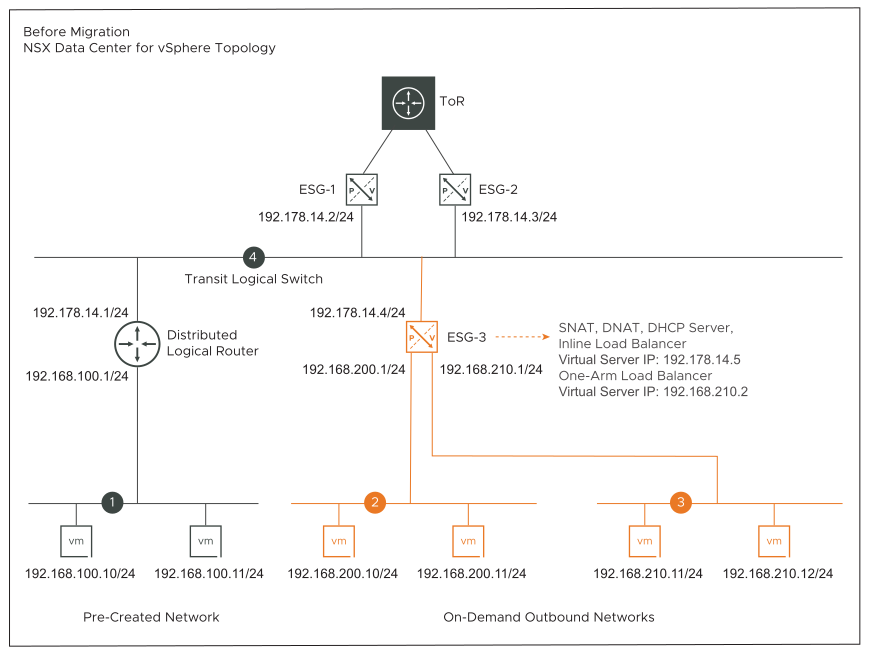
On-Demand Outbound Networks with DHCP, NAT, One-Arm Load Balancer, Inline Load Balancer (Topology I)
- On-demand outbound networks (Logical Switches) are created using vRealize Automation. For example, networks 2 and 3 in the before migration topology diagram represents the on-demand outbound networks.
- Both outbound networks are connected to the downlink interfaces of a single vRealize Automation created Edge Services Gateway (ESG-3). This topology diagram shows two outbound networks connected to ESG-3. However, you can have more than two outbound networks connected to the same ESG.
- The uplink interface of ESG-3 is connected to an existing transit Logical Switch in NSX-V (for example, 192.178.14.0/24).
- The following services are configured on ESG-3:
- NAT rules with SNAT and DNAT action.
- DHCP server
- One-arm load balancer
- Inline load balancer
- The vRealize Automation created VMs on the on-demand outbound networks 2 and 3 are assigned an IP address by the DHCP server.
- Example: Inline load balancer configuration on ESG-3. It load balances traffic on network 2:
- Virtual Server IP: 192.178.14.5
- Default Pool: Pool-1
- Pool-1 has two VMs: 192.168.200.10/24, 192.168.200.11/24
The other load balancer configuration settings are not listed here because they are not of interest in this migration example.
- Example: One-arm load balancer configuration on ESG-3. It load balances traffic on network 3:
- Virtual Server IP: 192.168.210.2
- Default Pool: Pool-2
- Pool-2 has two VMs: 192.168.210.11/24, 192.168.210.12/24
- NAT rules with SNAT action and DNAT action are configured on ESG-3. Port forwarding is supported for both SNAT and DNAT rules.
- Example: SNAT rules configuration on ESG-3.
SNAT Rule 1 SNAT Rule 2 Original
Applied on: vNIC (uplink interface)
Protocol: any
Source IP range: 192.168.200.1-192.168.200.14
Source ports: any
Destination IP range: any
Destination ports: any
Original
Applied on: vNIC (uplink interface)
Protocol: any
Source IP range: 192.168.210.1-192.168.210.14
Source ports: any
Destination IP range: any
Destination ports: any
Translated
IP address: 192.178.14.5
Port range: any
Translated
IP address: 192.178.14.4
Port range: any
- Example: DNAT rule configuration on ESG-3.
Original
Protocol: any
Source IP range: any
Source ports: any
Destination IP range: 192.178.14.5
Destination ports: 100
Translated
IP address: 192.178.200.35
Port range: 80
- Example: DHCP server configuration on ESG-3 has two IP pools:
- DHCP IP pool 1: 192.168.200.20-192.168.200.40
- Default gateway for pool 1: 192.168.200.1
- DHCP IP pool 2: 192.168.210.20-192.168.210.40
- Default gateway for pool 2: 192.168.210.1
The other DHCP server settings are not listed here because they are not of interest in this migration example.
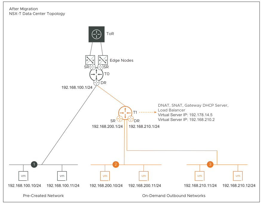
- For the vRealize Automation created outbound networks that are connected to a single ESG, a tier-1 gateway is created and NSX overlay segments are attached to the downlink of this tier-1 gateway.
- SNAT and DNAT rules are configured on the tier-1 gateway. These rules have the same configuration as the SNAT and DNAT rules on the vRealize Automation created ESG-3.
- Tier-1 gateway is created in the same edge cluster where the tier-0 gateway is created.
- Load balancer service configurations on ESG-3 are migrated to the load balancer service configurations on the tier-1 gateway.
- DHCP service configuration on ESG-3 is migrated to a Gateway DHCP server on the tier-1 gateway.
Migration coordinator uses a default DHCP server IP address to configure the Gateway DHCP server in NSX. If necessary, you can enter a different server IP address during the Resolve Configuration step of the migration. Follow the instructions that are shown on the Submit Input page of the migration coordinator UI to specify a different server IP address.
- In NSX-V, lease time is configured at the level of DHCP IP pool, whereas in NSX lease time is configurable at the level of each segment. When the DHCP service on an NSX-V network is configured with multiple DHCP IP pools, migration coordinator takes the highest lease time from among all the DHCP IP pools and configures it on the NSX segment.
- DHCP leases of the workload VMs that are attached to the vRealize Automation created outbound networks are migrated to NSX.
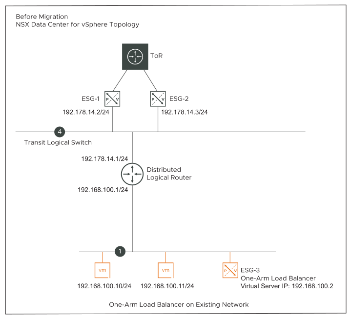
On-Demand One-Arm Load Balancer on Existing Networks (Topology J)
- A one-arm load balancer is configured on a vRealize Automation created ESG. This ESG is connected to an existing network in NSX-V. The existing network can either be a VLAN or a Logical Switch.
The before topology diagram shows a single one-arm load balancer on an existing network 1. For the purposes of this topology description, a single one-arm load balancer on a vRealize Automation created ESG is considered. However, this topology also supports the following configurations:
- Multiple vRealize Automation created one-arm load balancers connected to a single existing network. One load balancer is configured on each vRealize Automation created ESG. All ESGs are deployed as part of a single vRealize Automation deployment.
- Multiple vRealize Automation created one-arm load balancers, where one load balancer is connected to each different existing network. One load balancer is configured on each vRealize Automation created ESG. All ESGs are deployed as part of a single vRealize Automation deployment.
- The vRealize Automation created workload VMs that are connected to an existing network have a static IP address.
- Example: One-arm load balancer configuration on ESG-3.
- Virtual Server IP: 192.168.100.2
- Default Pool: Pool-1
- Pool-1 has two VMs: 192.168.100.10/24, 192.168.100.11/24
- ESG-3 in the NSX-V topology is migrated to a standalone tier-1 gateway in the NSX topology. This tier-1 gateway is not connected to the tier-0 gateway.
- The load balancer configuration on ESG-3 is migrated to a load balancer configuration on the tier-1 gateway.
On-Demand Security Groups or Existing Security Groups with Load Balancer (Topology K)
This topology supports a vRealize Automation created ESG with a single load balancer configured on it. The ESG can be connected either to an existing network or to an on-demand network that is created through vRealize Automation.
An existing Security Group is a part of the vRealize Automation Network Profile, or an on-demand/existing Security Group is present in the vRealize Automation deployment that contains on-demand networks.
In the input deployment configuration file, vRealize Automation automatically adds the virtual server IP of the load balancer inside an IP set object. This IP set is added as a member of the Security Group in the vRealize Automation Network Profile. Or the IP set is added as a member of the on-demand or existing Security Group from the blueprint that is associated with the load balanced pool members.
When such a topology is migrated to NSX, the ESG maps to a tier-1 gateway in the NSX topology. Load balancer service configuration on ESG is migrated to a load balancer service configuration on the tier-1 gateway. The Security Group in NSX-V maps to a Group in NSX. This NSX Group contains a nested Group that has the virtual server IP of the load balancer.
