


Device Settings allows you configure the Interface Settings for one or more Edge models in a profile.
Depending on the Edge Model, each interface can be a Switch Port (LAN) interface or a Routed (WAN) Interface. Depending on the Branch Model, a connection port is a dedicated LAN or WAN port, or ports can be configured to be either a LAN or WAN port. Branch ports can be Ethernet or SFP ports. Some Edge models may also support wireless LAN interfaces.
It is assumed that a single public WAN link is attached to a single interface that only serves WAN traffic. If no WAN link is configured for a routed interface that is WAN capable, it is assumed that a single public WAN link should be automatically discovered. If one is discovered, it will be reported to the SD-WAN Orchestrator. This auto-discovered WAN link can then be modified via the SD-WAN Orchestrator and the new configuration pushed back to the branch.
- If the routed Interface is enabled with the WAN overlay and attached with a WAN link, then the interface will be available for all Segments.
- If an interface is configured as PPPoE, it will only support a single auto-discovered WAN link. Additional links cannot be assigned to the interface.
If the link should not or cannot be auto-discovered, it must be explicitly configured. There are multiple supported configurations in which auto-discovery will not be possible, including:
- Private WAN links
- Multiple WAN links on a single interface. Example: A Datacenter Hub with 2 MPLS connections
- A single WAN link reachable over multiple interfaces. Example: for an active-active HA topology
Links that are auto-discovered are always public links. User-defined links can be public or private, and will have different configuration options based on which type is selected.
Public WAN Links
Public WAN links are any traditional link providing access to the public internet such as Cable, DSL, etc. No peer configuration is required for public WAN links. They will automatically connect to the SD-WAN Gateway, which will handle the dissemination of information needed for peer connectivity.
Private (MPLS) WAN Links
Private WAN links belong to a private network and can only connect to other WAN links within the same private network. Because there can be multiple MPLS networks, within a single enterprise, for example, the user must identify which links belong to which network. The SD-WAN Gateway will use this information to distribute connectivity information for the WAN links.
You may choose to treat MPLS links as a single link. However, to differentiate between different MPLS classes of service, multiple WAN links can be defined that map to different MPLS classes of service by assigning each WAN link a different DSCP tag.
Additionally, you may decide to define a static SLA for a private WAN link. This will eliminate the need for peers to exchange path statistics and reduce the bandwidth consumption on a link. Since probe interval influences how quickly the device can fail over, it’s not clear whether a static SLA definition should reduce the probe interval automatically.
Device Settings
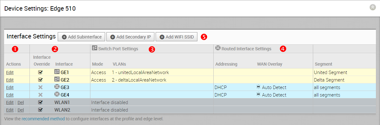
The following screen captures illustrate the top-level user interface for the SD-WAN Edge 500, SD-WAN Edge 1000, and introducing SD-WAN Edge 610 for the 3.4 release. The following table describes the major features of the UI (the numbers in the table correspond to the numbers in the subsequent screen captures).
| |
Actions you can perform on the network interface, such as Edit or Delete. |
| |
The Interface name. This name matches the Edge port label on the Edge device or is predetermined for wireless LANs. |
| |
The list of Switch Ports with a summary of some of their settings (such as Access or Trunk mode and the VLANs for the interface). Switch Ports are highlighted with a light yellow background. |
| |
The list of Routed Interfaces with a summary of their settings (such as the addressing type and if the interface was auto-detected or has an Auto Detected or User Defined WAN overlay). Routed Interfaces are highlighted with a light blue background. |
| |
The list of Wireless Interfaces (if available on the Edge device). You can add additional wireless networks by clicking the Add Wi-Fi SSID button. Wireless Interfaces are highlighted with a light gray background. |
| |
|
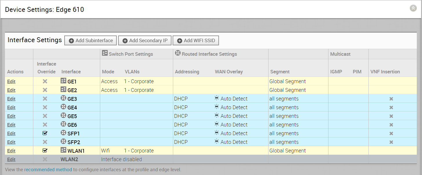
The 3.4 release introduces Edge 610.
For the 3.4 release, a new routed interface (CELL1) is added, if users choose Edge 510-LTE as the model, will be displayed in the Interface Settings area (see image below).
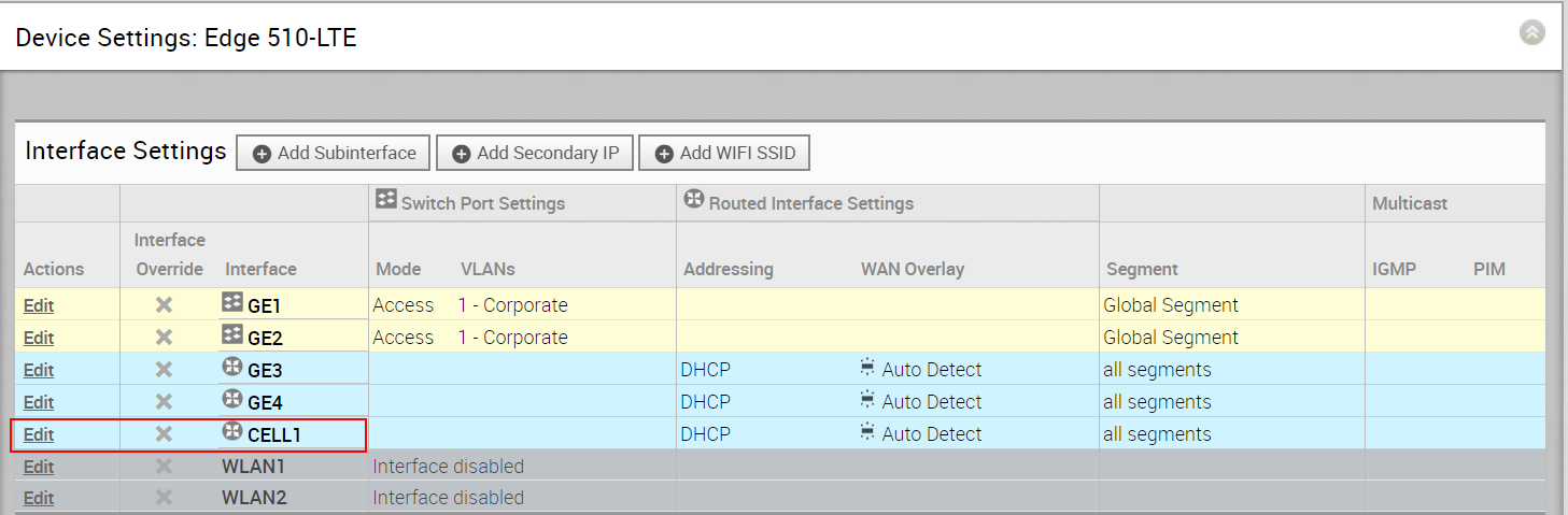
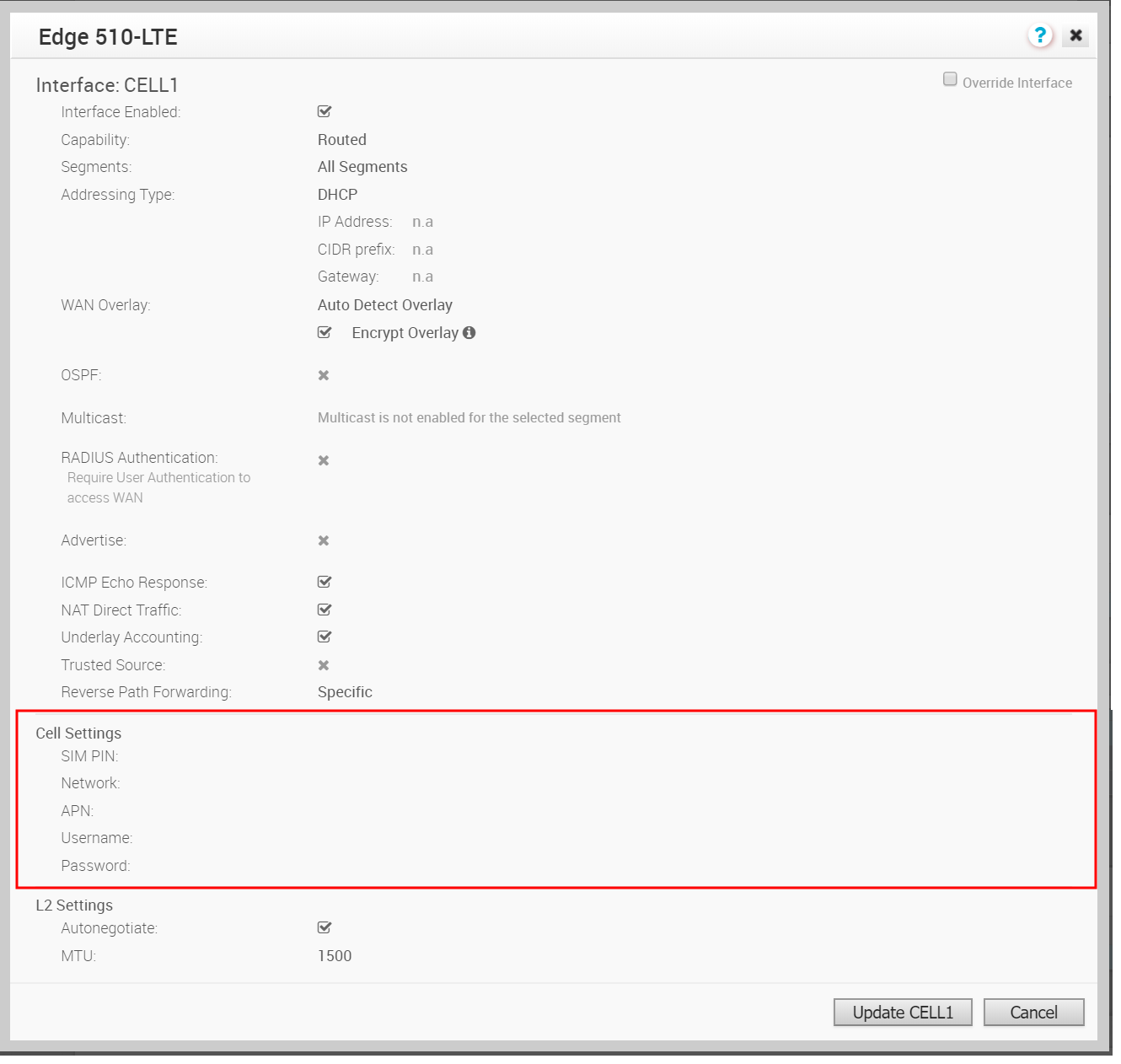
By clicking the Edit link, as shown in the image above, users can edit the Cell Settings section. (See image below).
Sub Interfaces and Secondary IPs
Adding a Sub Interface
When you add a sub interface to a routed interface, the sub interface gets a subset of the configuration options provided to the parent interface.
- Click the Add Sub Interface button.
- Select an Interface from the drop-down menu and the Sub Interface ID in the text box as shown in the Select Interface dialog below.
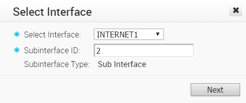
- Click Next.
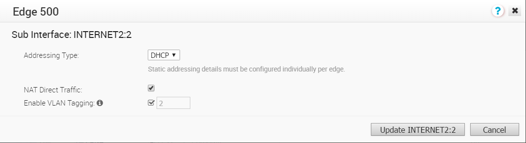
- In the Sub Interface dialog box, choose your Addressing Type ( DHCP or Static).
- If you choose the Addressing Type DHCP, the Enable VLAN Tagging checkbox is selected by default and the Sub Interface ID you chose in the previous dialog displays in the text box.
- If you choose the Addressing Type Static, you have the option of enabling VLAN by selecting the Enable VLAN Tagging check box. The Sub Interface ID you chose in the previous dialog displays in the text box.

- If you choose the Addressing Type DHCP, the Enable VLAN Tagging checkbox is selected by default and the Sub Interface ID you chose in the previous dialog displays in the text box.
- Check NAT Direct Traffic checkbox if necessary.
- Click the Update button.
The Interface column refreshes, showing the newly created sub interface.
Adding a Secondary IP Address
- Click the Add Secondary IP button.
- Select an Interface from the drop-down menu and the Sub Interface ID in the text box as shown in the Select Interface dialog below. Note the Sub Interface type is Secondary IP.
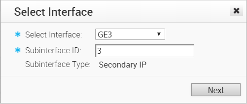
- Click Next.
- In the Secondary IP dialog box, choose your Addressing Type ( DHCP or Static).

- In the Secondary IP dialog box, choose your Addressing Type ( DHCP or Static).
-
Click the Update button.
The Interface column refreshes, showing the newly created Secondary IP (see the Interface Settings image below).

User-defined WAN Overlay Use Cases
The scenarios wherein this configuration is useful are outlined first, followed by a specification of the configuration itself.
- Use Case 1: Two WAN links connected to an L2 Switch – Consider the traditional data center topology where the SD-WAN Edge is connected to an L2 switch in the DMZ that is connected to multiple firewalls, each connected to a different upstream WAN link.
In this topology, the VMware interface has likely been configured with FW1 as the next hop. However, in order to use the DSL link, it must be provisioned with an alternate next hop to which packets should be forwarded, because FW1 cannot reach the DSL. When defining the DSL link, the user must configure a custom next hop IP address as the IP address of FW2 to ensure that packets can reach the DSL modem. Additionally, the user must configure a custom source IP address for this WAN link to allow the edge to identify return interfaces. The final configuration becomes similar to the following figure: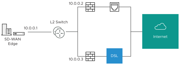
The following paragraph describes how the final configuration is defined.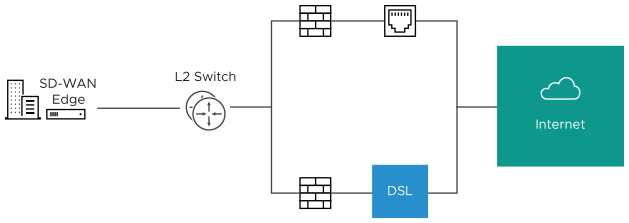
- The interface is defined with IP address 10.0.0.1 and next hop 10.0.0.2. Because more than one WAN link is attached to the interface, the links are set to “user defined.”
- The Cable link is defined and inherits the IP address of 10.0.0.1 and next hop of 10.0.0.2. No changes are required. When a packet needs to be sent out the cable link, it is sourced from 10.0.0.1 and forwarded to the device that responds to ARP for 10.0.0.2 (FW1). Return packets are destined for 10.0.0.1 and identified as having arrived on the cable link.
- The DSL link is defined, and because it is the second WAN link, the SD-WAN Orchestrator flags the IP address and next hop as mandatory configuration items. The user specifies a custom virtual IP (e.g. 10.0.0.4) for the source IP and 10.0.0.3 for the next hop. When a packet needs to be sent out the DSL link, it is sourced from 10.0.0.4 and forwarded to the device that responds to the ARP for 10.0.0.3 (FW2). Return packets are destined for 10.0.0.4 and identified as having arrived on the DSL link.
- Case 2: Two WAN links connected to an L3 switch/router: Alternatively, the upstream device may be an L3 switch or a router. In this case, the next hop device is the same (the switch) for both WAN links, rather than different (the firewalls) in the previous example. Often this is leveraged when the firewall sits on the LAN side of the SD-WAN Edge.
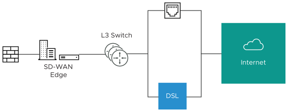
In this topology, policy-based routing will be used to steer packets to the appropriate WAN link. This steering may be performed by the IP address or by the VLAN tag, so we support both options.
Steering by IP: If the L3 device is capable of policy-based routing by source IP address, then both devices may reside on the same VLAN. In this case, the only configuration required is a custom source IP to differentiate the devices.
The following paragraph describes how the final configuration is defined.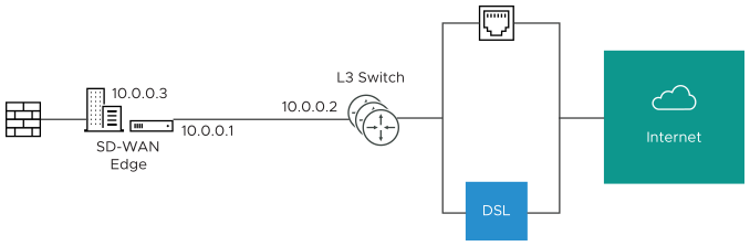
- The interface is defined with IP address 10.0.0.1 and next hop 10.0.0.2. Because more than one WAN link is attached to the interface, the links are set to “user defined.”
- The Cable link is defined and inherits the IP address of 10.0.0.1 and next hop of 10.0.0.2. No changes are required. When a packet needs to be sent out the cable link, it is sourced from 10.0.0.1 and forwarded to the device that responds to ARP for 10.0.0.2 (L3 Switch). Return packets are destined for 10.0.0.1 and identified as having arrived on the cable link.
- The DSL link is defined, and because it is the second WAN link, the SD-WAN Orchestrator flags the IP address and next hop as mandatory configuration items. The user specifies a custom virtual IP (for example, 10.0.0.3) for the source IP and the same 10.0.0.2 for the next hop. When a packet needs to be sent out the DSL link, it is sourced from 10.0.0.3 and forwarded to the device that responds to the ARP for 10.0.0.2 (L3 Switch). Return packets are destined for 10.0.0.3 and identified as having arrived on the DSL link.
Steering by VLAN: If the L3 device is not capable of source routing, or if for some other reason the user chooses to assign separate VLANs to the cable and DSL links, this must be configured.
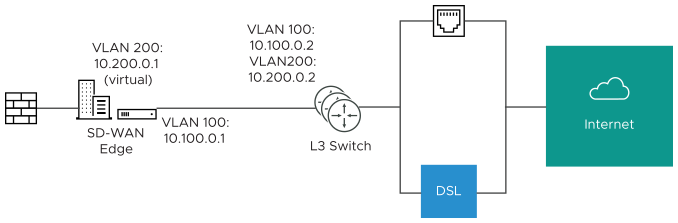
- The interface is defined with IP address 10.100.0.1 and next hop 10.100.0.2 on VLAN 100. Because more than one WAN link is attached to the interface, the links are set to “user defined.”
- The Cable link is defined and inherits VLAN 100 as well as the IP address of 10.100.0.1 and next hop of 10.100.0.2. No changes are required. When a packet needs to be sent out the cable link, it is sourced from 10.100.0.1, tagged with VLAN 100 and forwarded to the device that responds to ARP for 10.100.0.2 on VLAN 100 (L3 Switch). Return packets are destined for 10.100.0.1/VLAN 100 and identified as having arrived on the cable link.
- The DSL link is defined, and because it is the second WAN link the SD-WAN Orchestrator flags the IP address and next hop as mandatory configuration items. The user specifies a custom VLAN ID (200) as well as virtual IP (e.g. 10.200.0.1) for the source IP and the 10.200.0.2 for the next hop. When a packet needs to be sent out the DSL link, it is sourced from 10.200.0.1, tagged with VLAN 200 and forwarded to the device that responds to the ARP for 10.200.0.2 on VLAN 200 (L3 Switch). Return packets are destined for 10.200.0.1/VLAN 200 and identified as having arrived on the DSL link.
- Case 3: One-arm Deployments: One-arm deployments end up being very similar to other L3 deployments.
Again, the SD-WAN Edge shares the same next hop for both WAN links. Policy-based routing can be done to ensure that traffic is forwarded to the appropriate destination as defined above. Alternately, the source IP and VLAN for the WAN link objects in the VMware may be the same as the VLAN of the cable and DSL links to make the routing automatic.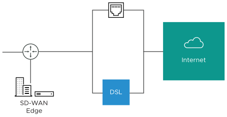
- Case 4: One WAN link reachable over multiple interfaces: Consider the traditional gold site topology where the MPLS is reachable via two alternate paths. In this case, we must define a custom source IP address and next hop that can be shared regardless of which interface is being used to communicate.

- GE1 is defined with IP address 10.10.0.1 and next hop 10.10.0.2
- GE2 is defined with IP address 10.20.0.1 and next hop 10.20.0.2
- The MPLS is defined and set as reachable via either interface. This makes the source IP and next hop IP address mandatory with no defaults.
- The source IP and destination are defined, which can be used for communication irrespective of the interface being used. When a packet needs to be sent out the MPLS link, it is sourced from 169.254.0.1, tagged with the configured VLAN and forwarded to the device that responds to ARP for 169.254.0.2 on the configured VLAN (CE Router). Return packets are destined for 169.254.0.1 and identified as having arrived on the MPLS link.
Note: If OSPF or BGP is not enabled, you may need to configure a transit VLAN that is the same on both switches to enable reachability of this virtual IP.
Interface Configuration
Clicking the Edit link presents a dialog for updating the settings for a specific interface. The following sections provide a short description for the various dialogs that are presented for the Edge model and interface types.
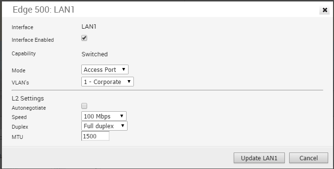
Edge 500 LAN Access
The following shows the parameters for an Edge 500 LAN interface configured as an Access Port. You can choose a VLAN for the port and select L2 Settings for Autonegotiate (selected by default), Speed, Duplex type, and MTU size (default 1500).
Edge 500 LAN Trunk
The following shows the parameters for an Edge 500 LAN interface configured as a Trunk Port. You can choose VLANs for the port, how Untagged VLAN data is handled (routed to a specific VLAN or Dropped) and select L2 Settings for Autonegotiate (selected by default), Speed, Duplex type, and MTU size (default 1500).

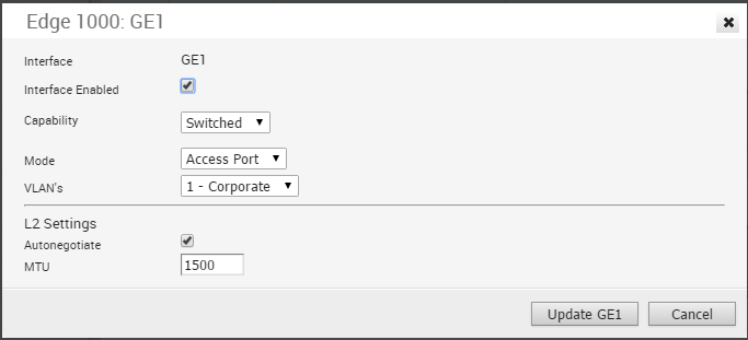
Edge 1000 LAN Access
The following shows the parameters for an Edge 1000 LAN interface configured as a Switched Access Port. You can choose a VLAN for the port and select L2 Settings for Autonegotiate (selected by default), Speed, Duplex type, and MTU size (default 1500).
Edge 1000 LAN Trunk
The following shows the parameters for an Edge 1000 LAN interface configured as a Trunk Port. You can choose VLANs for the port, how Untagged VLAN data is handled (routed to a specific VLAN or Dropped) and select L2 Settings for Autonegotiate (selected by default), Speed, Duplex type, and MTU size (default 1500).

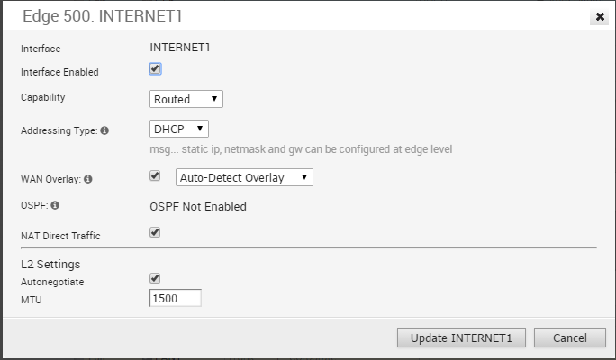
Edge 500 WAN
The following shows the parameters for an Edge 500 WAN interface with Capability= Routed. You can choose Addressing Type (DHCP, PPPoE, or static), a WAN Overlay (Auto-detect or User Defined), enable OSPF, enable NAT Direct Traffic, and select L2 Settings for Autonegotiate (selected by default), Speed, Duplex type, and MTU size (default 1500).
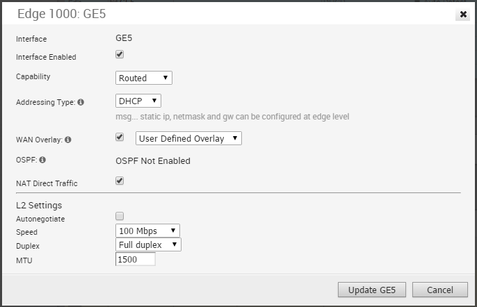
Edge 1000 WAN
The following shows the parameters for an Edge 1000 WAN interface with Capability= Routed. You can choose Addressing Type (DHCP, PPPoE, or static), a WAN Overlay (Auto-detect or User Defined), enable OSPF, enable NAT Direct Traffic, and select L2 Settings for Autonegotiate (selected by default), Speed, Duplex type, and MTU size (default 1500).
Edge 500 WLAN
Initially, two Wi-Fi networks are defined for the SD-WAN Edge 500; one as a Corporate network and one as a Guest network that is initially disabled. Additional wireless networks can be defined, each with a specific VLAN, SSID, and security configuration.

Security for Wi-Fi Connections
Security for your Wi-Fi connections can be one of three types:
| Type | Description |
|---|---|
| Open | No security is enforced. |
| WPA2 / Personal | A password is used to authenticate a user. |
| WPA2 / Enterprise | A Radius server is used to authenticate a user. In this scenario, a Radius Server must be configured in Network Services and the Radius Server must be selected in the Profile Authentication Settings on the Device page. The default settings for Security can also be overridden on the Edge Device page. |
