


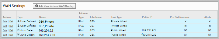
The WAN settings enables you to add or modify a User-Defined WAN Overlay.
- Private Overlay: This is required on a private network where you want to have the Edge build overlay VCMP tunnels directly between private IP addresses assigned to each Edge on the private network.
Note: In a Partner Gateway setup with handoff Interface configured, when an Edge with private Interface has both IPv4 and IPv6 user-defined overlays, the Edge tries to establish IP tunnels towards the public IP address of the Gateway based on the tunnel preference.
- Public Overlay: This is useful when you want to set a custom VLAN or source IP address and Gateway address for the VCMP tunnels, to reach VMware SD-WAN Gateways over the Internet, as determined by the SD-WAN Orchestrator.
You can also modify or delete an existing auto-detected WAN Overlay that has been detected on a routed interface. An auto-detected overlay is available only when the Edge has successfully made a VCMP tunnel over a routed interface configured with WAN Overlay to Gateways designated by the SD-WAN Orchestrator.
Procedure
- Scroll down to WAN Settings.
- In the User Defined WAN Overlay window, choose the Link Type from the following available options:
-
Public overlay is used over the Internet where SD-WAN cloud Gateways, that are on the Internet, are reachable. The user-defined overlay must be attached to an Interface. The public overlay instructs the Edge to assign primary and secondary gateways over the interface it is attached, to help determine the outside global NAT address. This outside global address is reported to the Orchestrator so that all the other Edges use this outside global address, if configured to build VCMP tunnels to the currently selected Edge.
Note: By default, all routed interfaces will attempt to Auto Detect, that is build VCMP tunnels to, pre-assigned cloud Gateways over the Internet. If the attempt is successful, an Auto Detect Public overlay is created. A User Defined Public overlay is only needed if your Internet service requires a VLAN tag or you want to use a different public IP address from the one that the Edge has learned through DHCP on the public facing interface. - Private overlay is used on private networks such as an MPLS network or point-to-point link. A private overlay is attached to an interface like any user defined overlay and assumes that the IP address on the interface it is attached is routable for all other Edges on the same private network. This means that there is no NAT on the WAN side of the interface. When you attach a private overlay to an interface, the Edge advises the Orchestrator that the IP address on the interface should be used for any remote Edges configured to build tunnels to it.
The following tables describe the Overlay settings:Table 1. Settings common for Public and Private Overlay Option Description Address Type Select the IP address type from the drop-down list. You can choose the WAN overlay link to use either IPv4 or IPv6 address. In the new Orchestrator UI, you can configure the WAN overlay link to use both IPv4 and IPv6 addresses. See Configure Edge WAN Overlay Settings with New Orchestrator UI.
Note: When you choose IPv6 address, the Duplicate Address Detection (DAD) is not supported for IP steered overlay. The overlay network is steered when you configure the source IP address in the Optional Configuration.Name Enter a descriptive WAN overlay name for the public or private link. Note: WAN overlay name should only consist of ASCII characters. Non-ASCII characters are not supported.You can reference this name while choosing a WAN link in a Business Policy. See Configure Link Steering Modes.Pre-Notification Alerts Sends alerts related to the Overlay network to the Operator. Ensure that you have enabled the Link alerts in the page to receive the alerts. Alerts Sends alerts related to the Overlay network to the Customer. Ensure that you have enabled the Link alerts in the page to receive the alerts. Select Interfaces The Routed Interfaces enabled with IPv4 WAN Overlay or IPv6 WAN Overlay and set to User Defined Overlay are displayed as checkboxes. The Interfaces displayed are based on the selected Address Type. Select one or more routed interfaces and the current user-defined overlay is attached to the selected interface.
Note: For the 610-LTE, you can add User Defined WAN overlay on CELL1 or CELL2. The SD-WAN Orchestrator will display both CELL1 and CELL2, irrespective of SIM presence. Therefore, you must be aware of which SIM slot is enabled (Active) and choose that SIM.Table 2. Public Overlay Settings Option Description Public IP Address Displays the discovered public IP address for a public Overlay. This field is populated once the outside global NAT address is discovered using the Gateway method. The following image shows an example of Settings for Public Overlay: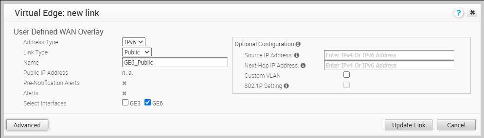
Table 3. Private Overlay Settings Option Description SD-WAN Service Reachable When creating a private overlay and attaching it to a private WAN like MPLS network, you may also be able to reach the internet over the same WAN, usually through a firewall in the data center. In this case, it is recommended to enable SD-WAN Service Reachable as it provides the following:
- A secondary path to the internet for access to internet hosted SD-WAN Gateways. This is used if all the direct links to the internet from this Edge fail.
- A secondary path to the Orchestrator, when all the direct links to the internet from this Edge fail. The management IP address the Edge uses to communicate must be routable within MPLS, otherwise NAT Direct would need to be checked on the private interface for the Orchestrator traffic to come back properly.
Note: The SD-WAN Edge always prefers the VCMP tunnel created over a local internet link (short path), compared to the VCMP tunnel created over the private network using a remote firewall to the internet (long path).Note: Per-packet or round-robin load balancing will not be performed between the short and long paths.In a site with no direct public internet access, the SD-WAN Service Reachable option allows the private WAN to be used for private site-to-site VCMP tunnels and as a path to communicate with an internet hosted VMware SD-WAN service.
Public SD-WAN Addresses When you select the SD-WAN Service Reachable checkbox, a list of public IPv4 and IPv6 addresses of SD-WAN Gateways and SD-WAN Orchestrator is displayed, which may need to be advertised across the private network, if a default route has not been already advertised across the same private network from the firewall.
Note: Some IP addresses in the list, such as Gateways, may change over time.The following image shows an example of Settings for Private Overlay: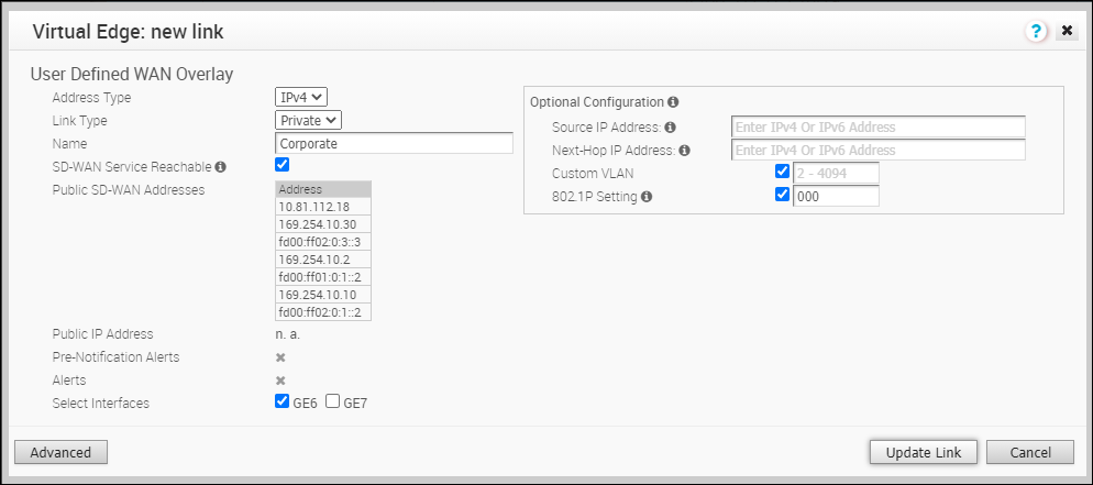
Table 4. Optional Configuration Option Description Source IP Address This is the raw socket source IP address used for VCMP tunnel packets that originate from the interface to which the current overlay is attached.
Source IP address does not have to be pre-configured anywhere but must be routable to and from the selected interface.
You can enter IPv4 or IPv6 address to establish WAN overlay with the peer.
Next-Hop IP Address Enter the next hop IP address to which the packets, which come from the raw socket source IP address specified in the Source IP Address field, are to be routed.
You can enter IPv4 or IPv6 address.
Custom VLAN Select the checkbox to enable custom VLAN and enter the VLAN ID. The range is 2 to 4094.
This option applies the VLAN tag to the packets originated from the Source IP Address of a VCMP tunnel from the interface to which the current overlay is attached.
802.1P Setting Sets 802.1p PCP bits on frames leaving the interface to which the current overlay is attached. This setting is only available for a specific VLAN. PCP priority values are a 3-digit binary number. The range is from 000 to 111 and default is 000.
This checkbox is available only when the system property session.options.enable8021PConfiguration must be set to True. By default, this value is False.
If this option is not available for you, contact the VMware support of your operations team to enable the setting.
Click Advanced to configure the following settings:
Table 5. Advanced Settings common for Public and Private Overlay Option Description Bandwidth Measurement Choose a method to measure the bandwidth from the following options: - Measure Bandwidth (Slow Start): When measuring the default bandwidth reports incorrect results, it may be due to ISP throttling. To overcome this behavior, choose this option for a sustained slow burst of UDP traffic followed by a larger burst.
- Measure Bandwidth (Burst Mode): Choose this option to perform short bursts of UDP traffic to an SD-WAN Gateway for public links or to the peer for private links, to assess the bandwidth of the link.
- Do Not Measure (define manually): Choose this option to configure the bandwidth manually. This is recommended for the Hub sites because:
- Hub sites can usually only measure against remote branches which have slower links than the hub.
- If a hub Edge fails and is using a dynamic bandwidth measurement mode, it may add delay in the hub Edge coming back online while it re-measures the available bandwidth.
Upstream Bandwidth Enter the upstream bandwidth in Mbps. This option is available only when you choose Do Not Measure (define manually). Downstream Bandwidth Enter the downstream bandwidth in Mbps. This option is available only when you choose Do Not Measure (define manually). Dynamic Bandwidth Adjustment Dynamic Bandwidth Adjustment attempts to dynamically adjust the available link bandwidth based on packet loss and intended for use with Wireless broadband services where bandwidth can suddenly decrease.
Note: This configuration is not recommended for Edges with software release 3.3.x or earlier. You can configure this option for Edges with release 3.4 or later.Note: This configuration is not supported with public link CoS.Link Mode Select the mode of the WAN link from the drop-down. The following options are available: - Active: This option is selected by default. The interface is used as a primary mode to send traffic.
- Backup: This option puts the interface that this WAN Overlay is attached to into Backup Mode. This means that the management tunnels are torn down for this interface, and the attached WAN link receives no data traffic. The Backup link would only be used if all paths from a number of Active links go down, which also drops the number of Active links below the number of Minimum Active Links configured. When this condition is met, management tunnels would be rebuilt for the interface and the Backup Link would become Active and pass traffic.
Only one interface on an Edge can be put into backup mode. When enabled, the interface will be displayed in page as Cloud Status: Standby.
Note: Use this option to reduce user data and SD-WAN performance measurement bandwidth consumption on a 4G or LTE service. However, failover times will be slower when compared to a link that is configured as either Hot Standby or as Active and uses a business policy to regulate bandwidth consumption. Do not use this feature if the Edge is configured as a Hub or is part of a Cluster. - Hot Standby: When you configure the WAN link for Hot Standby mode, the management tunnels are built, which enables a rapid switchover in case of a failure. The Hot Standby link receives no data traffic except for heartbeats, which are sent every 5 seconds.
When all paths from a number of Active links go down, which also drops the number of Active links below the number of Minimum Active Links configured, the Hot Standby link would come up. The traffic is sent through the Hot Standby path.
When the path to the Primary Gateway comes up on Active links such that the number of Active links exceeds the number of Minimum Active Links configured, the Hot Standby link returns to Standby mode and the traffic flow switches over to the Active link(s).
For more information, see Configure Hot Standby Link.
Once you activate the Backup or Hot Standby link option on an Interface, you cannot configure additional Interfaces of that Edge as either a Backup or Hot Standby Link, as an Edge can have only one WAN link as a Backup or Hot Standby at a time.
Minimum Active Links This option is available only when you choose Backup or Hot Standby as Link Mode. Select the number of active links that can be present in the network at a time, from the drop-down list. When the number of current active links that are UP goes below the selected number, then the Backup or the Hot Standby link comes up. The range is 1 to 3, with the default being 1. MTU The SD-WAN Edge performs path MTU discovery and the discovered MTU value is updated in this field. Most wired networks support 1500 Bytes while 4G networks supporting VoLTE typically only allow up to 1358 Bytes.
It is not recommended to set the MTU below 1300 Bytes as it may introduce framing overhead. There is no need to set MTU unless path MTU discovery has failed.
You can find if the MTU is large from the page, as the VCMP tunnels (paths) for the interface never become stable and repeatedly reach an UNUSABLE state with greater than 25% packet loss.
As the MTU slowly increases during bandwidth testing on each path, if the configured MTU is greater than the network MTU, all packets greater than the network MTU are dropped, causing severe packet loss on the path.
For more information, see Tunnel Overview and MTU .
Overhead Bytes Enter a value for the Overhead bandwidth in bytes. This is an option to indicate the additional L2 framing overhead that exists in the WAN path.
When you configure the Overhead Bytes, the bytes are additionally accounted for by the QoS schedular for each packet, in addition to the actual packet length. This ensures that the link bandwidth is not oversubscribed due to any upstream L2-framing overhead.
Path MTU Discovery Select the checkbox to enable the discovery of Path MTU. After determining the Overhead bandwidth to be applied, the Edge performs Path MTU Discovery to find the maximum permissible MTU to calculate the effective MTU for customer packets. For more information, see Tunnel Overhead and MTU. Configure Class of Service SD-WAN Edges can prioritize traffic and provide a 3x3 QoS class matrix over both Internet and Private networks alike. However, some public or private (MPLS) networks include their own quality of service (QoS) classes, each with specific characteristics such as rate guarantees, rate limits, packet loss probability etc.
This option allows the Edge to understand the public or private network QoS bandwidth available and policing for the public or private Overlay on a specific interface.
Note: Outer DSCP tags must be set in business policy per application/rule and in this feature, each Class of Service line is matching on those DSCP tags set in the business policy.After you select this checkbox, configure the following:
- Class of Service: Enter a descriptive name for the class of service. You can reference this name while choosing a WAN link in a Business Policy. See Configure Link Steering Modes.
- DSCP Tags: Class of service will match on the DSCP tags defined here. DSCP tags are assigned to each application using business policy.
- Bandwidth: Percentage of interface transmit/upload bandwidth available for this class as determined by the public or private network QoS class bandwidth guaranteed.
- Policing: This option monitors the bandwidth used by the traffic flow in the class of service and when the traffic exceeds the bandwidth, it rate-limits the traffic.
- Default Class: If the traffic does not fall under any of the defined classes, the traffic is associated with the default CoS.
Note: The Dynamic Bandwidth Adjustment configuration is not supported with public link CoS.For more information about how to configure CoS, see Configure Class of Service.
Strict IP precedence This checkbox is available when you select the Configure Class of Service checkbox.
When you enable this option, 8 VCMP sub-paths corresponding to the 8 IP precedence bits are created. Use this option when you want to combine the Classes of Service into less number of classes in the network of your Service Provider.
By default, this option is deactivated and the VCMP sub-paths are created for the exact number of classes of service that are configured. The grouping is not applied.
Table 6. Advanced Settings for Public Overlay Option Description UDP Hole Punching If a Branch to Branch SD-WAN overlay is required and branch Edges are deployed behind NAT devices, that is NAT device is WAN side of the Edge, the direct VCMP tunnel on UDP/2426 will not likely come up if the NAT devices have not been configured to allow incoming VCMP tunnels on UDP port 2426 from other Edges.
Use Branch to Branch VPN to enable branch to branch tunnels. See Configure a Tunnel Between a Branch and a Branch VPN and Configure Cloud VPN and Tunnel Parameters at the Edge level.
Use to check that one Edge has built a tunnel to another Edge.
UDP hole punching attempts to work around NAT devices blocking incoming connections. However, this technique is not applicable in all scenarios or with all types of NATs, as NAT operating characteristics are not standardized.
Enabling UDP hole punching on an Edge overlay interface, instructs all remote Edges to use the discovered NAT public IP and NAT dynamic source port discovered through SD-WAN Gateway as destination IP and destination port for creating a VCMP tunnel to this Edge overlay interface.
Note: Before enabling UDP hole punching, configure the branch NAT device to allow UDP/2426 inbound with port forwarding to the Edge private IP address or put the NAT device, which is usually a router or modem, into bridge mode. Use UDP hole punching only as a last resort as it will not work with firewalls, symmetric NAT devices, 4G/LTE networks due to CGNAT, and most modern NAT devices.UDP hole punching may introduce additional connectivity issues as remote sites try to use the new UDP dynamic port for VCMP tunnels.
Type When configuring a business policy for an Edge, you can choose the Link Steering to prefer a Transport Group as: Public Wired, Public Wireless or Private Wired. See Configure Link Steering Modes.
Choose Wired or Wireless, to put the overlay into a public wired or wireless transport group.
The following image shows Advanced settings for a Public Overlay: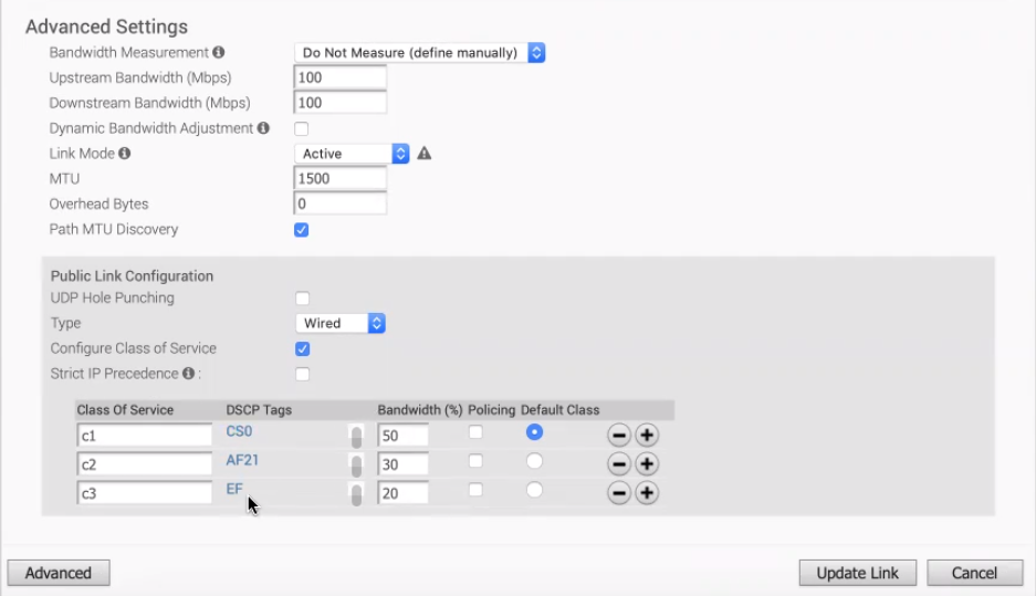
Table 7. Advanced Settings for Private Overlay Option Description Private Network Name If you have more than one private network and want to differentiate between them to ensure that the Edges try to tunnel only to Edges on the same private network then define a Private Network Name and attach the Overlay to it. This prevents tunneling to Edges on a different private network they cannot reach. In addition, configure the Edges in other locations on this private network to use the same private network name.
For example:
Edge1 GE1 is attached to private network A. Use private network A for the private overlay attached to GE1.
Edge1 GE2 is attached to private network B. Use private network B for the private overlay attached to GE2.
Repeat the same attachment and naming for Edge2.
When you enable branch to branch or when Edge2 is a hub site:- Edge1 GE1 attempts to connect to Edge2 GE1 and not GE2.
- Edge1 GE2 attempts to connect to Edge2 GE2 and not GE1.
Configure Static SLA Forces the overlay to assume that the SLA parameters being set are the actual SLA values for the path. No dynamic measurement of packet loss, latency or jitter will be done on this overlay. The QoE report use these values for its Green/Yellow/Red coloring against thresholds. Note:Static SLA configuration is not supported from release 3.4. It is recommended not to use this option, as dynamic measurement of packet loss, latency and jitter will provide a better outcome.
The following image shows Advanced settings for a Private Overlay: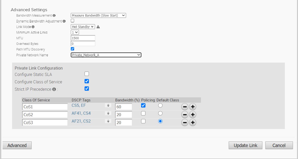
-
