


The xDSL SFP module can be plugged into either the SD-WAN Edge 610 or the SD-WAN Edge 610-LTE device SFP slot and used in ADSL2+/VDSL2 mode. This module must be procured by the user.
Note: Configuring DSL is only available for the 610, 610-LTE, 620, 640, and 680 devices.
Configuring SFP
Click the SFP interface that the specific DSL module is plugged into. When the SFP is plugged in, the slot name is displayed as SFP1 and SFP2.

To Configure SFP:
- Click the Edit link in the Actions column.
The Interface SFP1 dialog for the selected SD-WAN Edge device is displayed.Note: The following steps describe only the SFP configuration. For a description of the other fields in the selected SD-WAN Edge device, see section Configure Interface Settings.

- To configure DSL Settings, select the Override Interface check box.
- Select the Interface Enabled check box.
- In the SFP Settings area, there are two options available from the drop-down list, Standard and DSL. Choose DSL as the SFP Module.
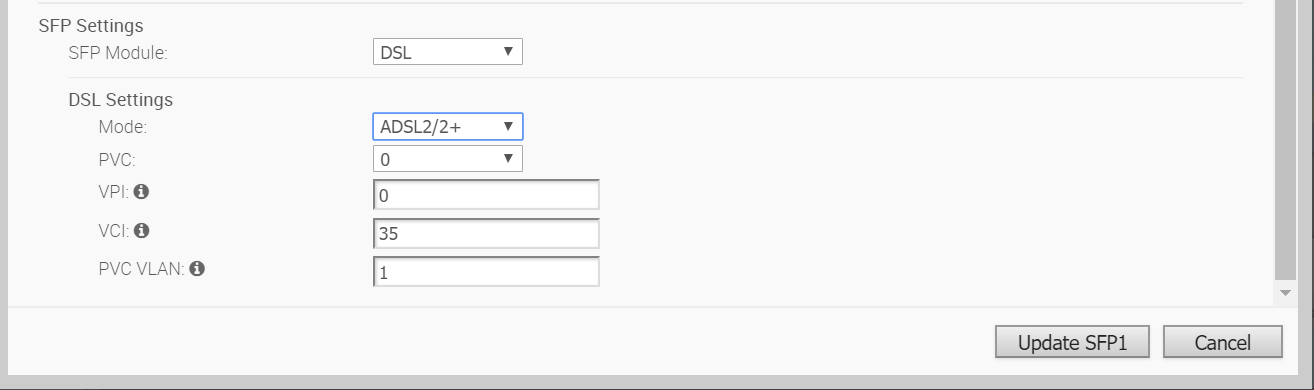
- In the DSL Settings area, configure the following:
Option Description SFP Module By default, Standard is selected. You can select DSL as the module to use the SFP port with higher bandwidth services. DSL Settings The option to configure Digital Subscriber Line (DSL) settings is available when you select the SFP module as DSL. DSL Mode: VDSL2 This option is selected by default. Very-high-bit-rate digital subscriber line (VDSL) technology provides faster data transmission. The VDSL lines connect service provider networks and customer sites to provide high bandwidth applications over a single connection. When you choose VDSL2, select the Profile from the drop-down list. Profile is a list of pre-configured VDSL2 settings. The following profiles are supported: 17a and 30a.
DSL Mode: ADSL2/2+ Asymmetric digital subscriber line (ADSL) technology is part of the xDSL family and is used to transport high-bandwidth data. ADSL2 improves the data rate and reach performance, diagnostics, standby mode, and interoperability of ADSL modems. ADSL2+ doubles the possible downstream data bandwidth. If you choose ADSL2/2+, configure the following settings:
- PVC – A permanent virtual circuit (PVC) is a software-defined logical connection in a network such as a frame relay network. Choose a PVC number from the drop-down list. The range is from 0 to 7.
- VPI – Virtual Path Identifier (VPI) is used to identify the path to route the packet of information. Enter the VPI number, ranging from 0 to 255.
- VCI – Virtual Channel Identifier (VCI) defines the fixed channel on which the packet of information should be sent. Enter the VCI number, ranging from 35 to 65535.
- PVC VLAN – Set up a VLAN to run over PVCs on the ATM module. Enter the VLAN ID, ranging from 1 to 4094.
Note: The 4.3 release introduces four new parameters for PVC VLAN as described below. Click the arrow next to the PVC VLAN text box to display these settings.
- VLAN TX: Upstream VLAN tagging ID. Supported values are 1-4094.
- VLAN RX: Downstream VLAN tagging ID, supported values are 1-4094.
- VLAN TX OP: Operation to perform the upstream PVC VLAN. Supported values are 0-2.
- VLAN RX OP: Operation to perform for the downstream PVC VLAN, supported values are 0-2.
- Click Update SFP1 to save the configuration.
