


You can configure the Interface settings for each Edge model. Each Interface on an Edge can be a Switch Port (LAN) or a Routed (WAN) Interface.
The Interface Settings options vary based on the Edge model. For more information on different Edge models and deployments, see Configure Device Settings.
Procedure
- Scroll down to the Device Settings section, which displays the existing Edge models in the Enterprise.
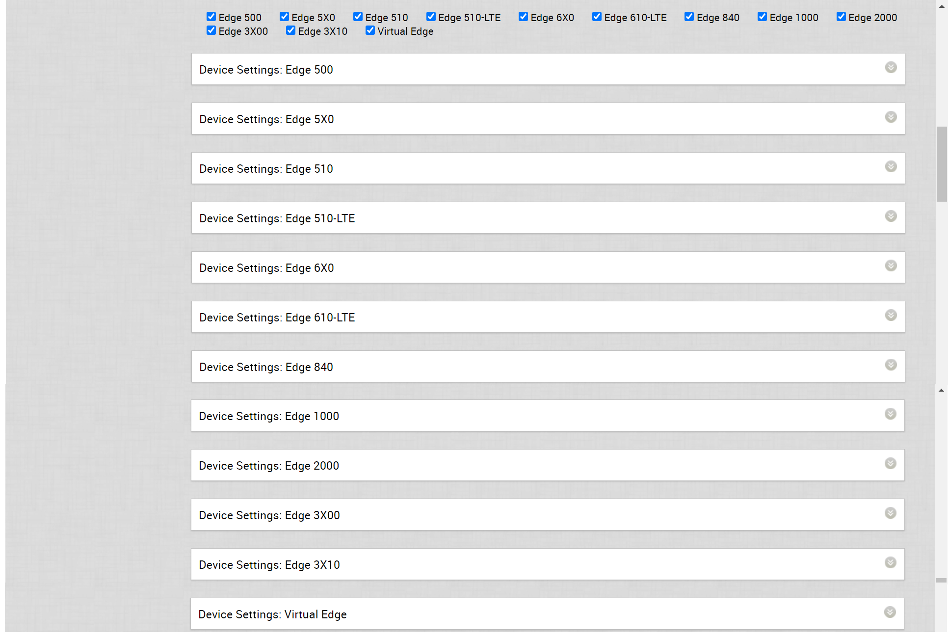
- Click the DOWN arrow next to an Edge model to view the Interface Settings for the Edge.
 The Interface Settings section displays the existing interfaces available in the selected Edge model.
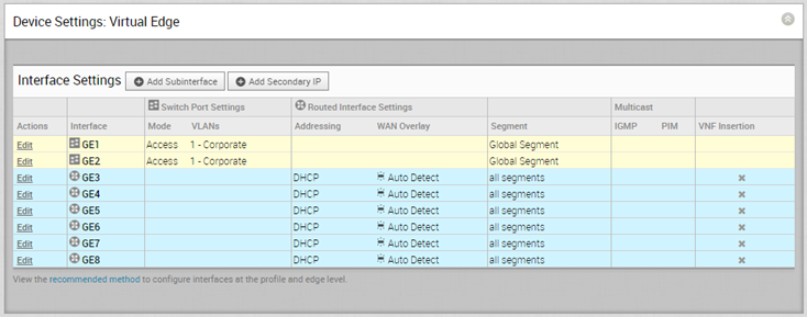
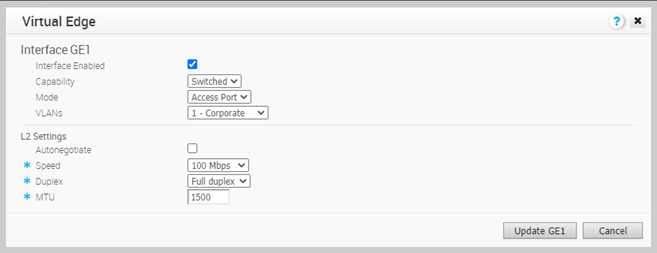
 - The following image shows the Switch Port settings of an Interface.
 You can modify the existing settings as follows:
Option Description Interface Enabled This option is activated by default. If required, you can deactivate the Interface. When deactivated, the Interface is not available for any communication. Capability For a Switch Port, the option Switched is selected by default. You can choose to convert the port to a routed Interface by selecting the option Routed from the drop-down list. Mode Select the mode of the port as Access or Trunk port. VLANs For an Access port, select an existing VLAN from the drop-down list. For a Trunk port, you can select multiple VLANs and select an untagged VLAN.
L2 Settings Autonegotiate This option is activated by default. When activated, Auto negotiation allows the port to communicate with the device on the other end of the link to determine the optimal duplex mode and speed for the connection. Speed This option is available only when Autonegotiate is deactivated. Select the speed that the port has to communicate with other links. By default, 100 Mbps is selected. Duplex This option is available only when Autonegotiate is deactivated. Select the mode of the connection as Full duplex or Half duplex. By default, Full duplex is selected. MTU The default MTU size for frames received and sent on all switch interfaces is 1500 bytes. You can change the MTU size for an Interface. Click Update to save the settings. - The following image shows the Routed Interface settings.
 You can modify the existing settings as follows:
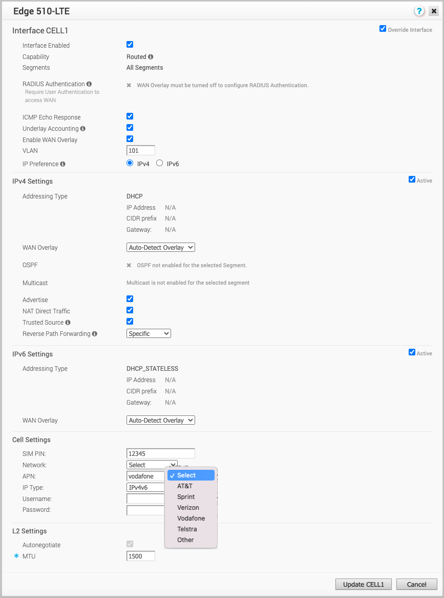
Option Description Interface Enabled This option is enabled by default. If required, you can deactivate the Interface. When deactivated, the Interface is not available for any communication. Capability For a Routed Interface, the option Routed is selected by default. You can choose to convert the Interface to a Switch Port by selecting the option Switched from the drop-down list. Segments By default, the configuration settings are applicable to all the segments. RADIUS Authentication You must turn off WAN Overlay to configure RADIUS Authentication. Select the check box to enable RADIUS Authentication on the Interface and add the MAC addresses that should not be forwarded to RADIUS for re-authentication. For more information, see Enable RADIUS on a Routed Interface. ICMP Echo Response Select the check box to enable the Interface to respond to ICMP echo messages. You can turn off this option for the Interface, for security purposes. Underlay Accounting This option is enabled by default. If a private WAN overlay is defined on the Interface, all underlay traffic traversing the interface will be counted against the measured rate of the WAN link to prevent over-subscription. If you do not want this behavior (for example, while using one-arm deployments), turn off the option. Note: Underlay Accounting is supported for both the IPv4 and IPv6 addresses.Enable WAN Overlay Select the check box to enable WAN overlay for the Interface. VLAN Enter a VLAN ID for the Interface to support VLAN tagging over the port. IP Preference Choose whether the WAN Overlay link should be using IPv4 or IPv6 address when initiating tunnels. This option is available only when you activate both the IPv4 and IPv6 settings. Select the Active check box next to the IP settings to activate the corresponding IP address. IPv4 Settings – Select the Active check box to enable IPv4 Settings. Addressing Type By default, DHCP is selected, which assigns an IPv4 address dynamically. If you select Static or PPPoE, you should configure the addressing details for each Edge. WAN Overlay By default, this option is enabled with Auto-Detect Overlay. You can choose the User Defined Overlay and configure the Overlay settings. For more information, see Configure Edge WAN Overlay Settings. Note: If you have a CSS GRE tunnel created for an Edge and if you change the WAN Overlay settings of the WAN link associated with the CSS tunnel interface from "Auto-Detect Overlay" to "User-Defined Overlay", the WAN link and the associated CSS tunnels will also be removed from the CSS configuration at the Edge level.OSPF This option is enabled only when you have configured OSPF for the Profile. Select the check box and choose an OSPF from the drop-down list. Click toggle advance ospf settings to configure the Interface settings for the selected OSPF. For more information on OSPF settings, see Enable OSPF. Multicast This option is enabled only when you have configured multicast settings for the Profile. You can configure the following multicast settings for the selected Interface. - IGMP - Select the check box to enable Internet Group Management Protocol (IGMP) and only IGMP v2 is supported.
- PIM – Select the check box to enable Protocol Independent Multicast and only PIM Sparse Mode (PIM-SM) is supported.
Click toggle advanced multicast settings to configure the following timers:- PIM Hello Timer – The time interval at which a PIM Interface sends out Hello messages to discover PIM neighbors. The range is from 1 to 180 seconds and the default value is 30 seconds.
- IGMP Host Query Interval – The time interval at which the IGMP querier sends out host-query messages to discover the multicast groups with members, on the attached network. The range is from 1 to 1800 seconds and the default value is 125 seconds.
- IGMP Max Query Response Value – The maximum time that the host has to respond to an IGMP query. The range is from 10 to 250 deciseconds and the default value is 100 deciseconds.
Note: Currently, Multicast Listener Discovery (MLD) is deactivated. Hence, Edge will not be sending multicast listener report when IPv6 address is assigned to Interface. If there is a snooping switch in the network then not sending MLD report may result in Edge not receiving multicast packets which are used in Duplicate Address Detection (DAD). This would result in DAD success even with duplicate address.VNF Insertion You must turn off WAN Overlay and enable Trusted Source to allow VNF insertion. When you insert the VNF into Layer 3 interfaces or sub-interfaces, the system redirects traffic from the Layer 3 interfaces or subinterfaces to the VNF. Advertise Select the check box to advertise the Interface to other branches in network. NAT Direct Traffic Select the check box to apply NAT for IPv4 to network traffic sent from the Interface. Trusted Source Select the check box to set the Interface as a trusted source. Reverse Path Forwarding You can choose an option for Reverse Path Forwarding (RPF) only when you have enabled Trusted Source. This option allows traffic on the interface only if return traffic can be forwarded on the same interface. This helps to prevent traffic from unknown sources like malicious traffic on an enterprise network. If the incoming source is unknown, then the packet is dropped at ingress without creating flows. Select one of the following options from the drop-down list: - Not Enabled – Allows incoming traffic even if there is no matching route in the route table.
- Specific – This option is selected by default, even when the Trusted Source option is not enabled. The incoming traffic should match a specific return route on the incoming interface. If a specific match is not found, then the incoming packet is dropped. This is a commonly used mode on interfaces configured with public overlays and NAT.
- Loose – The incoming traffic should match any route(Connected/Static/Routed) in the routing table. This allows asymmetrical routing and is commonly used on interfaces that are configured without next hop.
IPv6 Settings – Select the Active check box to enable IPv6 Settings. Addressing Type Choose one of the options from the following to assign an IPv6 address dynamically. - DHCP Stateless – Allows the Interface to self-configure the IPv6 address. It is not necessary to have a DHCPv6 server available at the ISP and an ICMPv6 discover message will originate from the Edge and is used for auto-configuration.
Note: In DHCP Stateless configuration, two IPv6 addresses are created at the Kernel Interface level. The Edge does not use the host address which matches the Link local address.
- DHCP Stateful – This option is similar to DHCP for IPv4. The Gateway connects to the DHCPv6 server of the ISP for a leased address and the server maintains the status of the IPv6 address.
Note: In stateful DHCP, when the valid lifetime and preferred lifetime are set with the infinite value (0xffffffff(4294967295)), the timer does not work properly. The maximum value that the valid and preferred timers can hold is 2147483647.
- Static – If you select this option, you should configure the addressing details for each Edge.
Note: For Cell Interfaces, the Addressing Type would be Static by default.WAN Overlay By default, this option is enabled with Auto-Detect Overlay. You can choose the User Defined Overlay and configure the Overlay settings. For more information, see Configure Edge WAN Overlay Settings. Advertise Select the check box to advertise the Interface to other branches in network. NAT Direct Traffic Select the check box to apply NAT for IPv6 to network traffic sent from the Interface. Trusted Source Select the check box to set the Interface as a trusted source. Reverse Path Forwarding You can choose an option for Reverse Path Forwarding (RPF) only when you have enabled Trusted Source. This option allows traffic on the interface only if return traffic can be forwarded on the same interface. This helps to prevent traffic from unknown sources like malicious traffic on an enterprise network. If the incoming source is unknown, then the packet is dropped at ingress without creating flows. Select one of the following options from the drop-down list: - Not Enabled – Allows incoming traffic even if there is no matching route in the route table.
- Specific – This option is selected by default, even when the Trusted Source option is not enabled. The incoming traffic should match a specific return route on the incoming interface. If a specific match is not found, then the incoming packet is dropped. This is a commonly used mode on interfaces configured with public overlays and NAT.
- Loose – The incoming traffic should match any route(Connected/Static/Routed) in the routing table. This allows asymmetrical routing and is commonly used on interfaces that are configured without next hop.
L2 Settings Autonegotiate This option is enabled by default. When enabled, Auto negotiation allows the port to communicate with the device on the other end of the link to determine the optimal duplex mode and speed for the connection. Speed This option is available only when Autonegotiate is not enabled. Select the speed that the port has to communicate with other links. By default, 100 Mbps is selected. Duplex This option is available only when Autonegotiate is not enabled. Select the mode of the connection as Full duplex or Half duplex. By default, Full duplex is selected. MTU The default MTU size for frames received and sent on all routed interfaces is 1500 bytes. You can change the MTU size for an Interface. Enable LoS Detection This option is available only for a routed Interface of an Edge. Select the check box to enable Loss of Signal (LoS) detection by using ARP monitoring. For more information, see HA LoS Detection on Routed Interfaces.
Note: You can select the check box only when you have enabled High Availability on the Edge.ARP Polling Interval This option is available only when Enable LoS Detection is enabled. Select the ARP Interval. The available options are 1, 3, 5, 10 seconds and the default value is 3 seconds. The LoS is detected on the Interface based on the probe interval. When the Interface does not receive 3 consecutive ARP responses, then the Interface is considered to be down by LoS. Cell Settings – This cellular related configuration option is available only for Edge models that support cellular connectivity, such as Edge 510-LTE and Edge 610-LTE. SIM PIN Enter the PIN number used to unlock the SIM card. Network Select the Network of the Cell from the drop-down list. The following options are available: AT&T, Sprint, Verizon, Vodafone, Telstra, and Other. APN Name of optional carrier specific Access point. IP Type Select the type of IP address to be assigned to the Interface, as IPv4 or IPv6. Username Optional username provided by the carrier. Password Optional password provided by carrier. SFP Settings – This option is available only for Edge models that support SFP ports. SFP Module By default, Standard is selected. You can select DSL or GPON as the module to use the SFP port with higher bandwidth services. DSL Settings – The option to configure Digital Subscriber Line (DSL) settings is available when you select the SFP module as DSL. Mode Choose the DSL mode from the following options: - VDSL2 – This option is selected by default. Very-high-bit-rate digital subscriber line (VDSL) technology provides faster data transmission. The VDSL lines connect service provider networks and customer sites to provide high bandwidth applications over a single connection.
When you choose VDSL2, select the Profile from the drop-down list. Profile is a list of pre-configured VDSL2 settings. The following profiles are supported: 17a and 30a.
- ADSL2/2+ – Asymmetric digital subscriber line (ADSL) technology is part of the xDSL family and is used to transport high-bandwidth data. ADSL2 improves the data rate and reach performance, diagnostics, standby mode, and interoperability of ADSL modems. ADSL2+ doubles the possible downstream data bandwidth.
If you choose ADSL2/2+, configure the following settings:
- PVC – A permanent virtual circuit (PVC) is a software-defined logical connection in a network such as a frame relay network. Choose a PVC number from the drop-down list. The range is from 0 to 7.
- VPI – Virtual Path Identifier (VPI) is used to identify the path to route the packet of information. Enter the VPI number, ranging from 0 to 255.
- VCI – Virtual Channel Identifier (VCI) defines the fixed channel on which the packet of information should be sent. Enter the VCI number, ranging from 35 to 65535.
- PVC VLAN – Set up a VLAN to run over PVCs on the ATM module. Enter the VLAN ID, ranging from 1 to 4094.
GPON Settings – The option to configure Gigabit Passive Optical Network (GPON) settings is available when you select the SFP module as GPON. GPON Settings Configure the GPON mode settings: - Subscriber Location ID Mode – Choose the mode of the Subscriber Location ID from the following options:
- ASCII – Allows up to 10 ASCII characters.
- HEX – Allows up to 20 Hexadecimal characters.
- Subscriber Location ID – Enter the location ID according to the selected mode.
If you are using USB Modem to connect to the network, to enable IPv6 addressing, configure the following manually in the Edge:- Add the global parameter
“usb_tun_overlay_pref_v6”:1to/etc/config/edged, to update the preference to IPv6 address. - Run the following command to update the IP type of the Interface to IPv6.
/etc/modems/modem_apn.sh [USB] [ACTION] [ACTION ARGS...]
Enter the parameters as follows:
- USB – Enter the USB Number
- Enter the APN settings as follows:
- apn – Enter the Access Point Name.
- username – Enter the username provided by the carrier.
- password – Enter the password provided by the carrier.
- spnetwork – Enter the name of the Service Provider Network.
- simpin – Enter the PIN number used to unlock the SIM card.
- auth – Specify the Authentication type.
- iptype – Enter the type of IP address.
The following is an example command with sample parameters:
/etc/modems/modem_apn.sh USB3 set ‘’vzwinternet’' ‘’ ‘VERIZON’ ‘’ ‘’ ‘ipv4v6’
Note: VMware SD-WAN supports only Inseego skyus DS2 modems. - Some of the Edge models support Wireless LAN. The following image shows WLAN Interface settings.
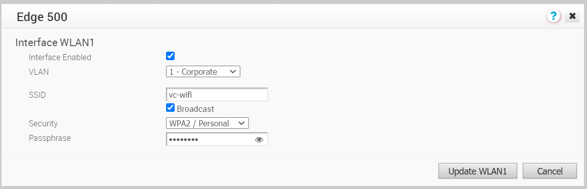 You can modify the settings as follows:
Option Description Interface Enabled This option is enabled by default. If required, you can deactivate the Interface. When deactivated, the Interface is not available for any communication. VLAN Choose the VLAN to be used by the Interface. SSID Enter the wireless network name. Select the Broadcast check box to broadcast the SSID name to the surrounding devices.
Security Select the type of security for the Wi-Fi connection, from the drop-down list. The following options are available: - Open – No security is enforced.
- WPA2 / Personal – A password is required for authentication. Enter the password in the Passphrase field.
- WPA2 / Enterprise – A RADIUS server is used for authentication. You should have already configured a RADIUS server and selected it for the Profile and Edge.
To configure a RADIUS server, see Configure Authentication Services.
To select the RADIUS server for a Profile, see Configure Authentication Settings.
- You can add Sub Interfaces to an existing Interface.
- In the Interface Settings section, click Add Sub Interface.
- In the Select Interface window, select the Interface for which you want to add a Sub Interface.
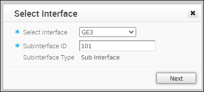 Enter the Subinterface ID and click Next.
 - In the Sub Interface window, configure the Interface settings.
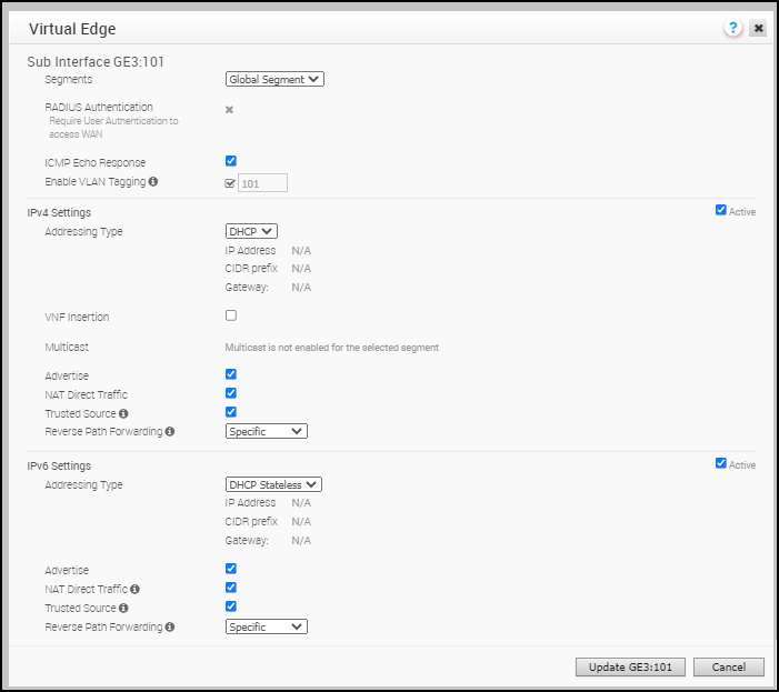 Note: For more information on the configuration options, refer to the Routed Interface settings explained in Step 7. However, for a Sub Interface, you must select a segment from the drop-down menu. In a Routed Interface, the configuration settings are applied to all the segments by default.
- You can add Secondary IP addresses to an existing Interface.
- In the Interface Settings section, click Add Secondary IP.
- In the Select Interface window, select the Interface for which you want to add a secondary IP address.
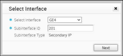 Enter the Subinterface ID and click Next.
 - In the Secondary IP window, configure the Interface settings.
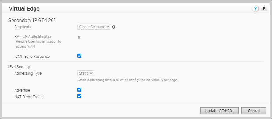 For more information on the configuration options, refer to the Routed Interface settings explained in Step 7.
What to do next
When you configure the Interface Settings for a Profile, the settings are automatically applied to the Edges that are associated with the profile. If required, you can override the configuration for a specific Edge as follows:
- In the Enterprise portal, click .
- Click the Device Icon next to an Edge, or click the link to an Edge and then click the Device tab.
- In the Device tab, scroll down to the Interface Settings section, which displays the interfaces available in the selected Edge.
- Click the Edit option for an Interface to view and modify the settings.
- Select the Override Interface check box to modify the configuration settings for the selected Interface.
