


You can configure BGP Settings for SD-WAN Gateways over IPsec tunnels.
About this task:
VMware allows Enterprise users to define and configure a Non SD-WAN Destination instance in order to establish a secure IPsec tunnel to a Non SD-WAN Destination through an SD-WAN Gateway.
Ensure that you have configured the following:
- Create a Non SD-WAN Destination via Gateway for one of the following sites:
- Configure a Non SD-WAN Destination of Type AWS VPN Gateway
- Configure a Non SD-WAN Destination of Type Cisco ISR
- Configure a Non SD-WAN Destination of Type Generic IKEv1 Router (Route Based VPN)
- Configure a Non SD-WAN Destination of Type Generic IKEv2 Router (Route Based VPN)
- Configure a Non SD-WAN Destination of Type Microsoft Azure Virtual Hub
- Associate the Non SD-WAN Destination to a Profile See Configure a Tunnel Between a Branch and a Non SD-WAN Destinations via Gateway.
For more information on Distributed Cost Calculation, refer to the Configure Distributed Cost Calculation section in the VMware SD-WAN Operator Guide available at: https://docs.vmware.com/en/VMware-SD-WAN/index.html.
- Go to Configure> Network Services, and then under Non SD-WAN Destinations, expand Non SD-WAN Destinations via Gateway.
Note: If there are no new The New NSD via Gateway option appears only when there are no items in the table. Follow Steps 2 and 3 to create a new Non SD-WAN Destination.
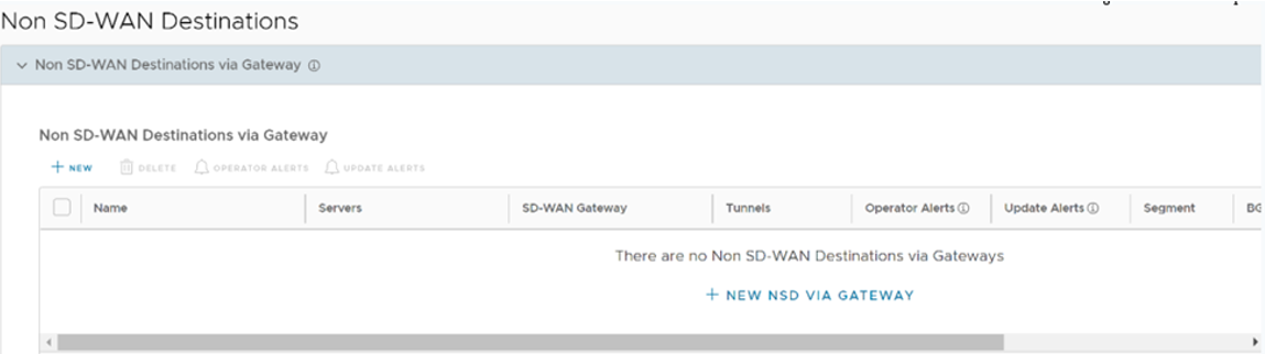
- Click +New to create a new Non SD-WAN Destination.
The Non SD-WAN Destinations via Gateway dialog displays, as show in the image below.
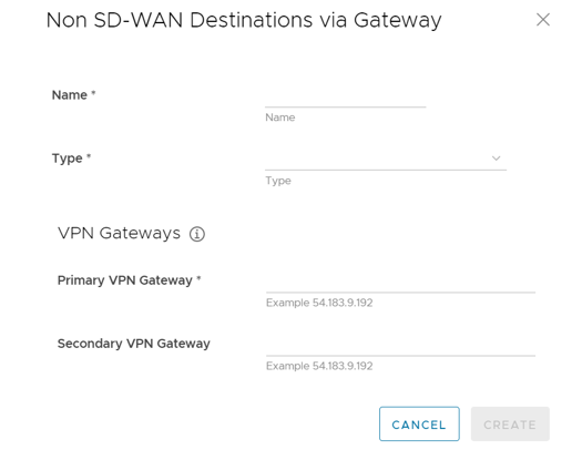
- In the Non SD-WAN Destinations via Gateway area (see image above), configure the following fields as described in the table below.
Option Description Name Enter a name for the Non SD-WAN Destination in the text box. Type Select an IPsec tunnel type from the drop-down menu. Primary VPN Gateway Enter a valid IP address Secondary VPN Gateway Enter a valid IP address. This field is optional The Non SD-WAN Destinations via Gateway is created, as shown in the image below.
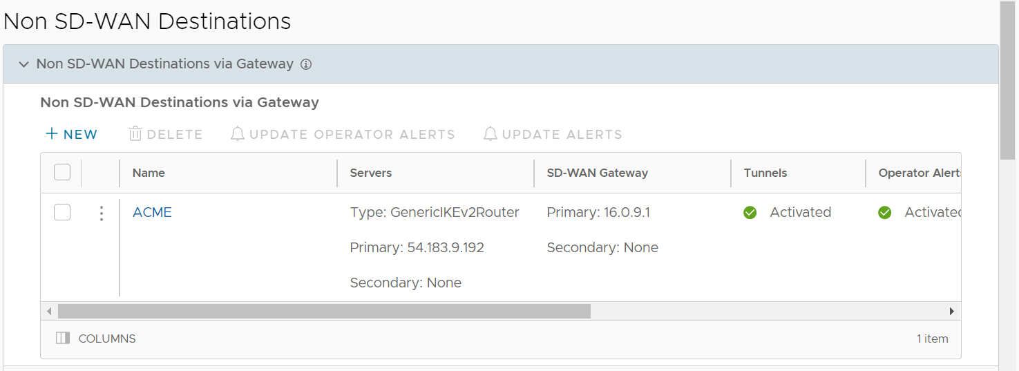
- In the Non SD-WAN Destination via Gateway area, slide the grey bar to the far right to the BGP column.
Click the Edit link under the BGP column.
If the Edit link does not display under the BGP column, see the section titled, "Configure a Tunnel Between a Branch and a Non SD-WAN Destinations via Edge" to enable an Edge to Non SD-WAN via Gateway.
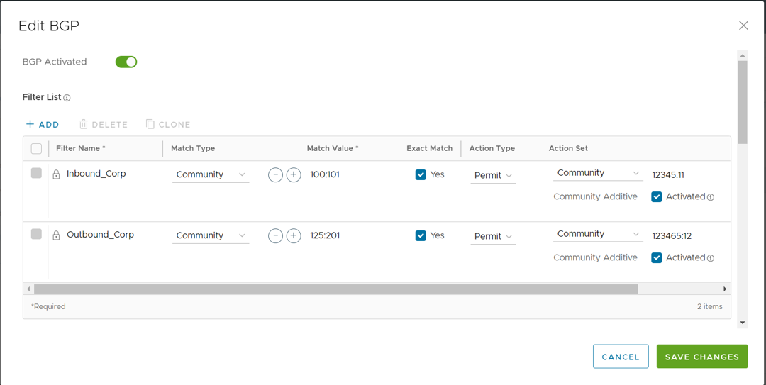
After clicking the Edit link under the BGP column, the Edit BGP dialog displays.
- Toggle the BGP Activated radio button to the right to turn it green.
- Click +Add to create one or more filters. These filters are applied to the neighbor to deny or change the attributes of the route. The same filter can be used for multiple neighbors.
- Configure the options In the Filter List area, as described in the table below.
Option Description Filter Name Enter a descriptive name for the BGP filter. Match Type and Value Choose the type of the routes to be matched with the filter:
- Prefix for IPv4 or IPv6: Choose to match with a prefix for IPv4 or IPv6 address and enter the
corresponding prefix IP address in the Value field.
- Community: Choose to match with a community and enter the community string in the Value field.
Exact Match The filter action is performed only when the BGP routes match exactly with the specified prefix or community string. By default, this option is enabled. Action Type Choose the action to be performed when the BGP routes match with the specified prefix or the community string. You can either permit or deny the traffic. Action Set When the BGP routes match the specified criteria, you can set to route the traffic to a network based on the attributes of the path. Select one of the following options from the drop-down list: - None: The attributes of the matching routes remain the same.
- Local Preference: The matching traffic is routed to the path with the specified local preference.
- Community: The matching routes are filtered by the specified community string. You can also select the Community Additive check box to enable the additive option, which appends the community value to existing communities.
- Metric: The matching traffic is routed to the path with the specified metric value.
- AS-Path-Prepend: Allows pre-pending multiple entries of Autonomous System (AS) to a BGP route.
- Click the plus (+) icon to add more matching rules for the filter. Repeat the procedure to create more filters.
The configured filters are displayed in the Filter List area.
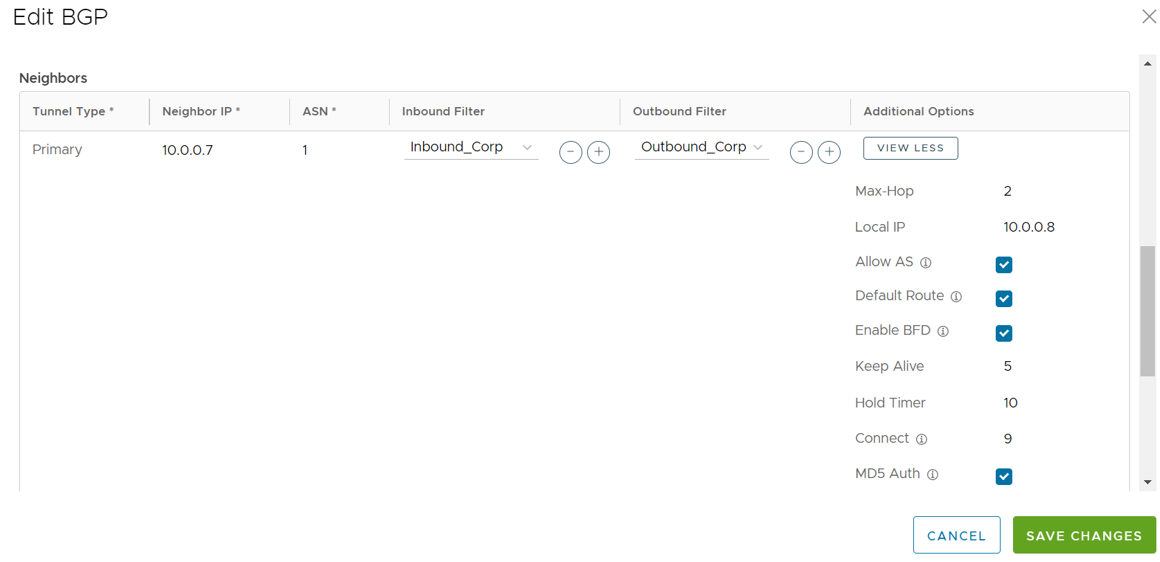
- In the BGP Editor window, configure the BGP settings for the Primary and Secondary Gateways.
Note: The Secondary Gateway option is available only if you have configured a secondary Gateway for the corresponding Non SD-WAN Destination.Note: For a customer deployment where a Non VMware SD-WAN Destination (NSD) via Gateway is configured to use redundant tunnels, if the Primary and Secondary Gateways advertise a prefix with an equal AS path to the Primary and Secondary NSD tunnels, the Primary NSD tunnel will prefer a redundant Gateway path over the Primary Gateway. The impact of the Primary NSD over Gateway tunnel preferring the redundant Gateway path over the Primary Gateway is experienced only for return traffic to the Gateway from the NSD.
If you do not want your BGP router to prefer the redundant Gateway, the workaround is to configure AS-PATH prepend and set the metric filter to a higher (3 or more) metric for the advertised prefix in the redundant Gateway. Doing this ensures the NSD's primary tunnel chooses the Primary Gateway for return traffic.
- In the Primary Cloud Gateway section, enter the local ASN and the Router ID.
- Scroll down to the Neighbors area and click +Add.
- Configure the following settings in the Neighbors area, as described in the table below.
Option Description Local ASN Enter the local Autonomous System Number (ASN) Router ID Enter the BGP Router ID Neighbor IP Enter the IP address of the BGP neighbor ASN Enter the ASN of the neighbor Inbound Filter Select an Inbound filer from the drop-down list Outbound Filter Select an Outbound filer from the drop-down list Additional Options – Click the view all link to configure the following additional settings: Local IP Local IP address is the equivalent of a loopback IP address. Enter an IP address that the BGP neighborships can use as the source IP address for the outgoing packets. Max-hop Enter the number of maximum hops to enable multi-hop for the BGP peers. For the 5.1 release and later, the range is from 2 to 255 and the default value is 2. Note: When upgrading to the 5.1 release, any max-hop value of 1 will automatically be updated to a max-hop value of 2.Note: This field is available only for eBGP neighbors, when the local ASN and the neighboring ASN are different.Allow AS Select the check box to allow the BGP routes to be received and processed even if the Gateway detects its own ASN in the AS-Path. Default Route The Default Route adds a network statement in the BGP configuration to advertise the default route to the neighbor. Enable BFD Enables subscription to the existing BFD session for the BGP neighbor. Keep Alive Enter the keep alive timer in seconds, which is the duration between the keep alive messages that are sent to the peer. The range is from 1 to 65535 seconds. The default value is 60 seconds. Hold Timer Enter the hold timer in seconds. When the keep alive message is not received for the specified time, the peer is considered as down. The range is from 1 to 65535 seconds. The default value is 180 seconds. Connect Enter the time interval to try a new TCP connection with the peer if it detects that the TCP session is not passive. The default value is 120 seconds. MD5 Auth Select the check box to enable BGP MD5 authentication. This option is used in a legacy network or federal network, and is used as a security guard for BGP peering. MD5 Password Enter a password for MD5 authentication. Note: Starting from the 4.5 release, the use of the special character "<" in the password is no longer supported. In cases where users have already used "<" in their passwords in previous releases, they must remove it to save any changes on the page.The configured Neighbors are displayed in the Neighbors area.
Click the Save Changes button to save all changes.
 Note: Over Multi-hop BGP, the system might learn routes that require recursive lookup. These routes have a next-hop IP which is not in a connected subnet, and do not have a valid exit Interface. In this case, the routes must have the next-hop IP resolved using another route in the routing table that has an exit Interface. When there is traffic for a destination that needs these routes to be looked up, routes requiring recursive lookup will get resolved to a connected Next Hop IP address and Interface. Until the recursive resolution happens, the recursive routes point to an intermediate Interface. For more information about Multi-hop BGP Routes, see the "Remote Diagnostic Tests on Edges" section in the VMware SD-WAN Troubleshooting Guide published at https://docs.vmware.com/en/VMware-SD-WAN/index.html.
Route Summarization
The Route Summarization feature is available in the 5.2 release, for an overview and use case of this functionality, see Route Summarization. For configuration details, follow the steps below.
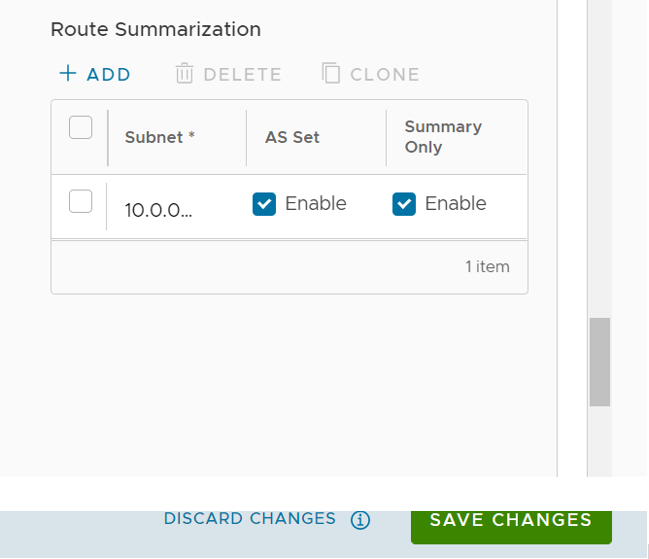
- Scroll down to the Route Summarization area.
- Click +Add in the Route Summarization area. A new row is added to the Route Summarization area.
Configure route summarization, as described in the table below.
Option Description Filter Name Enter a descriptive name for the BGP filter. Subnet Enter the IP subnet. AS Set Generate AS set path information from the summarized routes (while advertising the summary route to the peer). Under the AS Set column, click the Yes check box if applicable. Summary Only Click the Yes check box to allow only the summarized route to be sent. - Add additional routes, if necessary, by clicking +Add. To Clone or Delete a route summarization, use the appropriate buttons, located next to +Add.
The BGP Settings section displays the BGP configuration settings.
- Click Save Changes when complete to save the configuration.
