


VMware SASE supports interconnection of multiple Hub Edges and/or Hub Clusters to increase the range of Spoke Edges that can communicate with each other. This feature allows communication between the Spoke Edges connected to one Hub Edge/Hub Cluster and the Spoke Edges connected to another Hub Edge/Hub Cluster, using multiple overlay and underlay connections.
When a Spoke Edge tries to connect to a Hub Cluster, one of the members from the Hub Cluster is selected as the Hub to the Spoke Edge. If this Hub goes down, another member from the same Hub Cluster is automatically selected to serve the Spoke Edge, without any user configuration. The Hub Cluster members are connected to each other via underlay (BGP), and can exchange the routes and data using this underlay connection. Spoke Edges connected to different members of the same Hub Cluster can then communicate with each other using this underlay connection. This solution provides better resiliency.
- The Hub or Cluster Interconnect feature must be activated.
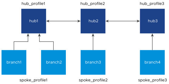
- The Branch to Hub Site (Permanent VPN) check box must be selected. The two interconnected Hub nodes must be configured as Hubs to each other as explained in the below table.
| Profile | Hubs Designation |
|---|---|
| hub_profile1 | hub2 |
| hub_profile2 | hub1 and hub3 |
| hub_profile3 | hub2 |
When Hub or Cluster Interconnect feature is activated, tunnels are formed from one Cluster to another Cluster with at least one peer in other Cluster. Based on the condition, two members from one Cluster can form tunnels to same members in another Cluster. In case of individual Hub and Hub Cluster interconnect, all the Cluster members form tunnels to that individual Hub. The end Spoke Edges connected to these Hub Clusters can then communicate with each other through these two Hub Clusters and the intermediate VMware SD-WAN Routing Protocol hops.
The intra Cluster routes are advertised with special BGP extended community, wherein the last four bytes of the Cluster ID are embedded in the extended community. For example, if the Cluster ID is fee2f589-eab6-4738-88f2-8af84b1a3d9c, 4b1a3d9c is reversed and used to derive the Cluster community as 9c3d1a4b00000003. Based on this community tag, the intra Cluster routes are filtered out towards the controller. This avoids reflecting redundant routes from multiple Cluster members.
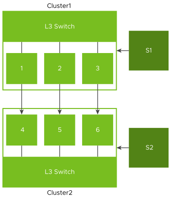
- Overlay connection between S1 and C1.
- Overlay connection between S2 and C2.
- Overlay connection between C1 and C2.
- Underlay connection within C1.
- Underlay connection within C2.
In this way, the Hub Clusters can exchange routes with each other, providing a way for the packets to flow between Spoke Edges connected to different Hub Clusters.
- Dynamic branch to branch is supported between Spokes connected to two different or same Clusters.
- Profile isolation in Spoke Profile is supported.
- Internet Backhaul via Cluster is supported.
Limitations:
- Hub or Cluster Interconnect through Gateway is not supported.
- Exchanging routes between Hub Cluster members using OSPF is not supported.
- Asymmetric routing can occur when two Clusters are interconnected. Enhanced Firewall Services or Stateful Firewall must not be activated as they can block the traffic due to asymmetric routing.
- When all the Overlay tunnels go down between two Cluster members, traffic drop is expected until they form a tunnel with other members in the peer Cluster.
- If there are more than one LAN/WAN routers running BGP with Cluster, Trusted Source check box must be selected and the value of Reverse Path Forwarding must be Not enabled, on the Cluster Edge interfaces connecting BGP routers. For more information, see Configure Interface Settings for Edges.
- Without Hub or Cluster Interconnect feature, a Cluster Hub Profile cannot have another Cluster or Hub configured as a Hub.
Configuring Hub or Cluster Interconnect
Prerequisites
- Ensure to upgrade the Orchestrator, Gateways, and Hubs or Hub Clusters to version 5.4.0.0 or above.
- The Cloud VPN service must be activated for the Cluster Profile associated with the Edge Clusters or Hubs.
- The Branch to Branch VPN (Transit & Dynamic) check box must not be selected in interconnect Hub Profiles, as shown below.
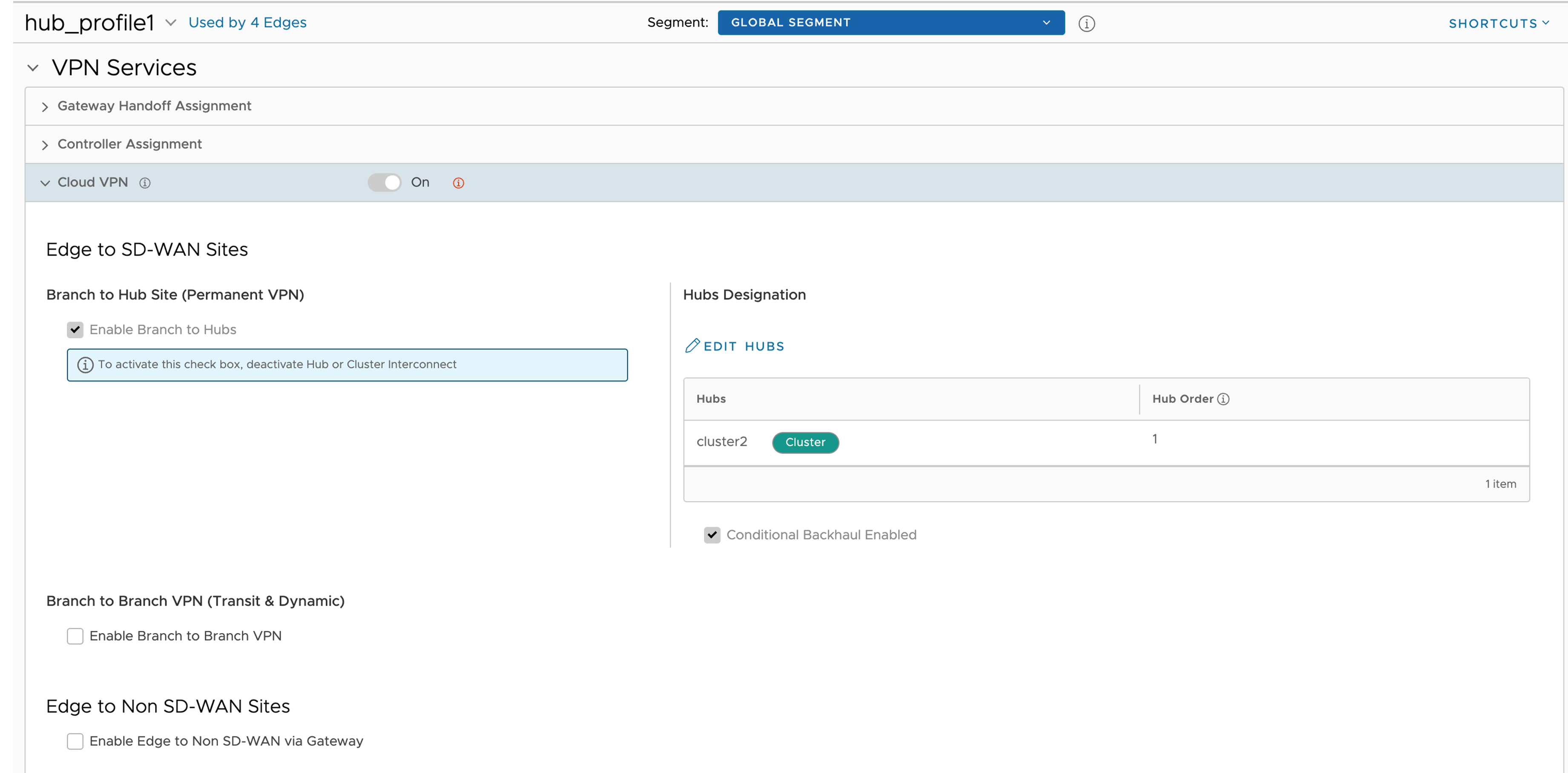
Configuring Hubs Designation on interconnect Profiles is sufficient for end to end communication with all nodes. You can configure the Branch to Branch via Hubs for Spoke Profiles.
- Hub or Cluster Interconnect feature must be activated in all the Hub Profiles involved in the interconnect process.
- Cluster members must run the BGP with LAN/L3 router, and the router must be configured to forward the BGP extended communities.
- There must be at least one common Gateway for all Edges (Spokes and Hubs) in case of Partner Gateway assignment. The order of Partner Gateways assignment should be same across all the Hub/Cluster Profiles.
Procedure
- Designate Hub to the Cluster Profile:
- On the Profile Device Settings screen, go to VPN Services and turn on the Cloud VPN service.
- Select the Enable Branch to Hubs check box.
- Click Edit Hubs located under Hub Designation.
- Click Update Hubs.
- On the Profile Device Settings screen, go to VPN Services and turn on the Cloud VPN service.
- Activate 'Hub or Cluster Interconnect' feature: On the Profile Device Settings screen, navigate to Hub or Cluster Interconnect located under VPN Services, and then select the Enable check box.
 Note: Hub and Cluster Interconnect configurations can be done only at Profile level.This activates the feature and creates a tunnel between the Hub Clusters which allows their respective Spoke Edges to communicate with each other.Caution: Activating or deactivating the Hub or Cluster Interconnect feature causes all Edge devices associated with the Profile to restart. Hence, it is recommended to configure the feature only in a maintenance mode to prevent traffic disruption.
What to do next
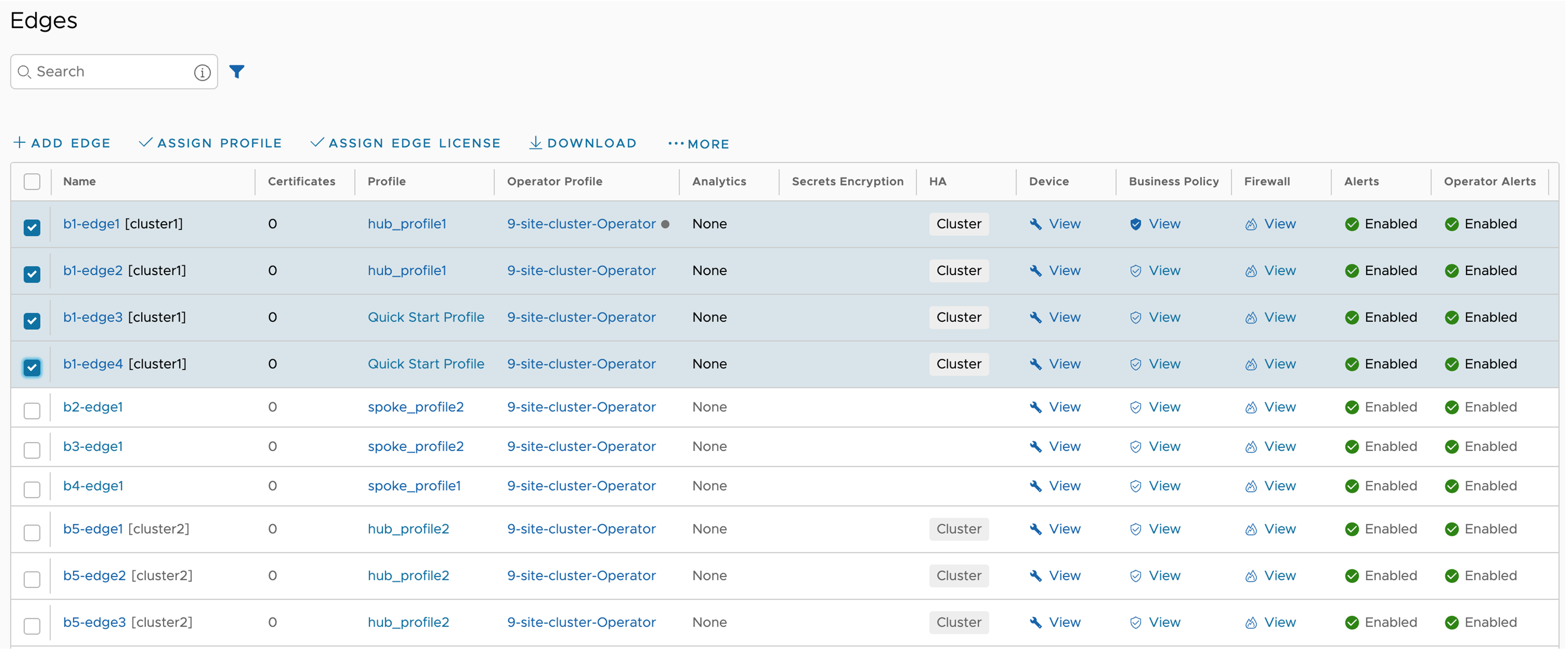
- Assign Profiles to the Edges: Navigate to to assign Profiles to the available Edges.
- You can monitor the events by navigating to . The following table lists the new Orchestrator events added for the Hub or Cluster Interconnect feature:
Event Level Description CLUSTER_IC_ENABLED Info This event is generated whenever an Edge is associated with a Cluster service. CLUSTER_IC_DISABLED Info This event is generated whenever an Edge is disassociated from a Cluster service. CLUSTER_IC_PEER_UP Warning This event is generated whenever the first interconnect tunnel between two Cluster Hub nodes, comes up. CLUSTER_IC_PEER_DOWN Warning This event is generated whenever the last interconnect tunnel between two Cluster Hub nodes, goes down. CLUSTER_IC_TUNNEL_UP Warning This event is generated whenever interconnect tunnels between the Clusters, come up. CLUSTER_IC_TUNNEL_DOWN Warning This event is generated whenever the interconnect tunnels between the Clusters, go down. HUB_CLUSTER_REBALANCE Warning This event is generated whenever a Cluster rebalance action is triggered.
- After Hub or Cluster Interconnect feature is activated, removing or adding a Cluster member under Network Services, triggers service restart on that particular Edge. It is advised to perform such actions during maintenance window.
- When a Spoke is connected to primary and secondary Hub Cluster and learns same route from both of them, the route order is based on BGP attributes. If the routing attributes are same, then route sorting happens based on VPN Hub order configuration. On the other hand, the Spoke's subnets are redistributed by primary and secondary Hub or Hub Cluster to their neighbor with metric (MED) 33 and 34 respectively. You must configure "bgp always-compare-med" in the neighbor router for symmetric routing.
- When Hub or Hub Clusters are connected to MPLS core through CE, you must configure UPLINK tag in those BGP neighbors.
- In a network set up with a spoke, a primary hub, and a secondary hub, initiating a flow from behind the spoke creates a local flow on the spoke that is then routed through the primary hub. If the primary hub goes down, the route of the local flow is updated to the secondary hub. Since the route is checked with each packet for local flows, when the primary hub comes back up, the route is updated accordingly. However, the behavior is different when the flow is a peer flow. In this case, if the primary hub goes down, the peer flow is routed through the secondary hub, but when the primary hub comes back up, the peer route is not updated. This is because the peer flow relies on the peer's updates, which is the expected behavior. The workaround for this is to flush the affected flows.
