


During the L2VPN discovery process, the MPLS Topology Servercreates within its repository a data model representation of the discovered L2VPN topology. The LDP-signaled L2VPN data model is shown in LDP-signaled L2VPN data model, and the BGP-signaled L2VPN data model is shown in BGP-signaled L2VPN data model.
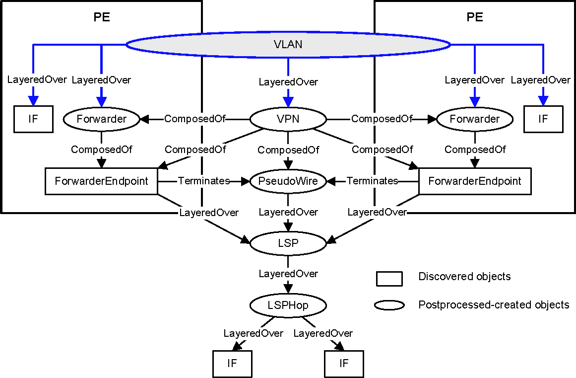
The VLAN modeling for Ethernet-VLAN VPWS and VPLS is shown in VLAN modeling in the L2VPN data model.
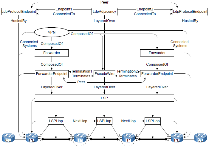
LDP-signaled L2VPN data model
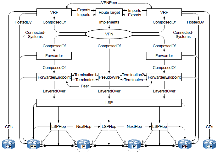
BGP-signaled L2VPN data model
Typically, every relationship has an inverse relationship. For example, the relationship “Underlying” is the inverse relationship of “LayeredOver.”
GUID-5F977C09-E16B-4A9A-BAF1-10C298479894.html#GUID-5F977C09-E16B-4A9A-BAF1-10C298479894___MPLS_DISCO_PROCESS_38631and GUID-5F977C09-E16B-4A9A-BAF1-10C298479894.html#GUID-5F977C09-E16B-4A9A-BAF1-10C298479894___MPLS_DISCO_PROCESS_93469present descriptions of the LdpProtocolEndpoint, LdpAdjacency, Forwarder, ForwarderEndpoint, PseudoWire, VRF, RouteTarget, VPN, and VLAN classes. More detailed descriptions of these classes are available in the VMware Smart Assurance MPLS Management Suite User Guide.
The discovery and modeling of the LdpProtocolEndpoint and LdpAdjacency objects is specific to LDP-signaled L2VPNs. The discovery and modeling of the VRF and RouteTarget objects is specific to BGP-signaled L2VPNs.
